EP0573291A2 - Cartridge used for a disc-shaped recording medium - Google Patents
Cartridge used for a disc-shaped recording medium Download PDFInfo
- Publication number
- EP0573291A2 EP0573291A2 EP93304310A EP93304310A EP0573291A2 EP 0573291 A2 EP0573291 A2 EP 0573291A2 EP 93304310 A EP93304310 A EP 93304310A EP 93304310 A EP93304310 A EP 93304310A EP 0573291 A2 EP0573291 A2 EP 0573291A2
- Authority
- EP
- European Patent Office
- Prior art keywords
- recording medium
- disc
- clamping plate
- shaped recording
- recessed section
- Prior art date
- Legal status (The legal status is an assumption and is not a legal conclusion. Google has not performed a legal analysis and makes no representation as to the accuracy of the status listed.)
- Granted
Links
- 230000003287 optical effect Effects 0.000 claims abstract description 62
- 230000002093 peripheral effect Effects 0.000 claims abstract description 4
- 238000013500 data storage Methods 0.000 claims 3
- 238000000034 method Methods 0.000 abstract description 10
- 238000004519 manufacturing process Methods 0.000 abstract description 8
- 230000008569 process Effects 0.000 abstract description 4
- 239000000463 material Substances 0.000 description 5
- 239000000853 adhesive Substances 0.000 description 4
- 230000001070 adhesive effect Effects 0.000 description 4
- 239000002390 adhesive tape Substances 0.000 description 2
- 230000008901 benefit Effects 0.000 description 2
- 238000007796 conventional method Methods 0.000 description 2
- 239000000428 dust Substances 0.000 description 2
- 239000004033 plastic Substances 0.000 description 2
- 239000000126 substance Substances 0.000 description 2
- GNLJOAHHAPACCT-UHFFFAOYSA-N 4-diethoxyphosphorylmorpholine Chemical compound CCOP(=O)(OCC)N1CCOCC1 GNLJOAHHAPACCT-UHFFFAOYSA-N 0.000 description 1
- 238000002347 injection Methods 0.000 description 1
- 239000007924 injection Substances 0.000 description 1
- 230000007246 mechanism Effects 0.000 description 1
- 238000012986 modification Methods 0.000 description 1
- 230000004048 modification Effects 0.000 description 1
- 239000004417 polycarbonate Substances 0.000 description 1
- 229920000515 polycarbonate Polymers 0.000 description 1
- 230000009467 reduction Effects 0.000 description 1
- 239000011347 resin Substances 0.000 description 1
- 229920005989 resin Polymers 0.000 description 1
- 239000000758 substrate Substances 0.000 description 1
Images

Classifications
-
- G—PHYSICS
- G11—INFORMATION STORAGE
- G11B—INFORMATION STORAGE BASED ON RELATIVE MOVEMENT BETWEEN RECORD CARRIER AND TRANSDUCER
- G11B23/00—Record carriers not specific to the method of recording or reproducing; Accessories, e.g. containers, specially adapted for co-operation with the recording or reproducing apparatus ; Intermediate mediums; Apparatus or processes specially adapted for their manufacture
- G11B23/0014—Record carriers not specific to the method of recording or reproducing; Accessories, e.g. containers, specially adapted for co-operation with the recording or reproducing apparatus ; Intermediate mediums; Apparatus or processes specially adapted for their manufacture record carriers not specifically of filamentary or web form
- G11B23/0021—Record carriers not specific to the method of recording or reproducing; Accessories, e.g. containers, specially adapted for co-operation with the recording or reproducing apparatus ; Intermediate mediums; Apparatus or processes specially adapted for their manufacture record carriers not specifically of filamentary or web form discs
- G11B23/0028—Details
- G11B23/0035—Details means incorporated in the disc, e.g. hub, to enable its guiding, loading or driving
-
- G—PHYSICS
- G11—INFORMATION STORAGE
- G11B—INFORMATION STORAGE BASED ON RELATIVE MOVEMENT BETWEEN RECORD CARRIER AND TRANSDUCER
- G11B23/00—Record carriers not specific to the method of recording or reproducing; Accessories, e.g. containers, specially adapted for co-operation with the recording or reproducing apparatus ; Intermediate mediums; Apparatus or processes specially adapted for their manufacture
- G11B23/02—Containers; Storing means both adapted to cooperate with the recording or reproducing means
- G11B23/03—Containers for flat record carriers
- G11B23/0301—Details
- G11B23/0307—Positioning or centering features
Definitions
- the present invention relates to a cartridge used for a disc-shaped recording medium, which houses a disc-shaped recording medium such as an optical disk.
- CDs compact disks
- WO disks write-once type
- MO disks magneto-optical disks of rewritable type
- the WO disk or MO disk is drawn and clamped onto the turntable by a magnetic force, which is exerted to a hub attached to the disk, and rotated thereon.
- WO disks and MO disks In comparison with CDs, WO disks and MO disks have the advantage that they are protected against scratches and dust since they are kept in the cartridge. Further, WO disks and MO disks have better operability when placed onto and removed from the driver since they are inserted therein together with the cartridge.
- the hub attached to the disk has two functions: one for minimizing the eccentricity that occurs between guide grooves formed on the WO disk or MO disk and the rotation center of the turntable; and the other for permitting the WO disk or MO disk to be drawn into position by the magnet installed on the turntable.
- the guide grooves are provided for allowing the quick-random-access of information on the information area of the WO disk or MO disk. They are formed on the information area in a spiral shape with their center virtually concentric with the rotational axis of the WO disk or the MO disk.
- optical disks of another type that is, MDs
- DCC-MD guide book written by Kinya Murata, Dempa Publications Inc.
- MD refers to Mini Disk.
- the MD is provided with a cartridge for housing an optical disk so as to protect it from scratches and dust.
- an optical disk 11 which functions as a recording medium of the magneto-optical method, is housed in a cartridge 12.
- a hub 13 for clamping the optical disk 11 onto a turntable, not shown, is installed.
- each raised portion 14 is designed to contact the non-information area of the optical disk 11. Thus, each raised portion 14 protects the information area of the magneto-optical disk 11 from contacting the cartridge case 12, thereby preventing the information area from being damaged.
- the hub 13 which is formed to have a plate-shape, is made of a magnetic substance so as to be attracted by the magnet.
- the only function imparted to the hub 13 is to clamp the optical disk 11 onto the turntable, not shown, by using the magnetic force; therefore, it is not necessary to provide a precise positioning operation such as needed in the WO disk and the MO disk.
- the cartridge used for the disc-shaped recording medium of the present invention is provided with: a rotationally-driven recording medium which is of a disc-shape with a recessed section; a clamping plate, which is placed at the recessed section, for clamping the disc-shaped recording medium by the use of a magnetic force; and a case for housing the disc-shaped recording medium and the clamping plate so as to permit them to freely rotate.
- the clamping plate has a height dimension (in the rotational-axis direction of the recording medium) that is set to be greater than the distance between the recording medium and the inner surface of the case.
- the clamping plate tends to move inside the recessed section and come into contact with the case.
- the above arrangement allows the clamping plate to remain in the recessed section because the height dimension in the rotational-axis direction of the clamping plate is greater than the distance between the recording medium and the inner surface of the case.
- the assembly of the cartridge is simplified: the clamping plate need not be fixed to the recording medium; and after inserting the clamping plate into the recessed section formed in the recording medium, the cartridge is assembled by putting the recording medium into the case.
- the cartridge is assembled by putting the recording medium into the case.
- the clamping plate is formed into a hat shape having a brim portion, and the brim portion is inserted into and brought into contact with the recessed section.
- a restricting protrusion is formed on the inner surface of the case in a manner as to protrude toward the clamping plate.
- the distance between the restricting protrusion and the clamping plate is set to be smaller than the depth dimension of the recessed section.
- a stopping member is formed on the inner surface of the case that faces the clamping plate, in the rotational-axis direction of the recording medium, and an engagement hole may be provided in the clamping plate so that the stopping member comes to fit it when the clamping plate moves inside the recessed section.
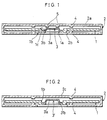
- Fig. 1 is a cross-sectional view of a cartridge used for a disc-shaped recording medium that indicates one embodiment of the present invention.
- Fig. 2 is a cross-sectional view of a cartridge used for a disc-shaped recording medium that indicates another embodiment of the present invention.
- Fig. 3 is a cross-sectional view of a cartridge used for a disc-shaped recording medium that indicates a further embodiment of the present invention.
- Fig. 4 is a cross-sectional view of a conventional optical disk cartridge.
- Embodiment 1 a cartridge used for a disc-shaped recording medium is provided with a cartridge case 2 for housing an optical disk 1 as a disc-shaped recording medium.
- a recording medium such as a mini-disk is exemplified as the optical disk 1.
- the optical disk 1 which is formed into a disk-shape using a resin, such as polycarbonate having superior dimensional stability, as a substrate, is provided with a circular center hole 1a that is coaxial with the rotational-axis of the optical disk 1.
- the circular center hole 1a fits the raised section of a turntable, not shown, so that the optical disk 1 is driven to rotate.
- the optical disk 1 has an information area on one side thereof, on and from which information is recorded and reproduced.
- the information area includes a lead-in area, a U-TOC (User's Table Of Contents) area, a program area and a lead-out area in this order from its inner side.
- U-TOC User's Table Of Contents
- the lead-in area which is exclusively used for reproduction, is provided with land sections and pit sections on its surface, and information is reproduced by the use of those land sections and pit sections.
- the U-TOC area, the program area and the lead-out area are respectively provided with guiding grooves (pre-grooves), and recording and reproduction are thus available thereon and therefrom through the magneto-optical recording method.
- the guiding grooves which are formed for providing quick random-access, have a spiral shape extending from inside toward outside that is virtually coaxial with the rotational-axis of the optical disk 1.
- the cartridge case 2 which is shaped into a rectangular parallelopiped box made of plastic, is provided with a space 2a for housing the optical disk 1 so as to allow it to freely rotate therein and a through hole 2b through which the turntable (not shown) penetrates so as to rotate freely.
- the hub 3 is made of a magnetic substance that is attracted by a magnet, and is formed into a hat shape.
- the hat-shaped hub 3 has a flattened cone-shape portion: the smaller-diameter side of which is closed, while the greater-diameter side is open.
- the hub 3 also has a brim portion 3b having a flange-shape extending from the edge of the opening on the greater-diameter side outward in the direction of the diameter.
- a pair of protrusions 4 are respectively installed so that they are aligned face to face with each other, in order to prevent the information area of the optical disk 1 from being damaged due to its contact against the inner face of the cartridge case 2. Additionally, in the present specification, the rotational-axis direction of the optical disk 1 stands for the vertical direction.
- the distance between the tips of the protrusions 4 is set to be greater than the thickness of the information area of the optical disk 1.
- the protrusions 4 are not necessarily limited in their shape as long as they can support the disk 1 while contacting the non-information area of the disk 1; for example, they are formed into a ring shape that is virtually coaxial with the through hole 2b.
- the optical disk 1 is provided with a recessed section 1b to which the hub 3 is fit.
- the recessed section 1b is formed along the peripheral edge of the center hole 1a recessing toward the through hole 2b of the cartridge case 2.
- the recessed section 1b is coaxial with the central axis of the center hole 1a, and has a circular shape in its lateral cross-section perpendicular to the central axis.
- the depth of the recessed section 1b is set to be greater as compared with conventional arrangements.
- the depth represents the length in the rotational-axis direction.
- the hub 3 having the hat shape is set to be greater in its height than that of conventional arrangements.
- a restricting protrusion 5 is installed so that it restricts the movement of the hub 3.
- the restricting protrusion 5 is installed in a manner as to protrude from the inner surface of the cartridge case 2 toward the top portion of the hub 3.
- the restricting protrusion 5 restricts the movement of the hub 3 when the hub 3 moves upward and the top portion of the hub 3 comes into contact with the tip of the restricting protrusion 5; thus, the brim portion 3b is designed to always stay inside the recessed section 1b.
- the distance between the tip of the restricting protrusion 5 and the top portion of the hub 3 is set to be smaller than the depth of the recessed section 1b.
- the restricting protrusion 5 is designed in such a manner that when the optical disk 1 is moved in the rotational-axis direction and driven, the top portion of the hub 3, which is moved together with the optical disk 1, is kept apart from the restricting protrusion 5. Thus, the optical disk 1 is rotated without contacting the restricting protrusion 5.
- the restricting protrusion 5 is not necessarily limited in its shape and number. If installed as one unit, it may have a ring-shape that is coaxial with the rotational-axis of the optical disk 1, or it may have a virtual pillar-shape. If installed as plural units, they may respectively have a pillar-shape or a pipe-shape.
- restricting protrusion 5 are preferably designed so as to be symmetrical with respect to the rotational axis. This is to restrict the hub 3 from tilting against the rotational axis and to prevent the hub 3 from coming off from the recessed section 1b when the restricting protrusions 5 come into contact with the hub 3.
- the restricting protrusion 5 is formed simultaneously as the cartridge case 2 is made; therefore, the production of the restricting protrusion 5 is comparatively simple.
- the cartridge case 2 when the cartridge case 2 is inserted into, for example, a driver, the cartridge case 2 moves with respect to a turntable, not shown, in the rotational direction of the turntable, and the raised portion of the turntable is fitted to the center hole 1a. Since the raised portion has a flattened cone shape that is coaxial with the turntable, positioning is made so that the optical disk 1 is set to be coaxial with the turntable.
- the turntable comes into contact with the clamping area 1c of the optical disk 1, and raises the optical disk 1 with respect to the cartridge case 2.
- the optical disk 1 is thus separated from the protrusions 4.
- the magnet which is attached to the top of the raised portion of the turntable, attracts the hub 3 toward the turntable, and the brim portion 3b of the hub 3 thus presses the optical disk 1 against the turntable, thereby clamping it onto the turntable.
- the optical disk 1 is driven to rotate by the turntable without contacting any portion of the cartridge case 2. Further, the restricting protrusion 5, installed on the inner face of the cartridge case 2, is kept apart from the top portion of the hub 3, and does not interrupt the rotation of the optical disk 1.
- the restricting protrusion 5 restricts the range of movement of the hub 3 in the rotational-axis direction; therefore, it is possible to prevent the hub 3 from coming off from the recessed section 1b, even if the cartridge case 2 is vertically placed, or is placed upside down.
- the hub 3 when the cartridge case 2 is inserted into, for example, a driver, the hub 3 is always maintained inside the recessed section 1b while being kept coaxial with the rotational axis of the optical disk 1; this ensures a secure clamp of the optical disk 1 by the hub 3.
- the hub 3 need not be fixed to the optical disk 1; and after inserting the hub 3 into the recessed section 1b formed around the center hole 1a of the optical disk 1 while keeping it coaxial with the rotational axis, the cartridge case 2 is assembled by putting the optical disk 1 into the case.
- embodiment 1 Since the arrangement of embodiment 1 makes it possible to eliminate bonding members and a particular device for use in fixing, which are needed in the conventional methods, the manufacturing cost can be reduced.
- a cartridge used for a disc-shaped recording medium although it has virtually the same shape as that described in embodiment 1, is not provided with a restricting protrusion 5 to be installed on the cartridge case 2, and instead of the hub 3 shown in Fig. 1, it is provided with a hub 3' shown in Fig. 2.
- the hub 3' is formed into a hat shape as in embodiment 1, and the height of the flattened cone-shape portion 3'a thereof is set to be even greater than that of the hub 3 shown in Fig. 1. That is, it is set to be greater than the distance between the optical disk 1 and the inner face of the upper shell 2c of the cartridge case 2. In other words, the depth of the recessed section 1b is set to be greater than the distance between the top portion of the flattened cone-shape portion 3'a and the inner face of the upper shell 2c.
- the hub 3' is always maintained inside the recessed section 1b when the cartridge case 2 is inserted into, for example, a driver.
- a cartridge used for a disc-shaped recording medium although it has virtually the same shape as that described in embodiment 1, is provided with a hub 3'' shown in Fig. 3 instead of the hub 3 shown in Fig. 1, and instead of the restricting protrusion 5 of Fig. 1, it is provided with a projecting pin 6. Further, the hub 3'' is provided with a central opening 3''c that is formed in the center of the top portion of the flattened-cone-shaped 3''a thereof.
- the projecting pin 6 is formed on the inner face of the cartridge case 2 in a manner as to protrude toward the central opening 3''c in the rotational-axis direction of the optical disk 1. As the hub 3'' moves in the rotational-axis direction of the optical disk 1, the projecting pin 6 is freely fit to and inserted into the central opening 3''c.
- the shape of the projecting pin 6 is not necessarily limited: for example, it may have a column shape or a square pillar.
- the hub 3'' is always maintained inside the recessed section 1b when the cartridge case 2 is inserted into, for example, a driver.
Landscapes
- Holding Or Fastening Of Disk On Rotational Shaft (AREA)
Abstract
Description
- The present invention relates to a cartridge used for a disc-shaped recording medium, which houses a disc-shaped recording medium such as an optical disk.
- As to methods for driving and rotating an optical disk by the use of a driver (player), it is known in the art that regarding compact disks (hereinafter, referred to as CDs), a CD is taken out of a case, and after placing it on the turntable of a driver, the CD is mechanically clamped to the turntable by the disk holder, and rotated.
- In contrast, regarding optical disks of write-once type (hereinafter, referred to as WO disks) and magneto-optical disks of rewritable type (hereinafter, referred to as MO disks), the disk is inserted into a driver together with its cartridge, and rotated.
- More specifically, in the driver, the WO disk or MO disk is drawn and clamped onto the turntable by a magnetic force, which is exerted to a hub attached to the disk, and rotated thereon.
- In comparison with CDs, WO disks and MO disks have the advantage that they are protected against scratches and dust since they are kept in the cartridge. Further, WO disks and MO disks have better operability when placed onto and removed from the driver since they are inserted therein together with the cartridge.
- Here, the hub attached to the disk has two functions: one for minimizing the eccentricity that occurs between guide grooves formed on the WO disk or MO disk and the rotation center of the turntable; and the other for permitting the WO disk or MO disk to be drawn into position by the magnet installed on the turntable. The guide grooves are provided for allowing the quick-random-access of information on the information area of the WO disk or MO disk. They are formed on the information area in a spiral shape with their center virtually concentric with the rotational axis of the WO disk or the MO disk.
- Meanwhile, optical disks of another type, that is, MDs, are shown in a DCC-MD guide book (written by Kinya Murata, Dempa Publications Inc.). Here, DCC refers to Digital Compact Cassette, and MD refers to Mini Disk. As with the WO and MO, the MD is provided with a cartridge for housing an optical disk so as to protect it from scratches and dust.
- As illustrated in Fig. 4, in the MD, an
optical disk 11, which functions as a recording medium of the magneto-optical method, is housed in acartridge 12. In thecartridge 12, ahub 13 for clamping theoptical disk 11 onto a turntable, not shown, is installed. - Further, a pair of ring-shaped raised
portions 14 are formed facing each other inside thecartridge 12. Each raisedportion 14 is designed to contact the non-information area of theoptical disk 11. Thus, each raisedportion 14 protects the information area of the magneto-optical disk 11 from contacting thecartridge case 12, thereby preventing the information area from being damaged. - The
hub 13, which is formed to have a plate-shape, is made of a magnetic substance so as to be attracted by the magnet. The only function imparted to thehub 13 is to clamp theoptical disk 11 onto the turntable, not shown, by using the magnetic force; therefore, it is not necessary to provide a precise positioning operation such as needed in the WO disk and the MO disk. - Accordingly, as to the positioning operation between the guide grooves and the rotation center of the turntable, it is provided by fitting a
center hole 11a to a flattened-cone-shaped projecting portion that is formed on the turntable, which is the same operation as in the CD. - In this arrangement, if the
cartridge 12 is vertically placed, or if it is placed upside down, in the case where thehub 13 is not joined to theoptical disk 11, thehub 13 tends to come out from thecenter hole 11a. When this happens, theoptical disk 11 might not remain clamped onto the turntable, or thehub 13 might hit against thecartridge 12 upon rotation of theoptical disk 11. This results in a drawback wherein the rotation of theoptical disk 11 becomes unstable. - In order to eliminate the drawback, there has been suggested an arrangement wherein the
hub 13 is fixed along the periphery of thecenter hole 11a so as to cover thecenter hole 11a of theoptical disk 11. In order to fix thehub 13 along the periphery of thecenter hole 11a, such methods as using an adhesive or a double-sided adhesive tape have been adopted. Using such methods makes it possible to reduce the manufacturing cost in comparison with the case of the above-mentioned WO disk or MO disk, since no precise positioning mechanism is required. But even such methods result in increased cost since a special fixing device and bonding materials such as adhesives or double-sided adhesive tapes are required. - It is an object of the present invention to provide a cartridge used for a disc-shaped recording medium wherein the clamping function of the hub on the disc-shaped recording medium is maintained without fixing the hub to the disc-shaped recording medium; also, cost reduction is achieved by eliminating the fixing device and the bonding materials previously utilized to fix the hub to the disc-shaped recording medium.
- In order to achieve the above objective, the cartridge used for the disc-shaped recording medium of the present invention is provided with: a rotationally-driven recording medium which is of a disc-shape with a recessed section; a clamping plate, which is placed at the recessed section, for clamping the disc-shaped recording medium by the use of a magnetic force; and a case for housing the disc-shaped recording medium and the clamping plate so as to permit them to freely rotate. The clamping plate has a height dimension (in the rotational-axis direction of the recording medium) that is set to be greater than the distance between the recording medium and the inner surface of the case.
- If the case is vertically placed, or if it is placed upside down, the clamping plate tends to move inside the recessed section and come into contact with the case. However, even in such a situation, the above arrangement allows the clamping plate to remain in the recessed section because the height dimension in the rotational-axis direction of the clamping plate is greater than the distance between the recording medium and the inner surface of the case.
- Therefore, even if the case is placed incorrectly (for example, in a position different from the normal-use horizontal position), that is, in a tilted position or upside down, it is possible to prevent the drawback wherein the clamping plate might come out from the recessed section and intrude between the case and the recording medium.
- Further, when the case is returned to the normal-use position, the clamping plate is maintained at a predetermined position inside the recessed section. Thus, upon inserting the case into the driver, this arrangement ensures a secure clamping of the recording medium onto the turntable of the driver.
- In accordance with the above arrangement, the assembly of the cartridge is simplified: the clamping plate need not be fixed to the recording medium; and after inserting the clamping plate into the recessed section formed in the recording medium, the cartridge is assembled by putting the recording medium into the case. With this arrangement, it is possible to eliminate a special device for joining the clamping plate to the recording medium and the bonding materials such as adhesives that are needed in the conventional methods. Manufacturing cost can, thus, be reduced.
- Moreover, another arrangement may be adopted: the clamping plate is formed into a hat shape having a brim portion, and the brim portion is inserted into and brought into contact with the recessed section. A restricting protrusion is formed on the inner surface of the case in a manner as to protrude toward the clamping plate. Here, the distance between the restricting protrusion and the clamping plate is set to be smaller than the depth dimension of the recessed section.
- Still another arrangement may be adopted: a stopping member is formed on the inner surface of the case that faces the clamping plate, in the rotational-axis direction of the recording medium, and an engagement hole may be provided in the clamping plate so that the stopping member comes to fit it when the clamping plate moves inside the recessed section.
- For a fuller understanding of the nature and advantages of the invention, reference should be made to the ensuing detailed description taken in conjunction with the accompanying drawings.
- Fig. 1 is a cross-sectional view of a cartridge used for a disc-shaped recording medium that indicates one embodiment of the present invention.
- Fig. 2 is a cross-sectional view of a cartridge used for a disc-shaped recording medium that indicates another embodiment of the present invention.
- Fig. 3 is a cross-sectional view of a cartridge used for a disc-shaped recording medium that indicates a further embodiment of the present invention.
- Fig. 4 is a cross-sectional view of a conventional optical disk cartridge.
- The following description will discuss one embodiment of the present invention as
Embodiment 1. As illustrated in Fig. 1, a cartridge used for a disc-shaped recording medium is provided with acartridge case 2 for housing anoptical disk 1 as a disc-shaped recording medium. Here, a recording medium such as a mini-disk is exemplified as theoptical disk 1. - The
optical disk 1, which is formed into a disk-shape using a resin, such as polycarbonate having superior dimensional stability, as a substrate, is provided with acircular center hole 1a that is coaxial with the rotational-axis of theoptical disk 1. Thecircular center hole 1a fits the raised section of a turntable, not shown, so that theoptical disk 1 is driven to rotate. - Further, the
optical disk 1 has an information area on one side thereof, on and from which information is recorded and reproduced. The information area includes a lead-in area, a U-TOC (User's Table Of Contents) area, a program area and a lead-out area in this order from its inner side. - The lead-in area, which is exclusively used for reproduction, is provided with land sections and pit sections on its surface, and information is reproduced by the use of those land sections and pit sections. The U-TOC area, the program area and the lead-out area are respectively provided with guiding grooves (pre-grooves), and recording and reproduction are thus available thereon and therefrom through the magneto-optical recording method.
- The guiding grooves, which are formed for providing quick random-access, have a spiral shape extending from inside toward outside that is virtually coaxial with the rotational-axis of the
optical disk 1. - The
cartridge case 2, which is shaped into a rectangular parallelopiped box made of plastic, is provided with aspace 2a for housing theoptical disk 1 so as to allow it to freely rotate therein and a throughhole 2b through which the turntable (not shown) penetrates so as to rotate freely. - Inside the
cartridge case 2, is installed ahub 3 for clamping theoptical disk 1 onto the turntable (not shown) by the use of a magnetic force. Thehub 3 is made of a magnetic substance that is attracted by a magnet, and is formed into a hat shape. - The hat-shaped
hub 3 has a flattened cone-shape portion: the smaller-diameter side of which is closed, while the greater-diameter side is open. Thehub 3 also has abrim portion 3b having a flange-shape extending from the edge of the opening on the greater-diameter side outward in the direction of the diameter. - On the upper and lower inner faces of the
cartridge case 2, a pair ofprotrusions 4 are respectively installed so that they are aligned face to face with each other, in order to prevent the information area of theoptical disk 1 from being damaged due to its contact against the inner face of thecartridge case 2. Additionally, in the present specification, the rotational-axis direction of theoptical disk 1 stands for the vertical direction. - Here, the distance between the tips of the
protrusions 4 is set to be greater than the thickness of the information area of theoptical disk 1. With this arrangement, theoptical disk 1 is moved in the rotational-axis direction by the turntable (not shown) in such a manner that it is located apart from both of theprotrusions 4; therefore, theoptical disk 1 is rotated by the turntable without contacting any portion of thecartridge case 2. - The
protrusions 4 are not necessarily limited in their shape as long as they can support thedisk 1 while contacting the non-information area of thedisk 1; for example, they are formed into a ring shape that is virtually coaxial with the throughhole 2b. - The
optical disk 1 is provided with a recessedsection 1b to which thehub 3 is fit. The recessedsection 1b is formed along the peripheral edge of thecenter hole 1a recessing toward the throughhole 2b of thecartridge case 2. The recessedsection 1b is coaxial with the central axis of thecenter hole 1a, and has a circular shape in its lateral cross-section perpendicular to the central axis. - The depth of the recessed
section 1b is set to be greater as compared with conventional arrangements. Here, the depth represents the length in the rotational-axis direction. Further, thehub 3 having the hat shape is set to be greater in its height than that of conventional arrangements. When thecartridge case 2 is placed in a virtually horizontal position with the throughhole 2b facing down, thehub 3 is situated inside the recessedsection 1b with itsbrim portion 3b contacting the bottom surface of the recessedsection 1b. In this case, thehub 3 is kept in a fitted state, and is freely moved in the rotational-axis direction of theoptical disk 1. - Further, in the area of the inner surface of the
cartridge case 2 that faces the top portion of thehub 3, a restrictingprotrusion 5 is installed so that it restricts the movement of thehub 3. The restrictingprotrusion 5 is installed in a manner as to protrude from the inner surface of thecartridge case 2 toward the top portion of thehub 3. - With this arrangement, the restricting
protrusion 5 restricts the movement of thehub 3 when thehub 3 moves upward and the top portion of thehub 3 comes into contact with the tip of the restrictingprotrusion 5; thus, thebrim portion 3b is designed to always stay inside the recessedsection 1b. In other words, the distance between the tip of the restrictingprotrusion 5 and the top portion of thehub 3 is set to be smaller than the depth of the recessedsection 1b. - Moreover, the restricting
protrusion 5 is designed in such a manner that when theoptical disk 1 is moved in the rotational-axis direction and driven, the top portion of thehub 3, which is moved together with theoptical disk 1, is kept apart from the restrictingprotrusion 5. Thus, theoptical disk 1 is rotated without contacting the restrictingprotrusion 5. - Here, the restricting
protrusion 5 is not necessarily limited in its shape and number. If installed as one unit, it may have a ring-shape that is coaxial with the rotational-axis of theoptical disk 1, or it may have a virtual pillar-shape. If installed as plural units, they may respectively have a pillar-shape or a pipe-shape. - Additionally, in the case where a plurality of restricting
protrusion 5 are installed, they are preferably designed so as to be symmetrical with respect to the rotational axis. This is to restrict thehub 3 from tilting against the rotational axis and to prevent thehub 3 from coming off from the recessedsection 1b when the restrictingprotrusions 5 come into contact with thehub 3. - Here, since the
cartridge case 2 is injection molded from plastic, the restrictingprotrusion 5 is formed simultaneously as thecartridge case 2 is made; therefore, the production of the restrictingprotrusion 5 is comparatively simple. - In accordance with the arrangement of
embodiment 1, when thecartridge case 2 is inserted into, for example, a driver, thecartridge case 2 moves with respect to a turntable, not shown, in the rotational direction of the turntable, and the raised portion of the turntable is fitted to thecenter hole 1a. Since the raised portion has a flattened cone shape that is coaxial with the turntable, positioning is made so that theoptical disk 1 is set to be coaxial with the turntable. - On the other hand, the turntable comes into contact with the clamping
area 1c of theoptical disk 1, and raises theoptical disk 1 with respect to thecartridge case 2. Theoptical disk 1 is thus separated from theprotrusions 4. - At this time, the magnet, which is attached to the top of the raised portion of the turntable, attracts the
hub 3 toward the turntable, and thebrim portion 3b of thehub 3 thus presses theoptical disk 1 against the turntable, thereby clamping it onto the turntable. - Consequently, the
optical disk 1 is driven to rotate by the turntable without contacting any portion of thecartridge case 2. Further, the restrictingprotrusion 5, installed on the inner face of thecartridge case 2, is kept apart from the top portion of thehub 3, and does not interrupt the rotation of theoptical disk 1. - In conventional arrangements, in order to make the hub securely clamp the optical disk, the hub was fixed to the peripheral edge of the center hole of the optical disk by the use of a bonding material such as an adhesive or a double-sided tape. For this reason, it was necessary to provide a particular fixing process as well as further providing a particular device for fixing both of those members and bonding materials; this made the manufacturing cost quite high.
- Here, in the arrangement of the present embodiment, without the necessity of fixing the
hub 3 to theoptical disk 1, the restrictingprotrusion 5 restricts the range of movement of thehub 3 in the rotational-axis direction; therefore, it is possible to prevent thehub 3 from coming off from the recessedsection 1b, even if thecartridge case 2 is vertically placed, or is placed upside down. - Thus, in the above arrangement, when the
cartridge case 2 is inserted into, for example, a driver, thehub 3 is always maintained inside the recessedsection 1b while being kept coaxial with the rotational axis of theoptical disk 1; this ensures a secure clamp of theoptical disk 1 by thehub 3. - Therefore, the assembly of the
cartridge case 2 is simplified. Thehub 3 need not be fixed to theoptical disk 1; and after inserting thehub 3 into the recessedsection 1b formed around thecenter hole 1a of theoptical disk 1 while keeping it coaxial with the rotational axis, thecartridge case 2 is assembled by putting theoptical disk 1 into the case. - Since the arrangement of
embodiment 1 makes it possible to eliminate bonding members and a particular device for use in fixing, which are needed in the conventional methods, the manufacturing cost can be reduced. - The following description will discuss another embodiment of the present invention as
embodiment 2. Here, for convenience of explanation, those members that have the same functions and that are described inembodiment 1 are indicated by the same reference numerals and the description thereof is omitted. - A cartridge used for a disc-shaped recording medium, although it has virtually the same shape as that described in
embodiment 1, is not provided with a restrictingprotrusion 5 to be installed on thecartridge case 2, and instead of thehub 3 shown in Fig. 1, it is provided with a hub 3' shown in Fig. 2. - The hub 3' is formed into a hat shape as in
embodiment 1, and the height of the flattened cone-shape portion 3'a thereof is set to be even greater than that of thehub 3 shown in Fig. 1. That is, it is set to be greater than the distance between theoptical disk 1 and the inner face of theupper shell 2c of thecartridge case 2. In other words, the depth of the recessedsection 1b is set to be greater than the distance between the top portion of the flattened cone-shape portion 3'a and the inner face of theupper shell 2c. - With this arrangement, even if the hub 3' is moved upward and the top portion of the flattened cone-shape portion 3'a is brought into contact with the
upper shell 2c, the circumferential edge of the brim portion 3'b of the hub 3' is kept within the circumferential wall of the recessedsection 1b. This makes it possible to prevent the hub 3' from coming off from the recessedsection 1b of theoptical disk 1. - Therefore, in accordance with the arrangement of
embodiment 2, as with that ofembodiment 1, no matter what position thecartridge case 2 has been placed, the hub 3' is always maintained inside the recessedsection 1b when thecartridge case 2 is inserted into, for example, a driver. - As with
embodiment 1, since the arrangement ofembodiment 2 makes it possible to eliminate a fixing process of the hub 3' and theoptical disk 1, the manufacturing cost can be reduced. - The following description will discuss another embodiment of the present invention as
embodiment 3. Here, for convenience of explanation, those members that have the same functions and that are described inembodiment 1 are indicated by the same reference numerals and the description thereof is omitted. - A cartridge used for a disc-shaped recording medium, although it has virtually the same shape as that described in
embodiment 1, is provided with a hub 3'' shown in Fig. 3 instead of thehub 3 shown in Fig. 1, and instead of the restrictingprotrusion 5 of Fig. 1, it is provided with a projectingpin 6. Further, the hub 3'' is provided with a central opening 3''c that is formed in the center of the top portion of the flattened-cone-shaped 3''a thereof. - The projecting
pin 6 is formed on the inner face of thecartridge case 2 in a manner as to protrude toward the central opening 3''c in the rotational-axis direction of theoptical disk 1. As the hub 3'' moves in the rotational-axis direction of theoptical disk 1, the projectingpin 6 is freely fit to and inserted into the central opening 3''c. The shape of the projectingpin 6 is not necessarily limited: for example, it may have a column shape or a square pillar. - With this arrangement, even if the
cartridge case 2 is vertically placed, or is placed upside down causing the hub 3'' to move toward theupper shell 2c, the tip of the projectingpin 6 is fit to and inserted into the central opening 3''c. Thus, the movement of the hub 3'' in the direction perpendicular to the rotational axis is stopped by the engagement between the projectingpin 6 and the central opening 3''c. - Consequently, when the
cartridge case 2 is returned to a virtually horizontal position, in such a position as to be inserted into, for example, a driver, the hub 3'' is guided by the projectingpin 6 and readily returned to its predetermined position inside the recessedsection 1b. - Therefore, in accordance with the arrangement of
embodiment 3, as with that ofembodiment 1, no matter what position thecartridge case 2 has been placed, the hub 3'' is always maintained inside the recessedsection 1b when thecartridge case 2 is inserted into, for example, a driver. - As with
embodiment 1, since the arrangement ofembodiment 3 makes it possible to eliminate a fixing process between the hub 3'' and theoptical disk 1, the manufacturing cost can be reduced. - The invention being thus described, it will be obvious that the same may be varied in many ways. Such variations are not to be regarded as a departure from the spirit and scope of the invention, and all such modifications as would be obvious to one skilled in the art are intended to be included within the scope of the following claims.
Claims (18)
- A cartridge used for a disc-shaped recording medium comprising:
a recording medium having a disc-shape with a recessed section, the recording medium being driven to rotate;
a clamping plate for fixing the disc-shaped recording medium by the use of a magnetic force, the clamping plate being placed at the recessed section; and
a case for housing the recording medium and the clamping plate so as to permit them to freely rotate, the clamping plate being provided with a height dimension in a rotational-axis direction of the recording medium that is set to be greater than the distance between the recording medium and the inner surface of the case. - The cartridge used for a disc-shaped recording medium as defined in claim 1, wherein the recording medium further comprises:
a center hole for use in rotative driving, the center hole being coaxial with the rotational axis of the recording medium, the recessed section being provided along the peripheral edge of the center hole. - The cartridge used for a disc-shaped recording medium as defined in claim 2, wherein the recessed section is coaxial with the central axis of the center hole, the recessed section having a circular shape in the lateral cross-section thereof that is perpendicular to the central axis.
- The cartridge used for a disc-shaped recording medium as defined in claim 1, wherein the clamping plate is formed into a hat shape having a brim portion, the brim portion being fitted to and brought into contact with the recessed section.
- The cartridge used for a disc-shaped recording medium as defined in claim 1, wherein the clamping plate is a hub.
- The cartridge used for a disc-shaped recording medium as defined in claim 1, wherein the recording medium is an optical disk.
- The cartridge used for a disc-shaped recording medium as defined in claim 1, wherein the recording medium is a magneto-optical disk.
- A cartridge used for a disc-shaped recording medium comprising:
a recording medium having a disc-shape with a recessed section, the recording medium being driven to rotate;
a clamping plate for fixing the disc-shaped recording medium by the use of a magnetic force, the clamping plate being placed at the recessed section; and
a case for housing the recording medium and the clamping plate so as to permit them to freely rotate, the case being provided with a restricting protrusion for preventing the clamping plate from coming off from the recessed section. - The cartridge used for a disc-shaped recording medium as defined in claim 8, wherein the restricting protrusion is formed in a manner as to protrude toward the clamping plate from an inner surface of the case, thereby restricting the range of movement of the clamping plate by contacting the clamping plate when it is moved.
- The cartridge used for a disc-shaped recording medium as defined in claim 8, wherein at least either the restricting protrusion or the clamping plate is designed so that the distance between the tip of the restricting protrusion and the clamping plate is smaller than the depth of the recessed section.
- The cartridge used for a disc-shaped recording medium as defined in claim 9, wherein the restricting protrusion has a ring shape.
- The cartridge used for a disc-shaped recording medium as defined in claim 11, wherein the restricting protrusion is coaxial with the rotational axis of the recording medium.
- A cartridge used for a disc-shaped recording medium comprising:
a recording medium having a disc-shape with a recessed section, the recording medium being driven to rotate;
a clamping plate for fixing the disc-shaped recording medium by the use of a magnetic force, the clamping plate being placed at the recessed section; and
a case for housing the recording medium and the clamping plate so as to permit them to freely rotate, the case being provided with a stopping member protruding toward the clamping plate, the clamping plate being provided with an engagement hole whereto the stopping member is freely inserted when it is moved in the rotational-axis direction of the recording medium, the engagement hole being designed in such a manner that the movement of the clamping plate is restricted when the stopping member is inserted into the engagement hole. - The cartridge used for a disc-shaped recording medium as defined in claim 13, wherein the stopping member is a projecting pin that is coaxial with the rotational axis.
- The cartridge used for a disc-shaped recording medium as defined in claim 13, wherein the engagement hole is a central opening that is formed virtually in the center of the clamping plate.
- A data storage device comprising a disc-shaped data medium, a housing in which the data medium is housed in a freely rotatable manner, and a clamping member within the housing for clamping a central portion of the data medium to a turntable, characterised in that the clamping member is movable relative to the data medium and the housing but constrained from reaching an information area of the data medium.
- A data storage device as defined in claim 16, wherein the data medium has a central recess and movement of the clamping member in the direction of the rotational axis of the data medium is limited to retain the clamping member within said recess.
- A data storage device as defined in claim 16 or claim 17, wherein the data medium is recordable.
Applications Claiming Priority (2)
| Application Number | Priority Date | Filing Date | Title |
|---|---|---|---|
| JP4142732A JP2821060B2 (en) | 1992-06-03 | 1992-06-03 | Optical disk cartridge |
| JP142732/92 | 1992-06-03 |
Publications (3)
| Publication Number | Publication Date |
|---|---|
| EP0573291A2 true EP0573291A2 (en) | 1993-12-08 |
| EP0573291A3 EP0573291A3 (en) | 1994-01-26 |
| EP0573291B1 EP0573291B1 (en) | 1999-01-07 |
Family
ID=15322294
Family Applications (1)
| Application Number | Title | Priority Date | Filing Date |
|---|---|---|---|
| EP93304310A Expired - Lifetime EP0573291B1 (en) | 1992-06-03 | 1993-06-03 | Cartridge used for a disc-shaped recording medium |
Country Status (4)
| Country | Link |
|---|---|
| US (1) | US5587994A (en) |
| EP (1) | EP0573291B1 (en) |
| JP (1) | JP2821060B2 (en) |
| DE (1) | DE69322905T2 (en) |
Cited By (4)
| Publication number | Priority date | Publication date | Assignee | Title |
|---|---|---|---|---|
| EP0667616A2 (en) * | 1994-02-15 | 1995-08-16 | Mitsubishi Chemical Corporation | Disc cartridge |
| EP0788103A3 (en) * | 1996-01-31 | 1998-01-28 | Mitsubishi Denki Kabushiki Kaisha | Storage device and recording medium cartridge |
| EP1031982A2 (en) * | 1999-02-26 | 2000-08-30 | TDK Corporation | Disk Cartridge |
| EP0797195A3 (en) * | 1996-03-21 | 2001-04-11 | Sony Corporation | Optical disc and disc cartridge |
Families Citing this family (11)
| Publication number | Priority date | Publication date | Assignee | Title |
|---|---|---|---|---|
| JP2988276B2 (en) * | 1994-10-14 | 1999-12-13 | 三菱化学株式会社 | Disk with cartridge |
| WO1998007154A1 (en) * | 1996-08-08 | 1998-02-19 | Fuji Photo Film Co., Ltd. | Magnetic disk cartridge |
| JPH1064224A (en) * | 1996-08-26 | 1998-03-06 | Sony Corp | Removable disk cartridge |
| US7227817B1 (en) | 1999-12-07 | 2007-06-05 | Dphi Acquisitions, Inc. | Low profile optical head |
| US6580683B1 (en) | 1999-06-23 | 2003-06-17 | Dataplay, Inc. | Optical recording medium having a master data area and a writeable data area |
| US6631359B1 (en) | 1999-09-10 | 2003-10-07 | Dphi Acquisitions, Inc. | Writeable medium access control using a medium writeable area |
| US7191153B1 (en) | 1999-09-10 | 2007-03-13 | Dphi Acquisitions, Inc. | Content distribution method and apparatus |
| JP3666646B2 (en) * | 2000-12-08 | 2005-06-29 | シャープ株式会社 | Disc cartridge and disc drive |
| JP3593087B2 (en) * | 2001-09-30 | 2004-11-24 | ニチレイマグネット株式会社 | Compact disk holder and its support |
| JP4355145B2 (en) * | 2002-02-26 | 2009-10-28 | 三菱化学メディア株式会社 | Cartridge type recording medium having a hole for centering |
| US20070266476A1 (en) * | 2006-05-08 | 2007-11-22 | Ellen Siegel Ulrich | Head Covering With Magnetic Closure |
Citations (5)
| Publication number | Priority date | Publication date | Assignee | Title |
|---|---|---|---|---|
| US4471397A (en) * | 1983-07-28 | 1984-09-11 | Eastman Kodak Company | Magnetic disk cartridge |
| US4739434A (en) * | 1984-07-31 | 1988-04-19 | Tdk Corporation | Disk cartridge having a hub including a stepped portion |
| EP0510681A2 (en) * | 1991-04-25 | 1992-10-28 | Sony Corporation | Disk cartridge |
| EP0516329A2 (en) * | 1991-05-29 | 1992-12-02 | Sony Corporation | Optical disc and method for producing the optical disc |
| EP0526222A2 (en) * | 1991-07-31 | 1993-02-03 | Sony Corporation | Disc cartridge |
Family Cites Families (13)
| Publication number | Priority date | Publication date | Assignee | Title |
|---|---|---|---|---|
| FR2337396A1 (en) * | 1975-12-31 | 1977-07-29 | Honeywell Bull Soc Ind | MAGNETIC DISC PACKAGING |
| US4194228A (en) * | 1978-10-11 | 1980-03-18 | Magnetic Peripherals Inc. | Magnetic disc housing with means to prevent radial disc shift |
| JPS606938Y2 (en) * | 1980-08-14 | 1985-03-07 | ソニー株式会社 | Disc cassette for recording and playback |
| US4477894A (en) * | 1982-08-10 | 1984-10-16 | Rca Corporation | Protective cartridge for disc record |
| JPS59175063A (en) * | 1983-03-24 | 1984-10-03 | Teac Co | Disk driver |
| JPS6029965A (en) * | 1983-07-29 | 1985-02-15 | Teac Co | Recording medium disk driver |
| JPS60147962A (en) * | 1984-01-10 | 1985-08-05 | Toshiba Corp | Floppy disk device |
| JPS6124877U (en) * | 1984-07-19 | 1986-02-14 | ティーディーケイ株式会社 | disk cartridge |
| US4733388A (en) * | 1985-08-23 | 1988-03-22 | Hitachi Maxell, Ltd. | Information recording disc |
| JPS63122955U (en) * | 1987-02-02 | 1988-08-10 | ||
| JPH01227281A (en) * | 1988-03-08 | 1989-09-11 | Hitachi Maxell Ltd | Disk cartridge and disk driver |
| CA2015416C (en) * | 1989-04-27 | 1994-12-27 | Yoshinori Takahashi | Disc cartridge |
| JP3128884B2 (en) * | 1991-08-21 | 2001-01-29 | ソニー株式会社 | Disk cartridge |
-
1992
- 1992-06-03 JP JP4142732A patent/JP2821060B2/en not_active Expired - Lifetime
-
1993
- 1993-06-03 EP EP93304310A patent/EP0573291B1/en not_active Expired - Lifetime
- 1993-06-03 DE DE69322905T patent/DE69322905T2/en not_active Expired - Lifetime
-
1994
- 1994-10-11 US US08/321,451 patent/US5587994A/en not_active Expired - Lifetime
Patent Citations (5)
| Publication number | Priority date | Publication date | Assignee | Title |
|---|---|---|---|---|
| US4471397A (en) * | 1983-07-28 | 1984-09-11 | Eastman Kodak Company | Magnetic disk cartridge |
| US4739434A (en) * | 1984-07-31 | 1988-04-19 | Tdk Corporation | Disk cartridge having a hub including a stepped portion |
| EP0510681A2 (en) * | 1991-04-25 | 1992-10-28 | Sony Corporation | Disk cartridge |
| EP0516329A2 (en) * | 1991-05-29 | 1992-12-02 | Sony Corporation | Optical disc and method for producing the optical disc |
| EP0526222A2 (en) * | 1991-07-31 | 1993-02-03 | Sony Corporation | Disc cartridge |
Cited By (10)
| Publication number | Priority date | Publication date | Assignee | Title |
|---|---|---|---|---|
| EP0667616A2 (en) * | 1994-02-15 | 1995-08-16 | Mitsubishi Chemical Corporation | Disc cartridge |
| EP0667616A3 (en) * | 1994-02-15 | 1996-04-24 | Mitsubishi Chem Corp | Disc cartridge. |
| US5786969A (en) * | 1994-02-15 | 1998-07-28 | Mitsubishi Chemical Corporation | Disc cartridge with wedge-shaped inclined shutter slider engaging protrusion and line contact engagement between slider portion and groove or protusion of cartridge body |
| EP0788103A3 (en) * | 1996-01-31 | 1998-01-28 | Mitsubishi Denki Kabushiki Kaisha | Storage device and recording medium cartridge |
| US5956207A (en) * | 1996-01-31 | 1999-09-21 | Mitsubishi Denki Kabushiki Kaisha | Storage device and recording medium cartridge |
| US5959804A (en) * | 1996-01-31 | 1999-09-28 | Mitsubishi Denki Kabushiki Kaisha | Storage device and recording medium cartridge |
| EP0797195A3 (en) * | 1996-03-21 | 2001-04-11 | Sony Corporation | Optical disc and disc cartridge |
| EP1610315A3 (en) * | 1996-03-21 | 2008-05-28 | Sony Corporation | Optical disc and disc cartridge |
| EP1031982A2 (en) * | 1999-02-26 | 2000-08-30 | TDK Corporation | Disk Cartridge |
| EP1031982A3 (en) * | 1999-02-26 | 2001-07-18 | TDK Corporation | Disk Cartridge |
Also Published As
| Publication number | Publication date |
|---|---|
| DE69322905D1 (en) | 1999-02-18 |
| JPH05334835A (en) | 1993-12-17 |
| EP0573291B1 (en) | 1999-01-07 |
| DE69322905T2 (en) | 1999-07-08 |
| EP0573291A3 (en) | 1994-01-26 |
| JP2821060B2 (en) | 1998-11-05 |
| US5587994A (en) | 1996-12-24 |
Similar Documents
| Publication | Publication Date | Title |
|---|---|---|
| EP0573291B1 (en) | Cartridge used for a disc-shaped recording medium | |
| KR930000076B1 (en) | Disk cartridge | |
| SU1017176A3 (en) | Cassette for flexible data carrier | |
| US4899330A (en) | Adaptor for mini CD | |
| US4812937A (en) | Magnetic disk cartridge with improved center plate for disk mounting | |
| US4821124A (en) | Disc case having removable disc and sub-turntable | |
| US6147962A (en) | Data storage cartridge having a restraining mechanism | |
| JPH09259471A (en) | Discoid optical recording medium | |
| WO1994023431A1 (en) | Optical compact disc storage and loading cassette | |
| US20040073990A1 (en) | Disk driver | |
| US5680284A (en) | Center core and shutter for a high density magnetic disk cartridge | |
| JP3298651B2 (en) | Information signal recording disk | |
| EP1543515B1 (en) | Disc drive apparatus | |
| JPH10199203A (en) | Disk cartridge and recording and/or reproducing apparatus | |
| JP2594767Y2 (en) | optical disk | |
| JP3144005B2 (en) | Optical disk and disk drive device | |
| US7151648B2 (en) | Disk cartridge | |
| JPH1166797A (en) | Disk cartridge | |
| JP3326692B2 (en) | Disk cartridge | |
| JP3063262B2 (en) | Disk cartridge | |
| KR20050042083A (en) | Disc cartridge | |
| JP3544393B2 (en) | Optical disk drive | |
| JPH103774A (en) | Disk cartridge | |
| JPH08241582A (en) | Disk cartridge and reproducing device | |
| JPS6278786A (en) | Optical disk cartridge |
Legal Events
| Date | Code | Title | Description |
|---|---|---|---|
| PUAI | Public reference made under article 153(3) epc to a published international application that has entered the european phase |
Free format text: ORIGINAL CODE: 0009012 |
|
| PUAL | Search report despatched |
Free format text: ORIGINAL CODE: 0009013 |
|
| AK | Designated contracting states |
Kind code of ref document: A2 Designated state(s): DE FR GB IT NL |
|
| AK | Designated contracting states |
Kind code of ref document: A3 Designated state(s): DE FR GB IT NL |
|
| 17P | Request for examination filed |
Effective date: 19940621 |
|
| 17Q | First examination report despatched |
Effective date: 19970206 |
|
| GRAG | Despatch of communication of intention to grant |
Free format text: ORIGINAL CODE: EPIDOS AGRA |
|
| GRAG | Despatch of communication of intention to grant |
Free format text: ORIGINAL CODE: EPIDOS AGRA |
|
| GRAG | Despatch of communication of intention to grant |
Free format text: ORIGINAL CODE: EPIDOS AGRA |
|
| GRAH | Despatch of communication of intention to grant a patent |
Free format text: ORIGINAL CODE: EPIDOS IGRA |
|
| GRAH | Despatch of communication of intention to grant a patent |
Free format text: ORIGINAL CODE: EPIDOS IGRA |
|
| GRAA | (expected) grant |
Free format text: ORIGINAL CODE: 0009210 |
|
| AK | Designated contracting states |
Kind code of ref document: B1 Designated state(s): DE FR GB IT NL |
|
| PG25 | Lapsed in a contracting state [announced via postgrant information from national office to epo] |
Ref country code: NL Free format text: LAPSE BECAUSE OF FAILURE TO SUBMIT A TRANSLATION OF THE DESCRIPTION OR TO PAY THE FEE WITHIN THE PRESCRIBED TIME-LIMIT Effective date: 19990107 Ref country code: IT Free format text: LAPSE BECAUSE OF FAILURE TO SUBMIT A TRANSLATION OF THE DESCRIPTION OR TO PAY THE FEE WITHIN THE PRE;WARNING: LAPSES OF ITALIAN PATENTS WITH EFFECTIVE DATE BEFORE 2007 MAY HAVE OCCURRED AT ANY TIME BEFORE 2007. THE CORRECT EFFECTIVE DATE MAY BE DIFFERENT FROM THE ONE RECORDED.SCRIBED TIME-LIMIT Effective date: 19990107 |
|
| REF | Corresponds to: |
Ref document number: 69322905 Country of ref document: DE Date of ref document: 19990218 |
|
| ET | Fr: translation filed | ||
| NLT2 | Nl: modifications (of names), taken from the european patent patent bulletin |
Owner name: SHARP KABUSHIKI KAISHA |
|
| NLV1 | Nl: lapsed or annulled due to failure to fulfill the requirements of art. 29p and 29m of the patents act | ||
| PLBE | No opposition filed within time limit |
Free format text: ORIGINAL CODE: 0009261 |
|
| STAA | Information on the status of an ep patent application or granted ep patent |
Free format text: STATUS: NO OPPOSITION FILED WITHIN TIME LIMIT |
|
| 26N | No opposition filed | ||
| REG | Reference to a national code |
Ref country code: GB Ref legal event code: IF02 |
|
| PGFP | Annual fee paid to national office [announced via postgrant information from national office to epo] |
Ref country code: DE Payment date: 20120530 Year of fee payment: 20 |
|
| PGFP | Annual fee paid to national office [announced via postgrant information from national office to epo] |
Ref country code: FR Payment date: 20120619 Year of fee payment: 20 Ref country code: GB Payment date: 20120530 Year of fee payment: 20 |
|
| REG | Reference to a national code |
Ref country code: DE Ref legal event code: R071 Ref document number: 69322905 Country of ref document: DE |
|
| REG | Reference to a national code |
Ref country code: GB Ref legal event code: PE20 Expiry date: 20130602 |
|
| PG25 | Lapsed in a contracting state [announced via postgrant information from national office to epo] |
Ref country code: GB Free format text: LAPSE BECAUSE OF EXPIRATION OF PROTECTION Effective date: 20130602 Ref country code: DE Free format text: LAPSE BECAUSE OF EXPIRATION OF PROTECTION Effective date: 20130604 |