EP0572931A1 - Coupling for the connection of a fixed pipe to a movable pipe or hose - Google Patents
Coupling for the connection of a fixed pipe to a movable pipe or hose Download PDFInfo
- Publication number
- EP0572931A1 EP0572931A1 EP93108627A EP93108627A EP0572931A1 EP 0572931 A1 EP0572931 A1 EP 0572931A1 EP 93108627 A EP93108627 A EP 93108627A EP 93108627 A EP93108627 A EP 93108627A EP 0572931 A1 EP0572931 A1 EP 0572931A1
- Authority
- EP
- European Patent Office
- Prior art keywords
- coupling
- cam
- adjustment drive
- switch
- actuated
- Prior art date
- Legal status (The legal status is an assumption and is not a legal conclusion. Google has not performed a legal analysis and makes no representation as to the accuracy of the status listed.)
- Withdrawn
Links
Images

Classifications
-
- F—MECHANICAL ENGINEERING; LIGHTING; HEATING; WEAPONS; BLASTING
- F16—ENGINEERING ELEMENTS AND UNITS; GENERAL MEASURES FOR PRODUCING AND MAINTAINING EFFECTIVE FUNCTIONING OF MACHINES OR INSTALLATIONS; THERMAL INSULATION IN GENERAL
- F16L—PIPES; JOINTS OR FITTINGS FOR PIPES; SUPPORTS FOR PIPES, CABLES OR PROTECTIVE TUBING; MEANS FOR THERMAL INSULATION IN GENERAL
- F16L37/00—Couplings of the quick-acting type
- F16L37/28—Couplings of the quick-acting type with fluid cut-off means
- F16L37/30—Couplings of the quick-acting type with fluid cut-off means with fluid cut-off means in each of two pipe-end fittings
- F16L37/373—Couplings of the quick-acting type with fluid cut-off means with fluid cut-off means in each of two pipe-end fittings with two taps or cocks
-
- F—MECHANICAL ENGINEERING; LIGHTING; HEATING; WEAPONS; BLASTING
- F16—ENGINEERING ELEMENTS AND UNITS; GENERAL MEASURES FOR PRODUCING AND MAINTAINING EFFECTIVE FUNCTIONING OF MACHINES OR INSTALLATIONS; THERMAL INSULATION IN GENERAL
- F16L—PIPES; JOINTS OR FITTINGS FOR PIPES; SUPPORTS FOR PIPES, CABLES OR PROTECTIVE TUBING; MEANS FOR THERMAL INSULATION IN GENERAL
- F16L29/00—Joints with fluid cut-off means
- F16L29/002—Joints with fluid cut-off means joints with taps
Definitions
- the invention relates to a coupling for connecting a fixed tube to a movable tube or hose according to the preamble of claim 1.
- each coupling half is designed as a ball valve.
- the coupling halves abut each other so that no dead space is formed between the coupling halves when the ball valves are in the closed position.
- cam disks are connected to the switching shafts of the ball valves, which interact and ensure that the switching shafts can only be actuated one after the other. If such a measure were not provided, the ball chicks could be blocked and, above all, could be damaged.
- a coupling has become known from US Pat. No. 5,083,588, the shut-off elements of which are designed as ball valves which cooperate without dead space.
- a ball plug has a recess in the form of a spherical segment, in which the other ball plug engages in the closed position.
- the two ball valves can only be actuated one after the other when the clutch is closed.
- one coupling half has a sleeve which is pushed onto the cylindrical housing of the other coupling half.
- the ball valves interact on opposite sides with selector shafts, and each selector shaft has a cam disc Mistake. If the coupling halves are brought together, the sleeve actuates the cam disks in succession via actuating pins.
- the ball valves When the clutch is disconnected, the ball valves are also closed sequentially. In the connecting position, the switching shafts of the ball valves are covered by the sleeve. In the known coupling, therefore, the ball valves cannot be actuated during the connection of the coupling halves in order to block the line connection.
- the known coupling requires an adjustment drive for actuating, for example, the loose coupling half relative to the fixed half in order to connect the coupling halves and to accomplish the described opening or closing of the ball valves.
- Co-operating guides ensure that the coupling halves are aligned exactly axially so that a connection is made. For the rest, the known coupling requires that the adjustment drive for connecting the coupling halves to one another sits on the loose half.
- the invention is therefore based on the object of being able to open and close the ball valves of the generic coupling by means of a single rotary actuation.
- the cam disk connected to a selector shaft is provided with a driver section which interacts with a cam section of the second cam disk in such a way that the second cam disk is taken along by the cam disk in both directions when the first cam disk rotates by a first driving path.
- the second ball valve is therefore opened or closed during the first travel path.
- the second cam disc covers a second travel path and is coupled in both directions to the switching shaft of the first ball valve during this travel path.
- the first cam disk is decoupled from the associated shift shaft.
- the first cam disk therefore travels a larger distance than the second cam disk.
- the first cam disc therefore travels a distance of 180 °, wherein it only actuates the second cam disc during the rotation along the first driving path and only rotates the associated control shaft during the second driving path. In this way, a gear is provided which allows sequential actuation of the two ball valves so that they are each other do not block and damage to the ball valve is avoided.
- an embodiment of the invention provides that a driver pin on the first cam disk interacts with a radial slot of the second cam disk.
- the driving pin is only in the driving slot of the second cam disk during the first driving path. If the first cam disc is turned further, the driver pin is removed from the driver slot. In the closed position of both ball valves, the axis of the driving slot extends approximately perpendicular to the line, which extends through the center of the first cam disk and through its driving pin. In this way, the second cam disc is effectively locked and gripping the second cam disc to actuate the switching shaft of the second ball valve in an intentional or unintentional manner is avoided.
- the free rotation of the first cam disk relative to the associated shift shaft is achieved in that a coupling pin, which is connected to the shift shaft, by a arcuate slot extends in the first cam.
- a coupling pin which is connected to the shift shaft, by a arcuate slot extends in the first cam.
- the coupling pin arrives at the end of the slot.
- the first cam disc is turned further, the first cam disc takes the selector shaft with it. In the reverse movement, the switching shaft would remain unactuated due to the interaction of the slot and pin. Therefore, a second coupling means is also provided, which couples the control shaft and the first cam disk in the opposite direction of rotation until the first driving path is reached.
- this is done, for example, in that the coupling pin is mounted on a clutch disc seated on the selector shaft, which has a clutch recess, and a spring-mounted pressure pin is provided on the first cam disc, which is aligned with the clutch recess during the second driving path and through Actuation of a cam surface engages in this.
- the coupling half forming the loose half can be gripped by hand and placed against the coupling half forming the fixed half.
- a first drive is preferably assigned to the fixed half for actuating the associated shift shaft and a second adjustment drive which actuates a suitable connecting and disconnecting device in order to lock the two coupling halves together.
- one of the coupling halves can have a switch, the actuation of which actuates the second adjustment drive in order to lock the coupling halves together.
- a second switch is actuated, which now releases the actuation of the first adjustment drive.
- both ball valves can be opened in succession.
- a third switch can be actuated, which prevents the coupling halves from separating, which can be started by means of a further pushbutton switch, for example, but only if the second adjustment drive has been actuated first.
- a fourth switch detects this, so that the coupling halves can be separated by unlocking via the second adjustment drive.
- the control device described can also cooperate with a so-called tear-off safeguard, which measures, for example, the train acting on the line or the hose to which a coupling half is attached. Exceeds this train a predetermined value, it is appropriate if the coupling halves are separated.
- the train protection generates a signal, which actuates the first adjustment drive. Only then can another signal for disconnecting the clutch be generated via the second adjustment drive.
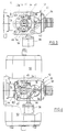
- FIG. 1 to 4 show a coupling in the coupled position with a coupling half 10 forming the fixed half and a coupling half 12 forming the loose half.
- the fixed half is connected, for example, to a stationary tube.
- the loose half is connected with a hose, for example.
- Both coupling halves 10, 12 have ball valve housings 14, 16 which support ball plugs (not shown).
- the ball valves are connected to switching shafts 18, 20.
- the construction of the ball valves 14, 16 should not be discussed in detail since it is conventional.
- the coupling halves 10, 12 have on the facing end faces in cross-section wedge-shaped circumferential ribs or collars which form wedge surfaces from the end face.
- a connecting and separating device has jaw-like clamping brackets 22, 24 which have a groove which is trapezoidal in cross section and which corresponds in its overall cross section to that of the bundles. If the clamping brackets 22, 24 are moved towards one another, the coupling halves 10, 12 are pressed axially against one another and firmly coupled to one another. With the coupling half 10 guide projections 26, 28 are firmly connected, which cooperate with guide surfaces of the coupling half 12, to orient the coupling halves 10, 12 in the direction of rotation when moving them towards one another and also to center them.
- Bearing pins 30, 32 extend through bores in the clamping bracket 22, 24 and through a bore in the guide projections 26, 28. They are screwed into a yoke 34. Nuts are screwed onto the other end of the pins 30, 32. Two helical springs sit on each pin on opposite sides of the guide projection 26, 28 and engage in corresponding blind bores in the brackets 22, 24 in order to bias them away from the projections 26, 28. With the yoke 34, an adjusting cylinder 36 is fixedly connected, which acts with a rod 38 on the clamping bracket 22 in order to pretension both against each other and to connect the coupling halves 10, 12.
- the clutch described is similar to the known clutch according to DE-GM 91 12 352.
- a clutch disc 40 is arranged in a rotationally fixed manner, the storage and structure of which will not be described in detail.
- a clutch pin 42 is seated on the clutch disk 40, which engages in an arcuate slot 44 of a first cam disk 46.
- the cam disk 46 is in rotational engagement with a sleeve 48 which can be driven by an adjustment drive 50 in opposite directions of rotation.
- a cam pin 52 projecting downward is connected to the cam disk 46.
- the cam disk 46 holds two telescopically nested sleeves 54, 56 which movably support a pressure pin 58 and which is biased by a spring 60 in the direction away from the disk 40.
- the pressure pin 58 engages in a coupling recess 62 of the disk 40.
- a bracket 62b is connected to a bearing plate 62a on the fixed half 10, which supports the servo drive 50, which partially extends with an upper section parallel to the cam disk 46 and forms a lower cam surface which presses it down when it engages with the pressure pin 58 into the clutch recess 62 of the disk 40.
- a second cam disk 64 is non-rotatably seated on the control shaft 20.
- a limiting pin 66 limits the rotation of the cam disk 64 to a range of 90 °, which corresponds to the closed or open position of the ball valve 16.
- the cam disk 64 has a radial slot 66 as a driving section, in which the driving pin 42 of the cam disk 46 engages in the illustration according to FIG. 3. The cam disk 46 turns clockwise rotated, the second cam 64 is rotated counterclockwise at the same time.
- the actuation of the ball valves 14, 16 proceeds as follows. In Fig. 3 the ball valves of the ball valves 14, 16 are in the closed position and in Fig. 4 in the open position. If the ball valves 14, 16 are to be closed, the control shaft 18 is set in rotation. During the first 90 ° rotation (first driving path), the cam disk 64 is synchronously rotated counterclockwise, so that the ball valve 16 is opened. The ball valve 14 remains closed, however, because a coupling of the cam disk 46 with the control shaft 18 cannot take place via the pin 42, because the latter moves in the slot 44 during the first driving path. If the control shaft 18 is rotated by a further 90 ° (second travel path), the second ball valve 14 is also brought into the open position.
- the pressure pin 58 is located above the clutch recess 62 of the clutch disc 40. During the second driving path, the pressure pin 58 is pressed down into the recess 58 by the lower cam surface of the bracket 62b.
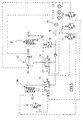
- a limit switch E2 is assigned to the adjustment drive 36 and two limit switches E3 and E4 are assigned to the adjustment drive 50.
- the drives 36, 50 are powered by a compressed air source 70 via electromagnetic directional valves 72, 74 operated.
- a tear-off device 76 measures the train, for example of a hose, with which the loose half 12 is connected. If this train exceeds a predetermined value, a limit switch E5 is actuated.
- the fixed half 10 is assigned a limit switch E1, which is actuated when the loose half 12 docks on the fixed half 10.
- a pressure switch D1 is assigned to line 78 to valves 72, 84 and responds when the pressure in line 78 falls below a predetermined value.
- three pushbuttons T1, T2, T3 and three lights L1, L2 and L3 are provided.
- the control circuit shown in Fig. 5 operates as follows.
- the switch E1 responds and automatically triggers the actuation of the second adjustment drive 36, so that the connection and disconnection device shown in FIGS. 1 to 4 is carried out, ie the yoke 34 is actuated to radially move the clamps 22, 24 together and to brace both coupling halves together.
- switch E2 responds. He now releases the actuation of the first drive 50 in order to bring the ball valves 14, 16 into the open position. This is done via the Push button switch T1. If the ball valves 14, 16 are in the open position, the switch E3 responds. In this way, it blocks the actuation of the adjustment drive 36 by the pushbutton switch T3.
- the lights L1, L2 and L3 indicate when the actuator 36 has been used to lock the ball valves or when the ball valves are in the closed or open position.
- a signal from the switch E5 causes the adjustment drive 50 to be actuated first, for example by actuating the switch T2. Subsequently, the second adjustment drive 36 is automatically actuated in order to unlock the coupling halves 14, 16.
- the pressure switch D1 responds, ie indicates that there is a risk that the ball valves 14, 16 can no longer be closed via the drive 50. For example, if the pressure of the pressure source 70 is 6 bar, the pressure switch speaks D1 on when there is only a pressure of 4 bar in line 78.
- the system works in the same way as with the breakaway device.
- the spring preloads in the adjusting drives 36, 50 ensure that the ball valves are closed and - subsequently, if necessary - the coupling halves 14, 16 can be unlocked.
Abstract
Description
Die Erfindung bezieht sich auf eine Kupplung zur Verbindung eines feststehenden Rohres mit einem beweglichen Rohr oder Schlauch nach dem Oberbegriff des Patentanspruchs 1.The invention relates to a coupling for connecting a fixed tube to a movable tube or hose according to the preamble of
Aus der DE 36 02 775 oder dem DE-GM 91 12 352 ist eine Kupplung der genannten Art bekanntgeworden, bei der jede Kupplungshälfte als Kugelhahn ausgeführt ist. Die Kupplungshälften stoßen so aneinander, daß kein Totraum zwischen den Kupplungshälften gebildet ist, wenn die Kugelküken in Schließstellung sind. Dies bedingt, daß die Kugeln ineinandergreifen, eine mithin kugelige Ausnehmung aufweist, in die die Kugel des benachbarten Hahns eingreift. Bei den bekannten Kupplungen sind mit den Schaltwellen der Kugelhähne Nockenscheiben verbunden, die zusammenwirken und sicherstellen, daß die Schaltwellen zeitlich nur nacheinander betätigt werden können. Würde eine derartige Maßnahme nicht vorgesehen, könnte es zu einem Blockieren der Kugelküken kommen und vor allen Dingen zu einer Beschädigung. Bei den bekannten Kupplungen ist indessen erforderlich, mit einem geeigneten Werkzeug oder einem Servoantrieb getrennt an die einzelnen Schaltwellen zu gehen. Dies ist jedoch verhältnismäßig umständlich und überfordert zuweilen das Bedienungspersonal.From DE 36 02 775 or DE-GM 91 12 352 a coupling of the type mentioned has become known, in which each coupling half is designed as a ball valve. The coupling halves abut each other so that no dead space is formed between the coupling halves when the ball valves are in the closed position. This means that the balls interlock, a spherical recess has, in which the ball of the adjacent tap engages. In the known couplings, cam disks are connected to the switching shafts of the ball valves, which interact and ensure that the switching shafts can only be actuated one after the other. If such a measure were not provided, the ball chicks could be blocked and, above all, could be damaged. In the known clutches, however, it is necessary to go separately to the individual switching shafts with a suitable tool or a servo drive. However, this is relatively cumbersome and sometimes overwhelms the operating personnel.
Aus der US 5 083 588 ist eine Kupplung bekanntgeworden, deren Absperrorgane als Kugelhähne ausgebildet sind, die totraumfrei zusammenwirken. Ein Kugelküken weist eine kugelabschnittförmige Vertiefung auf, in die das andere Kugelküken in der Schließstellung eingreift. Eine Betätigung der beiden Kugelhähne bei geschlossener Kupplung ist nur nacheinander möglich. Zu diesem Zweck weist eine Kupplungshälfte eine Hülse auf, die auf das zylindrische Gehäuse der anderen Kupplungshälfte geschoben wird. Die Kugelküken wirken auf gegenüberliegenden Seiten mit Schaltwellen zusammen, und jede Schaltwelle ist mit einer Nockenscheibe versehen. Werden die Kupplungshälften zusammengebracht, betätigt die Hülse über Betätigungsstifte die Nockenscheiben nacheinander. Beim Trennen der Kupplung wird ebenfalls ein sequentielles Schließen der Kugelhähne durchgeführt. In der Verbindungsstellung sind die Schaltwellen der Kugelhähne durch die Hülse verdeckt. Bei der bekannten Kupplung können daher die Kugelhähne während der Verbindung der Kupplungshälften nicht betätigt werden, um die Leitungsverbindung zu sperren. Die bekannte Kupplung erfordert einen Verstellantrieb zur Betätigung z.B. der losen Kupplungshälfte relativ zur Festhälfte, um die Kupplungshälften zu verbinden und das beschriebene Öffnen bzw. Schließen der Kugelhähne zu bewerkstelligen. Zusammenwirkende Führungen sorgen dafür, daß die Kupplungshälften genau axial ausgerichtet sind, damit eine Verbindung zustande kommt. Im übrigen erfordert die bekannte Kupplung, daß der Verstellantrieb zum Verbinden der Kupplungshälften miteinander an der Loshälfte sitzt.A coupling has become known from US Pat. No. 5,083,588, the shut-off elements of which are designed as ball valves which cooperate without dead space. A ball plug has a recess in the form of a spherical segment, in which the other ball plug engages in the closed position. The two ball valves can only be actuated one after the other when the clutch is closed. For this purpose, one coupling half has a sleeve which is pushed onto the cylindrical housing of the other coupling half. The ball valves interact on opposite sides with selector shafts, and each selector shaft has a cam disc Mistake. If the coupling halves are brought together, the sleeve actuates the cam disks in succession via actuating pins. When the clutch is disconnected, the ball valves are also closed sequentially. In the connecting position, the switching shafts of the ball valves are covered by the sleeve. In the known coupling, therefore, the ball valves cannot be actuated during the connection of the coupling halves in order to block the line connection. The known coupling requires an adjustment drive for actuating, for example, the loose coupling half relative to the fixed half in order to connect the coupling halves and to accomplish the described opening or closing of the ball valves. Co-operating guides ensure that the coupling halves are aligned exactly axially so that a connection is made. For the rest, the known coupling requires that the adjustment drive for connecting the coupling halves to one another sits on the loose half.
Der Erfindung liegt daher die Aufgabe zugrunde, die Kugelhähne der gattungsgemäßen Kupplung über eine einzige Drehbetätigung öffnen und schließen zu können.The invention is therefore based on the object of being able to open and close the ball valves of the generic coupling by means of a single rotary actuation.
Diese Aufgabe wird erfindungsgemäß gelöst durch die Merkmale des Patentanspruchs 1.This object is achieved according to the invention by the features of
Bei der erfindungsgemäßen Kupplung ist die mit einer Schaltwelle verbundene Nockenscheibe mit einem Mitnehmerabschnitt versehen, der mit einem Mitnabmeabschnitt der zweiten Nockenscheibe so zusammenwirkt, daß die zweite Nockenscheibe bei Drehung der ersten Nockenscheibe um einen ersten Mitnahmeweg in beiden Richtungen von der Nockenscheibe mitgenommen wird. Während des ersten Mitnahmewegs wird mithin der zweite Kugelhahn geöffnet bzw. geschlossen. Die zweite Nockenscheibe legt noch einen zweiten Mitnahmeweg zurück und ist während dieses Mitnahmewegs in beiden Richtungen mit der Schaltwelle des ersten Kugelhahns gekoppelt. Während des ersten Mitnahmewegs ist jedoch die erste Nockenscheibe von der zugehörigen Schaltwelle entkoppelt. Die erste Nockenscheibe legt daher einen größeren Weg als die zweite Nockenscheibe zurück. Bei einer Verstellung der Kugelküken von der Schließin die Öffnungsstellung und umgekehrt ist eine 90°-Drehung erforderlich. Die erste Nockenscheibe legt daher einen Weg von 180° zurück, wobei sie während der Drehung entlang des ersten Mitnahmewegs lediglich die zweite Nockenscheibe betätigt und nur während des zweiten Mitnahmewegs die zugehörige Schaltwelle verdreht. Auf diese Weise ist ein Getriebe vorgesehen, das eine sequentielle Betätigung der beiden Kugelhähne ermöglicht dergestalt, daß sie einander nicht blockieren und eine Beschädigung der Kugelküken vermieden ist.In the clutch according to the invention, the cam disk connected to a selector shaft is provided with a driver section which interacts with a cam section of the second cam disk in such a way that the second cam disk is taken along by the cam disk in both directions when the first cam disk rotates by a first driving path. The second ball valve is therefore opened or closed during the first travel path. The second cam disc covers a second travel path and is coupled in both directions to the switching shaft of the first ball valve during this travel path. During the first travel path, however, the first cam disk is decoupled from the associated shift shaft. The first cam disk therefore travels a larger distance than the second cam disk. When the ball valve is moved from the closed to the open position and vice versa, a 90 ° turn is required. The first cam disc therefore travels a distance of 180 °, wherein it only actuates the second cam disc during the rotation along the first driving path and only rotates the associated control shaft during the second driving path. In this way, a gear is provided which allows sequential actuation of the two ball valves so that they are each other do not block and damage to the ball valve is avoided.
Es sind verschiedene konstruktive Verwirklichungen der Erfindung denkbar. Im Hinblick auf den Mitnehmerabschnitt sieht eine Ausgestaltung der Erfindung vor, daß ein Mitnehmerstift an der ersten Nockenscheibe mit einem radialen Schlitz der zweiten Nockenscheibe zusammenwirkt. Lediglich während des ersten Mitnahmewegs ist der Mitnehmerstift im Mitnahmeschlitz der zweiten Nockenscheibe. Wird die erste Nockenscheibe weitergedreht, entfernt sich der Mitnehmerstift aus dem Mitnahmeschlitz. In der Schließstellung beider Kugelhähne erstreckt sich die Achse des Mitnahmeschlitzes annähernd senkrecht zur Linie, der sich durch die Mitte der ersten Nockenscheibe und durch ihren Mitnehmerstift erstreckt. Auf diese Weise ist die zweite Nockenscheibe wirksam verriegelt, und ein Ergreifen der zweiten Nockenscheibe zur Betätigung der Schaltwelle des zweiten Kugelhahns auf gewollte oder unbeabsichtigte Art und Weise ist vermieden.Various constructive realizations of the invention are conceivable. With regard to the driver section, an embodiment of the invention provides that a driver pin on the first cam disk interacts with a radial slot of the second cam disk. The driving pin is only in the driving slot of the second cam disk during the first driving path. If the first cam disc is turned further, the driver pin is removed from the driver slot. In the closed position of both ball valves, the axis of the driving slot extends approximately perpendicular to the line, which extends through the center of the first cam disk and through its driving pin. In this way, the second cam disc is effectively locked and gripping the second cam disc to actuate the switching shaft of the second ball valve in an intentional or unintentional manner is avoided.
Nach einer Ausgestaltung der Erfindung wird die freie Drehbarkeit der ersten Nockenscheibe relativ zur zugehörigen Schaltwelle dadurch erreicht, daß sich ein Kupplungsstift, der mit der Schaltwelle verbunden ist, durch einen kreisbogenförmigen Schlitz in der ersten Nockenscheibe erstreckt. Während einer ersten Betätigung kommt der Kupplungsstift an das Ende des Schlitzes an. Wird jedoch die erste Nockenscheibe weitergedreht, nimmt die erste Nockenscheibe die Schaltwelle mit. Bei der umgekehrten Bewegung würde wegen des Zusammenwirkens von Schlitz und Stift die Schaltwelle unbetätigt bleiben. Daher ist außerdem ein zweites Kupplungsmittel vorgesehen, welches in der entgegengesetzten Drehrichtung Schaltwelle und erste Nockenscheibe kuppelt, bis der erste Mitnahmeweg erreicht ist. Dies geschieht nach einer Ausgestaltung der Erfindung etwa dadurch, daß der Kupplungsstift auf einer auf der Schaltwelle sitzenden Kupplungsscheibe angebracht ist, die eine Kupplungsausnehmung aufweist, an der ersten Nockenscheibe ein federnd gelagerter Druckstift vorgesehen ist, der während des zweiten Mitnahmewegs zur Kupplungsausnehmung ausgerichtet ist und durch Betätigung von einer Nockenfläche in diese eingreift.According to one embodiment of the invention, the free rotation of the first cam disk relative to the associated shift shaft is achieved in that a coupling pin, which is connected to the shift shaft, by a arcuate slot extends in the first cam. During a first actuation, the coupling pin arrives at the end of the slot. However, if the first cam disc is turned further, the first cam disc takes the selector shaft with it. In the reverse movement, the switching shaft would remain unactuated due to the interaction of the slot and pin. Therefore, a second coupling means is also provided, which couples the control shaft and the first cam disk in the opposite direction of rotation until the first driving path is reached. According to one embodiment of the invention, this is done, for example, in that the coupling pin is mounted on a clutch disc seated on the selector shaft, which has a clutch recess, and a spring-mounted pressure pin is provided on the first cam disc, which is aligned with the clutch recess during the second driving path and through Actuation of a cam surface engages in this.
Bei der erfindungsgemäßen Kupplung kann die Loshälfte bildende Kupplungshälfte von Hand erfaßt und gegen die Festhälfte bildende Kupplungshälfte angesetzt werden. Durch das Vorsehen geeigneter Steuervorkehrungen kann dann im Anschluß automatisch das Verriegeln der Kupplungshälften und das Öffnen der Kugelhähne durchgeführt werden, indem ein erster Antrieb vorzugsweise der Festhälfte zugeordnet ist zur Betätigung der zugehörigen Schaltwelle sowie ein zweiter Verstellantrieb, der eine geeignete Verbindungs- und Trennvorrichtung betätigt, um die beiden Kupplungshälften miteinander zu verriegeln. So kann eine der Kupplungshälften einen Schalter aufweisen, bei dessen Betätigung der zweite Verstellantrieb betätigt wird, um die Kupplungshälften miteinander zu verriegeln. Sobald die Verriegelung stattgefunden hat, wird ein zweiter Schalter betätigt, der nunmehr die Betätigung des ersten Verstellantriebs freigibt. Danach kann zum Beispiel mit Hilfe eines Tastschalters das Öffnen beider Kugelhähne in Folge durchgeführt werden. Sobald dies geschehen ist, ist ein dritter Schalter betätigbar, der verhindert, daß ein Trennen der Kupplungshälften stattfindet, was über einen weiteren Tastschalter zum Beispiel in Gang gesetzt werden kann, aber nur, wenn zunächst der zweite Verstellantrieb betätigt worden ist. Ein vierter Schalter stellt dies fest, so daß das Trennen der Kupplungshälften durch Entriegeln über den zweiten Verstellantrieb stattfinden kann.In the coupling according to the invention, the coupling half forming the loose half can be gripped by hand and placed against the coupling half forming the fixed half. By providing suitable control measures, the locking of the coupling halves and the opening of the ball valves can then be carried out automatically by a first drive is preferably assigned to the fixed half for actuating the associated shift shaft and a second adjustment drive which actuates a suitable connecting and disconnecting device in order to lock the two coupling halves together. For example, one of the coupling halves can have a switch, the actuation of which actuates the second adjustment drive in order to lock the coupling halves together. As soon as the locking has taken place, a second switch is actuated, which now releases the actuation of the first adjustment drive. Then, for example, using a pushbutton switch, both ball valves can be opened in succession. As soon as this has been done, a third switch can be actuated, which prevents the coupling halves from separating, which can be started by means of a further pushbutton switch, for example, but only if the second adjustment drive has been actuated first. A fourth switch detects this, so that the coupling halves can be separated by unlocking via the second adjustment drive.
Die beschriebene Steuervorrichtung kann auch mit einer sogenannten Abreißsicherung zusammenwirken, die zum Beispiel den Zug mißt, der an der Leitung bzw. dem Schlauch wirkt, an dem eine Kupplungshälfte befestigt ist. Übersteigt dieser Zug einen vorgegebenen Wert, ist es zweckmäßig, wenn die Kupp-lungshälften getrennt werden. Die Zugsicherung erzeugt ein Signal, wodurch der erste Verstellantrieb betätigt wird. Erst danach kann ein weiteres Signal zum Trennen der Kupp-lung über den zweiten Verstellantrieb erzeugt werden.The control device described can also cooperate with a so-called tear-off safeguard, which measures, for example, the train acting on the line or the hose to which a coupling half is attached. Exceeds this train a predetermined value, it is appropriate if the coupling halves are separated. The train protection generates a signal, which actuates the first adjustment drive. Only then can another signal for disconnecting the clutch be generated via the second adjustment drive.
Ein Ausführungsbeispiel der Erfindung wird nachfolgend anhand von Zeichnungen näher erläutert.
- Fig. 1
- zeigt die Seitenansicht teilweise im Schnitt einer Kupplung nach der Erfindung.
- Fig. 2
- zeigt einen Schnitt durch die Darstellung nach Fig. 1 entlang der Linie 2-2.
- Fig. 3
- zeigt einen Schnitt durch die Darstellung nach Fig. entlang der Linie 3-3 in der Schließstellung der Kugelhähne.
- Fig. 4
- zeigt eine ähnliche Ansicht wie Fig. 3 in der Öffnungstellung der Kugelhähne.
- Fig. 5
- zeigt schematisch ein Schaltschema zur elektropneumatischen Steuerung der Kupplung nach den
Figuren 1 bis 4.
- Fig. 1
- shows the side view partly in section of a coupling according to the invention.
- Fig. 2
- shows a section through the representation of FIG. 1 along the line 2-2.
- Fig. 3
- shows a section through the representation of Fig. Along the line 3-3 in the closed position of the ball valves.
- Fig. 4
- shows a view similar to Fig. 3 in the open position of the ball valves.
- Fig. 5
- shows schematically a circuit diagram for electropneumatic control of the clutch according to Figures 1 to 4.
In den Figuren 1 bis 4 ist eine Kupplung in gekuppelter Stellung dargestellt mit einer die Festhälfte bildenden Kupplungshälfte 10 und einer die Loshälfte bildenden Kupplungshälfte 12. Die Festhälfte ist zum Beispiel mit einem stationären Rohr verbunden. Die Loshälfte ist zum Beispiel mit einem Schlauch verbunden. Beide Kupplungshälften 10, 12 weisen Kugelhahngehäuse 14, 16 auf, die Kugelküken lagern (nicht gezeigt). Die Kugelküken sind mit Schaltwellen 18, 20 verbunden. Auf den Aufbau der Kugelhähne 14, 16 soll nicht im einzelnen eingegangen werden, da er konventionell ist.1 to 4 show a coupling in the coupled position with a
Wie lediglich in Fig. 2 angedeutet, weisen die Kupplungshälften 10, 12 an den einander zugekehrten Stirnseiten im Querschnitt keilförmig umlaufende Rippen oder Bunde auf, die von der Stirnseite fort Keilflächen bilden. Eine Verbindungs- und Trennvorrichtung weist backenartige Klemmbügel 22, 24 auf, die eine im Querschnitt trapezförmige Nut aufweisen, die im Gesamtquerschnitt dem der Bunde entspricht. Werden die Klemmbügel 22, 24 aufeinander zu bewegt, werden die Kupplungshälften 10, 12 axial aneinandergepreßt und fest miteinander gekuppelt. Mit der Kupplungshälfte 10 sind Führungsvorsprünge 26, 28 fest verbunden, welche mit Führungsflächen der Kupplungshälfte 12 zusammenwirken, um die Kupplungshälften 10, 12 beim Aufeinanderzubewegen in Drehrichtung zu orientieren und außerdem zu zentrieren. Lagerstifte 30, 32 erstrecken sich durch Bohrungen der Klemmbügel 22, 24 sowie durch eine Bohrung der Führungsvorsprünge 26, 28. Sie sind in einem Joch 34 eingeschraubt. Auf das andere Ende der Stifte 30, 32 sind Muttern geschraubt. Auf jedem Stift sitzen zwei Schraubenfedern auf gegenüberliegenden Seiten des Führungsvorsprungs 26, 28 und greifen in entsprechende Sackbohrungen der Bügel 22, 24 ein, um diese von den Vorsprüngen 26, 28 fort vorzuspannen. Mit dem Joch 34 ist ein Verstellzylinder 36 fest verbunden, der mit einer Stange 38 auf den Klemmbügel 22 wirkt, um beide gegeneinander vorzuspannen und die Kupplungshälften 10, 12 zu verbinden.As only indicated in Fig. 2, the coupling halves 10, 12 have on the facing end faces in cross-section wedge-shaped circumferential ribs or collars which form wedge surfaces from the end face. A connecting and separating device has jaw-
Insoweit gleicht die beschriebene Kupplung der bekannten Kupplung nach dem DE-GM 91 12 352.In this respect, the clutch described is similar to the known clutch according to DE-GM 91 12 352.
Auf der Schaltwelle 18 für den Kugelhahn 14 ist drehfest eine Kupplungsscheibe 40 angeordnet, deren Lagerung und Aufbau im einzelnen nicht beschrieben werden soll. Wie aus Fig. 2 hervorgeht, sitzt auf der Kupplungsscheibe 40 ein Kupplungsstift 42, der in einen kreisbogenförmigen Schlitz 44 einer ersten Nockenscheibe 46 eingreift. Die Nockenscheibe 46 steht in Dreheingriff mit einer Hülse 48, die von einem Verstellantrieb 50 in entgegengesetzten Drehrichtungen antreibbar ist. Mit der Nockenscheibe 46 ist ein nach unten ragender Mitnehmerstift 52 verbunden. Die Nockenscheibe 46 hält zwei teleskopisch ineinandergesteckte Hülsen 54, 56, die einen Druckstift 58 beweglich lagern und der von einer Feder 60 in Richtung von der Scheibe 40 fort vorgespannt ist. In der Darstellung nach Fig. 2 greift der Druckstift 58 in eine Kupplungsausnehmung 62 der Scheibe 40.On the switching
Mit einer Lagerplatte 62a auf der Festhälfte 10, welche den Servoantrieb 50 lagert, ist ein Bügel 62b verbunden, der sich teilweise mit einem oberen Abschnitt parallel zur Nockenscheibe 46 erstreckt und eine untere Nockenfläche bildet, die bei Eingriff mit dem Druckstift 58 diesen nach unten drückt in die Kupplungsausnehmung 62 der Scheibe 40.A
Eine zweite Nockenscheibe 64 sitzt drehfest auf der Schaltwelle 20. Ein Begrenzungsstift 66 begrenzt die Drehung der Nockenscheibe 64 auf einen Bereich von 90°, was der Schließ- bzw. Öffnungsstellung des Kugelhahns 16 entspricht. Die Nockenscheibe 64 weist einen radialen Schlitz 66 als Mitnahmeabschnitt auf, in den bei der Darstellung nach Fig. 3 der Mitnehmerstift 42 der Nockenscheibe 46 eingreift. Wird die Nockenscheibe 46 im Uhrzeigersinn gedreht, wird gleichzeitig die zweite Nockenscheibe 64 entgegengesetzt dem Uhrzeigersinn verdreht.A
Die Betätigung der Kugelhähne 14, 16 läuft wie folgt ab. In Fig. 3 sind die Kugelküken der Kugelhähne 14, 16 in Schließstellung und in Fig. 4 in Öffnungsstellung. Sollen die Kugelhähne 14, 16 geschlossen werden, wird die Schaltwelle 18 in Drehung versetzt. Während der ersten 90°-Drehung (erster Mitnahmeweg) wird synchron die Nockenscheibe 64 entgegengesetzt dem Uhrzeigersinn verdreht, so daß der Kugelhahn 16 geöffnet wird. Der Kugelhahn 14 bleibt indessen geschlossen, weil eine Kopplung der Nockenscheibe 46 mit der Schaltwelle 18 über den Stift 42 nicht zustande kommen kann, weil dieser sich während des ersten Mitnahmeweges im Schlitz 44 bewegt. Wird die Schaltwelle 18 um weitere 90° gedreht (zweiter Mitnahmeweg), wird auch der zweite Kugelhahn 14 in Öffnungsstellung gebracht. In dem Augenblick, in dem der erste Mitnahmeweg beendet wurde, befindet sich der Druckstift 58 über der Kupplungsausnehmung 62 der Kupplungsscheibe 40. Während des zweiten Mitnahmewegs wird der Druckstift 58 durch die untere Nockenfläche des Bügels 62b nach unten gedrückt in die Ausnehmung 58 hinein.The actuation of the
Sollen die Kugelhähne 14, 16 wieder in die Schließstellung gebracht werden, wird die erste Nockenscheibe 46 entgegengesetzt dem Uhrzeigersinn verdreht. Während des ersten Verstellweges über 90° (zweiter Mitnahmeweg) wird der Kugelhahn 14 geöffnet, da die Scheibe 40 mit der Nockenscheibe 46 über den Druckstift 58 gekoppelt ist. Am Ende des zweiten Mitnahmewegs erfolgt eine Entkopplung, so daß die Nockenscheibe 46 sich während des ersten Mitnahmeweges frei drehen kann und in die in Fig. 3 gezeigte Stellung zurückgelangt.Shall the
Es versteht sich, daß eine Verriegelung zwischen der Betätigung der Bügel 22, 24 und der Öffnungs- bzw. der Schließbewegung der Kugelhähne 14, 16 vorgenommen werden muß, um sicherzustellen, daß die Kupplung nicht getrennt wird, während die Kugelhähne 14, 16 in Öffnungsstellung sind. Da der Verstellantrieb 50 und auch der Verstellantrieb für die Kupplung 36 hydraulisch ist, kann eine Verriegelung auf hydraulischem Wege bewerkstelligt werden.It is understood that a lock must be made between the actuation of the
In Fig. 5 sind der erste Verstellantrieb 50 nach den Figuren 1 bis 4 und der zweite Verstellantrieb 36 schematisch dargestellt. Dem Verstellantrieb 36 ist ein Endschalter E2 zugeordnet und dem Verstellantrieb 50 zwei Endschalter E3 und E4. Wie erkennbar, werden die Antriebe 36, 50 von einer Druckluftquelle 70 über elektromagnetische Wegeventile 72, 74 betätigt. Eine Abreißsicherung 76 mißt den Zug zum Beispiel eines Schlauches, mit dem die Loshälfte 12 verbunden ist. Übersteigt dieser Zug einen vorgegebenen Wert, wird ein Endschalter E5 betätigt.5, the
Der Festhälfte 10 ist ein Endschalter E1 zugeordnet, der betätigt wird, wenn die Loshälfte 12 an der Festhälfte 10 andockt. Ein Druckschalter D1 ist der Leitung 78 zu den Ventilen 72, 84 zugeordnet und spricht an, wenn der Druck in der Leitung 78 einen vorgegebenen Wert unterschreitet. Schließlich sind drei Tastschalter T1, T2, T3 und drei Leuchten L1, L2 und L3 vorgesehen. Die in Fig. 5 dargestellte Steuerschaltung arbeitet wie folgt.The fixed
Wird die Loshälfte 12 an der Festhälfte 10 angedockt, spricht der Schalter E1 an und löst automatisch die Betätigung des zweiten Verstellantriebs 36 aus, so daß die in Verbindung mit der in den Figuren 1 bis 4 dargestellten Verbindungs- und Trennvorrichtung durchgeführt wird, d.h. das Joch 34 betätigt wird, um die Klemmbügel 22, 24 radial zusammenzufahren und beide Kupplungshälften miteinander zu verspannen. Sobald diese Verriegelungsstellung erreicht ist, spricht der Schalter E2 an. Er gibt nunmehr die Betätigung des ersten Antriebs 50 frei, um die Kugelhähne 14, 16 in Öffnungsstellung zu bringen. Dies erfolgt über den Tastschalter T1. Sind die Kugelhähne 14, 16 in Öffnungsstellung, spricht der Schalter E3 an. Er sperrt auf diese Weise die Betätigung des Verstellantriebs 36 durch den Tastschalter T3. Sollen die Kugelhähne 14, 16 wieder in Schließstellung gebracht werden, erfolgt dies über den Tastschalter T2. Nach Beendigung der Verstellung spricht der Schalter E4 an, so daß nunmehr die Betätigung der Entriegelung über den Verstellantrieb 36 mit Hilfe des Tastschalters T3 vor sich gehen kann.If the
Die Leuchten L1, L2 und L3 zeigen an, wenn mit Hilfe des Verstellantriebs 36 eine Verriegelung erfolgt ist bzw. die Kugelhähne in der Schließ- bzw. Öffnungsstellung sind.The lights L1, L2 and L3 indicate when the
Spricht die Abreißsicherung 76 an, verursacht ein Signal vom Schalter E5, daß zunächst der Verstellantrieb 50 betätigt wird, beispielsweise über eine Betätigung des Schalters T2. Im Anschluß daran erfolgt automatisch eine Betätigung des zweiten Verstellantriebs 36, um eine Entriegelung der Kupplungshälften 14, 16 zu bewerkstelligen. Der gleiche Vorgang läuft ab, wenn der Druckschalter D1 anspricht, d.h. anzeigt, daß Gefahr besteht, daß ein Schließen der Kugelhähne 14, 16 über den Antrieb 50 nicht mehr stattfinden kann. Ist zum Beispiel der Druck der Druckquelle 70 6 bar, spricht zum Beispiel der Druckschalter D1 an, wenn in der Leitung 78 nur noch ein Druck von 4 bar herrscht.If the tear-off device 76 responds, a signal from the switch E5 causes the
Falls ein Strom- und/oder ein Druckausfall vorkommt, was über die elektrische Versorgung bzw. den Druckschalter D1 festgestellt wird, arbeitet das System auf gleiche Weise wie bei der Abreißsicherung. Die Federvorspannungen in den Verstellantrieben 36, 50 sorgen dafür, daß die Kugelhähne geschlossen werden und - anschließend, falls erforderlich - die Entriegelung der Kupplungshälften 14, 16 stattfinden kann.If there is a power and / or pressure failure, which is determined via the electrical supply or the pressure switch D1, the system works in the same way as with the breakaway device. The spring preloads in the adjusting drives 36, 50 ensure that the ball valves are closed and - subsequently, if necessary - the coupling halves 14, 16 can be unlocked.
Claims (8)
Applications Claiming Priority (2)
| Application Number | Priority Date | Filing Date | Title |
|---|---|---|---|
| DE4218372 | 1992-06-04 | ||
| DE19924218372 DE4218372C1 (en) | 1992-06-04 | 1992-06-04 | Coupling for connecting a fixed pipe to a moving pipe or hose |
Publications (1)
| Publication Number | Publication Date |
|---|---|
| EP0572931A1 true EP0572931A1 (en) | 1993-12-08 |
Family
ID=6460340
Family Applications (1)
| Application Number | Title | Priority Date | Filing Date |
|---|---|---|---|
| EP93108627A Withdrawn EP0572931A1 (en) | 1992-06-04 | 1993-05-28 | Coupling for the connection of a fixed pipe to a movable pipe or hose |
Country Status (2)
| Country | Link |
|---|---|
| EP (1) | EP0572931A1 (en) |
| DE (1) | DE4218372C1 (en) |
Cited By (1)
| Publication number | Priority date | Publication date | Assignee | Title |
|---|---|---|---|---|
| US5488972A (en) * | 1995-02-13 | 1996-02-06 | Aeroquip Corporation | Ball valve coupling |
Families Citing this family (1)
| Publication number | Priority date | Publication date | Assignee | Title |
|---|---|---|---|---|
| DE4419545C1 (en) * | 1994-06-03 | 1996-02-22 | Pfannenschmidt Erhard | Device for switching two fittings together |
Citations (3)
| Publication number | Priority date | Publication date | Assignee | Title |
|---|---|---|---|---|
| GB2162270A (en) * | 1984-07-27 | 1986-01-29 | Flow Engineering Limited Sa | Emergency release couplers |
| EP0463197A1 (en) * | 1988-12-30 | 1992-01-02 | Robert Von Keitz Kg | Disconnectable double valve |
| DE9112352U1 (en) * | 1991-06-10 | 1992-02-27 | Pfannenschmidt, Erhard, 2000 Hamburg, De |
Family Cites Families (2)
| Publication number | Priority date | Publication date | Assignee | Title |
|---|---|---|---|---|
| DE3602775A1 (en) * | 1986-01-30 | 1987-08-20 | Pfannenschmidt Erhard | Coupling for connecting a fixed pipe or the like to a movable pipe or hose |
| FR2662230B1 (en) * | 1990-05-18 | 1992-10-16 | Staubli Sa Ets | COUPLING DEVICE WITH ROTATING BEAMS FOR PIPING. |
-
1992
- 1992-06-04 DE DE19924218372 patent/DE4218372C1/en not_active Expired - Fee Related
-
1993
- 1993-05-28 EP EP93108627A patent/EP0572931A1/en not_active Withdrawn
Patent Citations (3)
| Publication number | Priority date | Publication date | Assignee | Title |
|---|---|---|---|---|
| GB2162270A (en) * | 1984-07-27 | 1986-01-29 | Flow Engineering Limited Sa | Emergency release couplers |
| EP0463197A1 (en) * | 1988-12-30 | 1992-01-02 | Robert Von Keitz Kg | Disconnectable double valve |
| DE9112352U1 (en) * | 1991-06-10 | 1992-02-27 | Pfannenschmidt, Erhard, 2000 Hamburg, De |
Cited By (1)
| Publication number | Priority date | Publication date | Assignee | Title |
|---|---|---|---|---|
| US5488972A (en) * | 1995-02-13 | 1996-02-06 | Aeroquip Corporation | Ball valve coupling |
Also Published As
| Publication number | Publication date |
|---|---|
| DE4218372C1 (en) | 1993-10-28 |
Similar Documents
| Publication | Publication Date | Title |
|---|---|---|
| EP0164091A1 (en) | Device for coupling or uncoupling a tool support to/from a manipulator | |
| DE102011008601B4 (en) | Manual robot tool changer with quick coupling mechanism | |
| WO2018033235A2 (en) | Device for detachably securing modules | |
| EP0963688B1 (en) | Working machine | |
| WO1983003082A1 (en) | Device for locking the rotation of a steering column | |
| DE60101730T2 (en) | LOCKING MECHANISM | |
| DE2835879A1 (en) | DRIVE CONNECTION BETWEEN AN OPTIONAL HANDLE AND A MOTOR DRIVE ON ONE SIDE AND A SPRING TENSION SHAFT ON THE OTHER SIDE IN THE OPERATING MECHANISM OF A SELF-SWITCH | |
| EP0442265B1 (en) | Clamping device for an axial movable actuator for the reversal of the gripper with a sheet-fed rotary letterpress | |
| EP0184799A2 (en) | Vent coupling | |
| EP1321344A1 (en) | Device for centering or lateral positioning of a central buffer coupling of a railway vehicle | |
| DE4419545C1 (en) | Device for switching two fittings together | |
| AT503556B1 (en) | Mutliface-coupling device for hydraulic lines, has blocking device associated with locking sleeve and engaging in region of movement of locking sleeve as blocking element in coupled position of coupling units | |
| DE3621951C2 (en) | ||
| DE4218372C1 (en) | Coupling for connecting a fixed pipe to a moving pipe or hose | |
| DE3905539A1 (en) | Remote-control device for blocking a bracing screw | |
| DE19641133A1 (en) | Changing device for shaft=hub connection | |
| EP0742063A1 (en) | Tool turret | |
| DE3410967C2 (en) | ||
| WO2022069177A1 (en) | Locking device and locking method for a switch point drive and switch point drive | |
| DE3220872C2 (en) | Actuating device for the optional manual or motorized operation of machines, especially small offset printing machines | |
| DE3520541C2 (en) | ||
| DE3941935C2 (en) | Turnbuckle | |
| DE1576075A1 (en) | Hydraulic actuation device | |
| DE19626178C2 (en) | Actuator for actuating an actuator | |
| DE3044807A1 (en) | PNEUMATIC-MECHANICAL VEHICLE BRAKE CYLINDER WITH A MECHANISM FOR UNLOCKING THE MECHANICAL BRAKE |
Legal Events
| Date | Code | Title | Description |
|---|---|---|---|
| PUAI | Public reference made under article 153(3) epc to a published international application that has entered the european phase |
Free format text: ORIGINAL CODE: 0009012 |
|
| AK | Designated contracting states |
Kind code of ref document: A1 Designated state(s): DE FR IT |
|
| STAA | Information on the status of an ep patent application or granted ep patent |
Free format text: STATUS: THE APPLICATION IS DEEMED TO BE WITHDRAWN |
|
| 18D | Application deemed to be withdrawn |
Effective date: 19940609 |