EP0572586B1 - Electromagnetic door lock assembly - Google Patents
Electromagnetic door lock assembly Download PDFInfo
- Publication number
- EP0572586B1 EP0572586B1 EP19920923462 EP92923462A EP0572586B1 EP 0572586 B1 EP0572586 B1 EP 0572586B1 EP 19920923462 EP19920923462 EP 19920923462 EP 92923462 A EP92923462 A EP 92923462A EP 0572586 B1 EP0572586 B1 EP 0572586B1
- Authority
- EP
- European Patent Office
- Prior art keywords
- electromagnet
- armature
- door
- plate
- power
- Prior art date
- Legal status (The legal status is an assumption and is not a legal conclusion. Google has not performed a legal analysis and makes no representation as to the accuracy of the status listed.)
- Expired - Lifetime
Links
- 230000003993 interaction Effects 0.000 claims abstract description 10
- 230000004044 response Effects 0.000 claims abstract description 10
- 230000008878 coupling Effects 0.000 claims abstract description 7
- 238000010168 coupling process Methods 0.000 claims abstract description 7
- 238000005859 coupling reaction Methods 0.000 claims abstract description 7
- 230000003111 delayed effect Effects 0.000 claims abstract 9
- 230000002708 enhancing effect Effects 0.000 claims description 9
- 230000003321 amplification Effects 0.000 claims 6
- 238000003199 nucleic acid amplification method Methods 0.000 claims 6
- 238000001514 detection method Methods 0.000 claims 4
- 125000006850 spacer group Chemical group 0.000 claims 1
- 239000003990 capacitor Substances 0.000 abstract description 14
- 230000009471 action Effects 0.000 description 3
- 230000000694 effects Effects 0.000 description 2
- 238000010008 shearing Methods 0.000 description 2
- 230000001276 controlling effect Effects 0.000 description 1
- 238000010586 diagram Methods 0.000 description 1
- 238000006073 displacement reaction Methods 0.000 description 1
- 239000000463 material Substances 0.000 description 1
- 238000000034 method Methods 0.000 description 1
- 229920001084 poly(chloroprene) Polymers 0.000 description 1
- 230000001105 regulatory effect Effects 0.000 description 1
- 238000000926 separation method Methods 0.000 description 1
- 230000000638 stimulation Effects 0.000 description 1
- 230000002459 sustained effect Effects 0.000 description 1
- 230000001960 triggered effect Effects 0.000 description 1
Images


Classifications
-
- E—FIXED CONSTRUCTIONS
- E05—LOCKS; KEYS; WINDOW OR DOOR FITTINGS; SAFES
- E05C—BOLTS OR FASTENING DEVICES FOR WINGS, SPECIALLY FOR DOORS OR WINDOWS
- E05C19/00—Other devices specially designed for securing wings, e.g. with suction cups
- E05C19/16—Devices holding the wing by magnetic or electromagnetic attraction
- E05C19/166—Devices holding the wing by magnetic or electromagnetic attraction electromagnetic
- E05C19/168—Devices holding the wing by magnetic or electromagnetic attraction electromagnetic a movable bolt being electromagnetically held in the striker by electromagnetic attraction
-
- Y—GENERAL TAGGING OF NEW TECHNOLOGICAL DEVELOPMENTS; GENERAL TAGGING OF CROSS-SECTIONAL TECHNOLOGIES SPANNING OVER SEVERAL SECTIONS OF THE IPC; TECHNICAL SUBJECTS COVERED BY FORMER USPC CROSS-REFERENCE ART COLLECTIONS [XRACs] AND DIGESTS
- Y10—TECHNICAL SUBJECTS COVERED BY FORMER USPC
- Y10T—TECHNICAL SUBJECTS COVERED BY FORMER US CLASSIFICATION
- Y10T292/00—Closure fasteners
- Y10T292/11—Magnetic
-
- Y—GENERAL TAGGING OF NEW TECHNOLOGICAL DEVELOPMENTS; GENERAL TAGGING OF CROSS-SECTIONAL TECHNOLOGIES SPANNING OVER SEVERAL SECTIONS OF THE IPC; TECHNICAL SUBJECTS COVERED BY FORMER USPC CROSS-REFERENCE ART COLLECTIONS [XRACs] AND DIGESTS
- Y10—TECHNICAL SUBJECTS COVERED BY FORMER USPC
- Y10T—TECHNICAL SUBJECTS COVERED BY FORMER US CLASSIFICATION
- Y10T292/00—Closure fasteners
- Y10T292/68—Keepers
- Y10T292/696—With movable dog, catch or striker
- Y10T292/699—Motor controlled
Definitions
- the present invention relates generally to electromagnetic door locking devices and particularly to shear locks having improved features which ensure that the lock operates rapidly and positively during both locking and unlocking operations.
- a shear lock comprises an electromagnet mounted to or in a frame defining a doorway.
- An armature is movably mounted to travel with a door as the door moves in the doorway between an "open” and “closed” position.
- the armature When the door is in the closed position, the armature is positioned in spaced relation from the electromagnet but is mounted to or in the door such that when power is applied to the electromagnet the armature responds to the magnetic field and becomes engaged on an adjacent surface of the electromagnet.
- shoulder means such as ledges, tangs and tabs have been employed to provide some physical interrelationship between the face of the electromagnet and the armature so as to enhance the lock's resistance to a shearing movement which would result from any attempt to open the door while power was applied to the electromagnet.
- the various styles of shoulder means have provided sufficient mechanical interaction that, upon the removal of power from the electromagnet, the armature has failed to release from the face of the electromagnet. Such failure to release can also occur due to residual magnetic fields remaining after the removal of power from the electromagnet, or other causes.
- biasing means can be provided. Particularly where the armature is mounted in or on the top of the door, this biasing means acts in addition to any gravitational action on the armature itself to enhance the disengagement of the armature and electromagnet upon removal of power from the electromagnet. Examples of known devices which include such biasing means are found in U.S. Patents 5,016,929 and 5,033,779.
- the additional disengagement force provided by the biasing means needs to be compensated for during the locking or engaging operation between the electromagnet and the armature. While it would seem to be possible to provide electromagnets of substantially increased size and field strength so as to overcome the additional force provided by the biasing means, such an electromagnet can be significantly more expensive to make and proportionately more difficult to install properly.
- GB-A-2 232 713 discloses an electromagnetic shear lock comprising an electromagnetic assembly for mounting to a doorway and an armature assembly for mounting in a door in a position to be attracted to the electromagnet.
- Spring means act on the armature to provide a return force on the armature when the armature is attracted to the electromagnet.
- an electromagnetic door locking assembly which includes appropriate biasing to ensure positive unlocking action between the armature and electromagnet and to provide appropriate means to ensure rapid positive locking operation despite the presence of the biasing means.
- an electromagnetic door lock assembly comprising: an electromagnet positioned in a frame adjacent to a door; an adjustable armature assembly positioned in the door for interaction with the electromagnet, the armature assembly including an armature plate and biasing means for biasing the armature plate away from the electromagnet; a backing plate situated adjacent to a back surface of the armature plate, coupling means for coupling the backing plate to the armature plate, said biasing means biasing the backing plate and armature plate towards each other; and power means for providing power to the electromagnet sufficient to hold the armature plate in contact with the electromagnet, characterised in that the power means includes enhancing means for developing an initial enhanced current through the electromagnet to provide armature plate attraction to the electromagnet against the added force provided by the biasing means.
- An electromagnetic door lock assembly comprises an electromagnet positioned at a fixed location with respect to a frame defining the doorway.
- An adjustable armature assembly is positioned to travel with the door mounted in the doorway to a position of interaction with the electromagnet when the door is closed.
- the armature assembly includes an armature plate and biasing means for biasing the armature plate away from the electromagnet so as to ensure positive disengagement of the armature from the electromagnet when power is removed from the electromagnet.
- the power means for providing power to the electromagnet includes an enhancing means for developing an initial enhanced current through the electromagnet to assure armature plate attraction to the electromagnet against the added force provided by the biasing means.
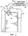
- An electromagnetic door lock assembly 10 is shown in Figure 1 in connection with a door 12 shown in a closed position closing a doorway defined by a frame 14 outlining the doorway opening in a wall 16.
- An adjustable armature assembly 18 is shown mounted to the top of the door 12 and positioned for interaction with an electromagnet 20 which is shown fixed in the top of frame 14.
- the electromagnet 20 is powered by a power circuit 22 described more fully in connection with Figure 7.
- the power circuit provides power to the electromagnet 20 through a power cable 24 only after the door 12 is sensed to be in a closed position as shown in Figure 1.
- the sensing is achieved by a magnetic sensor 26 positioned adjacent to the electromagnet and senses the magnetic field provided by a small permanent magnet 28 mounted in the top of the door adjacent to or as a part of the armature assembly 18.
- a signal is provided through a cable 30 to a sensor trigger circuit 32 which, after an appropriate time delay described later, causes a momentary application of an enhanced amount of current through the cable 24 to the electromagnet by an enhancing circuit 39.
- Other conventional controls for the power circuit are of course provided, but not illustrated.
- the electromagnet 20 comprises a coil potted in a housing 36 as shown in Figure 2.
- the housing includes mounting portions 38 at each end of the coil which are adapted to be secured to the frame 14 by screws or other similar means.
- the electromagnet includes a lower face 40 adapted to the contact by the armature when power is applied to the coil through the power cable 24. Shoulder means in the form of elongate projections 42 are provided to interact with operating structure on the armature so as to enhance the lock's resistance to any applied shearing force.
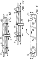
- FIG. 3 and 4 One embodiment of the armature assembly 18 is shown in Figures 3 and 4 to comprise a mounting plate 44 defining a central channel 46 which receives an armature plate 48 having an upper surface 50 confronting and intended to contact surface 40 of the electromagnet 20.
- the upper surface 50 of the armature plate 48 includes longitudinal grooves 52 dimensioned to engage projections 42 on the mounting portions 38 when power is applied to the electromagnet 20.
- the armature plate 48 is coupled to a separate backing plate 54. In the presence of a magnetic field generated by the electromagnet 20, the armature plate 48 moves with respect to the backing plate 54 between the two positions shown for example in Figures 4A and 4B.
- Figure 4A the armature plate 48 and backing plate 54 are both in a lower "unlocked" position.
- Figure 4B the armature plate 48 is in an elevated "locked" position while the backing plate 54 is in the same position shown in Figure 4A.
- a stud or similar element 56 is secured to the armature plate 48 and projects through an opening in the backing plate 54 and through another opening 58 in the mounting plate 44.
- the stud 56 includes an outwardly projecting flange 60 at a rearmost end of the stud.
- a coil spring 62 surrounds the stud with one end of the spring contacting the flange 60 and the other end of the spring contacting a back surface of the backing plate 54.
- the spring 62 acts as a biasing means for biasing the flange 60 away from backing plate 54 which has the effect of biasing the backing plate 54 and armature plate 48 toward each other.
- Figure 4A shows the position of the armature assembly when the door is "unlocked” while Figure 4B shows the relative position of the various elements of the armature assembly when power has been applied to the electromagnet and the door is "locked”.
- a pair of threaded studs 64 are provided which are adjustably engaged to the mounting plate 44.
- Each of the studs 64 includes an integral radial flange 66. Any outward adjustment of the studs 64 with respect to the frame 44 causes the flanges 66 to move out thereby displacing the armature plate 48 toward the electromagnet as shown in Figure 4C. Any outward adjustment of the rest position of the armature plate 48 by adjustment of the threaded studs 64 also causes the backing plate 54 to move outward since the backing plate 54 and armature plate 48 are biased toward each other by spring 62 as previously described.
- the armature plate 48 can be attracted to the electromagnet 20 against the gravitational force as well as the force provided by the biasing spring 62.
- the biasing force is set by the spring constant of spring 62 and is independent of the adjustment of the threaded studs where the distance of separation between the backing plate 54 and armature plate 48 are the same.
- the movement of the armature plate in response to an applied magnetic field is guided by means of openings 68 which surround the upper portion 70 of the threaded studs 64.
- the upper ends 71 of the studs 64 are substantially coplanar with the upper surface 50 of the armature plate 48 when the assembly is in the unlocked position shown in Figure 4A.
- the guiding function provided by the interaction between the openings 68 and the upper portions 70 operates over a range of movement equal to the thickness of the armature plate 48.
- the armature assembly 18 includes a channel shaped mounting plate 144 having a central channel 146 receiving armature plate 148 and backing plate 154.
- the biasing arrangement provided by studs 156, including flanges 160 and springs 162, is similar to that shown in Figures 3 and 4.
- Each end of the mounting plate 144 includes a slot 172 which receives a projecting tang portion 174 of armature plate 148.
- the sides 176 of the projecting tang 174 co-operate not only with the sides of the slots 172 but also with appropriate tabs for shoulders provided on a co-operating electromagnet such as that shown in U.S. patent 5,000,497.
- the position of the armature plate 148 relative to the mounting plate 144 is determined by threaded screws 178 which are fixed for rotation with respect to the plate 144 by means of E-Rings 180. Rotation of the threaded screws 178 causes a vertical displacement of the backing plate 154 between the positions shown in Figures 6B and 6C.
- a washer 182 surrounding each of the screws 178 made of neoprene or other similar material separates the backing plate 154 from the armature plate 148 and provides for effectively noiseless return of the armature plate 148 from the elevated position shown in Figure 6B to a lowered, rest position shown in Figure 6A upon cessation of the magnetic field in the adjacent electromagnet.
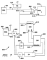
- a circuit 200 includes the door position sensor 26, a timing circuit means and a power circuit means.
- the timing circuit means consists of the one-shot timer 204, OR gate 206 and NOT gate 210.
- a voltage regulator 212 is electrically connected to supply a regulated voltage to the various elements of the circuit 200.
- the door position sensor 26 is connected by line 30 to one input of OR gate 206.
- Line 208 electrically connects the output of OR gate 206 to the RESET input 214 of one-shot timer 204 and the Q output 216 of the one-shot timer 204 is electrically connected to the input of NOT gate 210. Additionally, the Q output 216 is also connected to the ENABLE input 220 of oscillator 218 and to the relay 222 at terminal 224. The Q output 226 and the Q output 228 of oscillator 218 are electrically connected through driver 230 to charge pump 232. The charge pump 232 is electrically connected to capacitor 234 which serves as a charge storage means. Capacitor 234 is then connected to level detector 236 and is also connected to relay 222 at terminal 238. The output of level detector 236 is attached to the ENABLE input 240 of driver 230 and the output of relay 222 is attached to the locking coil 242 at terminal 244. Positive voltage of magnitude +V is applied to the locking coil 242 at terminal 246.
- the operation of the circuit 200 will now be described assuming that the lock is unpowered and the door 12 is open.
- the description of the normal operation of the circuit lies in three distinct areas: applying power to the lock, closing the door and then locking the lock.
- the oscillator 218 begins to oscillate, thus providing signals on the Q output 226 and Q output 228 to driver 230.
- Charge pump 232 is driven by the high current push-pull square wave output signals that operate out of phase with each other which are provided by the driver 230.
- the charge pump 232 is and functions as a voltage amplifier.
- the charge pump consists of an eight-stage capacitor and diode arrangement designed to multiply the input voltage to the charge pump 232 by approximately six to eight times.
- level detector 236 The action of the charge pump 232 charges the storage capacitor 234 to a maximum voltage determined by level detector 236.
- the level detector produces an output which, when applied to ENABLE input 240, disables driver 230.
- the inclusion of level detector 236 into the circuit only allows the storage capacitor 234 to charge to a safe, predetermined level corresponding to the threshold voltage level set by the level detector 236. When this level is achieved, level detector 236 disables the driver 230, thus removing the input power from the charge pump 232.
- the small magnet 28 located in the armature 18 comes into close proximity to the door position sensor 26.
- a signal is sent to OR gate 206.
- This signal is then applied to the RESET input 214 of timer 204 over line 208 which causes the timer 204 to reset and start a new field selectable timing sequence which provides a relocking delay for the lock to the end user.
- the Q output 216 of one-shot timer 204 goes high which accomplishes three different functions. First, a high level on the Q output 216 latches the RESET input 214 of one-shot timer 204 such that no further signals are accepted from door position sensor 26.
- Latching RESET input 214 is important because of the possibility that the door position sensor will sporadically respond to extraneous magnetic fields which would falsely reset the timer 204.
- the inclusion of NOT gate 210 and OR gate 206 comprises a latch which prevents any false stimulation of door position sensor 26.
- the second function of the Q output 216 of one-shot timer 204 going high is that when it is applied to the ENABLE input 220 of oscillator 218, it causes the oscillator to be disabled.
- Disabling the oscillator 218 precludes the application of the signals from the Q output 226 and the Q output 228 through driver 230 to the charge pump 232 which effectively removes any input power to the charge pump 232. This also reduces the input power required by the oscillator 218 since it is no longer in operation.
- the final and most important function of the Q output 216 of one-shot timer 204 going high is that it signals the relay 222 to close.
- the relay closes the accumulated charge in capacitor 234 is discharged across coil 242 at terminal 244 and a positive predetermined voltage of magnitude +V is additionally applied to the coil 242 at terminal 246 to provide the enhanced power necessary for a locked condition to be achieved.
- the positive voltage +V at terminal 246 will remain to keep the door in a locked condition.
- Circuit 200 is capable of operating correctly when the door is closed before power is applied to the lock through the external power source (not shown).
- the door position sensor immediately resets one-shot timer 204 which constitutes an immediate signal to the circuit to begin the relocking procedure.
- One-shot timer 204 has a minimum time delay that allows the charge pump 232 to fully charge the capacitor 234 before the capacitor is discharged to the locking coil 242 to provide the enhanced power necessary for a locked condition to be achieved.
Landscapes
- Physics & Mathematics (AREA)
- Electromagnetism (AREA)
- Engineering & Computer Science (AREA)
- Mechanical Engineering (AREA)
- Lock And Its Accessories (AREA)
Applications Claiming Priority (3)
| Application Number | Priority Date | Filing Date | Title |
|---|---|---|---|
| US07/812,713 US5184855A (en) | 1991-12-23 | 1991-12-23 | Electromagnetic door lock assembly |
| US812713 | 1991-12-23 | ||
| PCT/US1992/009310 WO1993013287A1 (en) | 1991-12-23 | 1992-10-30 | Electromagnetic door lock assembly |
Publications (2)
| Publication Number | Publication Date |
|---|---|
| EP0572586A1 EP0572586A1 (en) | 1993-12-08 |
| EP0572586B1 true EP0572586B1 (en) | 1995-11-29 |
Family
ID=25210411
Family Applications (1)
| Application Number | Title | Priority Date | Filing Date |
|---|---|---|---|
| EP19920923462 Expired - Lifetime EP0572586B1 (en) | 1991-12-23 | 1992-10-30 | Electromagnetic door lock assembly |
Country Status (8)
| Country | Link |
|---|---|
| US (1) | US5184855A (enExample) |
| EP (1) | EP0572586B1 (enExample) |
| AU (1) | AU658693B2 (enExample) |
| CA (1) | CA2101533C (enExample) |
| DE (1) | DE69206404T2 (enExample) |
| NZ (1) | NZ245103A (enExample) |
| TW (1) | TW230229B (enExample) |
| WO (1) | WO1993013287A1 (enExample) |
Families Citing this family (50)
| Publication number | Priority date | Publication date | Assignee | Title |
|---|---|---|---|---|
| GB9317051D0 (en) * | 1993-08-16 | 1993-09-29 | Burring Colin S | Driving devices |
| US5496079A (en) * | 1994-10-06 | 1996-03-05 | Harrow Products, Inc. | Swinging electromagnetic lock |
| US6359547B1 (en) * | 1994-11-15 | 2002-03-19 | William D. Denison | Electronic access control device |
| US6900720B2 (en) * | 2001-12-27 | 2005-05-31 | Micro Enhanced Technology, Inc. | Vending machines with field-programmable locks |
| US5641187A (en) * | 1995-09-11 | 1997-06-24 | Harrow Products, Inc. | Electromagnetic shear lock |
| US6609738B1 (en) * | 1996-02-20 | 2003-08-26 | Securitron Magnalock Corp. | Electromagnetic door lock system |
| US5897149A (en) * | 1996-04-17 | 1999-04-27 | Harrow Products, Inc. | Armature assembly for multiple locks |
| US6611414B1 (en) | 1996-08-30 | 2003-08-26 | Harrow Products, Inc. | Control system for electromagnetic lock |
| US6007119A (en) * | 1997-10-06 | 1999-12-28 | Securitron Magnalock Corp. | Multi-directional self-aligning shear type electromagnetic lock |
| US6053546A (en) * | 1998-06-03 | 2000-04-25 | Harrow Products, Inc. | Trigger system for electromagnetic lock |
| AUPQ023499A0 (en) * | 1999-05-07 | 1999-06-03 | Trimec Securities Pty. Ltd. | Improvements in delayed egress systems |
| FR2807089B1 (fr) * | 2000-03-30 | 2002-08-16 | Digit | Serrure electromagnetique |
| DE60110788D1 (de) * | 2000-06-29 | 2005-06-16 | Millard Paul | Türverriegelungsvorrichtung |
| US6454324B1 (en) * | 2000-08-25 | 2002-09-24 | John H. Lewis | Electronic door control and light |
| DE10050111C1 (de) * | 2000-10-09 | 2002-08-08 | Dorma Gmbh & Co Kg | Verriegelungsvorrichtung |
| ITBO20010343A1 (it) * | 2001-05-29 | 2002-11-29 | Angelantoni Ind Spa | Dispositivo a serratura magnetica con azionamento a trasponditore |
| US6902214B2 (en) * | 2001-06-19 | 2005-06-07 | Jerry R. Smith | Electromechanical locking method and device |
| US20050184857A1 (en) | 2003-12-11 | 2005-08-25 | Triteq Lock And Security, Llc | Electronic security apparatus and method for monitoring mechanical keys and other items |
| US20110276609A1 (en) | 2001-12-27 | 2011-11-10 | Denison William D | Method for Controlling and Recording the Security of an Enclosure |
| US7725897B2 (en) * | 2004-11-24 | 2010-05-25 | Kabushiki Kaisha Toshiba | Systems and methods for performing real-time processing using multiple processors |
| US6910373B2 (en) * | 2001-12-31 | 2005-06-28 | Life Measurement, Inc. | Apparatus and methods for repeatable door closure in a plethysmographic measurement chamber |
| DE10213722B4 (de) * | 2002-03-26 | 2007-05-03 | Eldomat Innovative Sicherheit Gmbh | Einrichtung zum Verschließen und Öffnen von schwenkbaren Türflügeln, die mittels Magnetkraft in Schließstellung gehalten werden |
| US20040195846A1 (en) * | 2003-04-04 | 2004-10-07 | Chang Chih Chung | Electromagnetic lock |
| US7000439B2 (en) * | 2003-08-18 | 2006-02-21 | Didomenico Dennis J | Appendage restraint system |
| US20050040665A1 (en) * | 2003-08-18 | 2005-02-24 | Didomenico Dennis J. | Powered restraint for securing person to vehicular exterior |
| DE10339363B4 (de) * | 2003-08-27 | 2011-02-03 | K.A. Schmersal Gmbh & Co | Zugangsschutzeinrichtung für einen Raumbereich |
| DE202004001958U1 (de) * | 2004-02-09 | 2005-06-30 | Drumm Gmbh | Magneto-mechanische Schließeinrichtung II |
| US20110254661A1 (en) | 2005-12-23 | 2011-10-20 | Invue Security Products Inc. | Programmable security system and method for protecting merchandise |
| US7522042B2 (en) * | 2006-05-18 | 2009-04-21 | T.K.M. Unlimited, Inc. | Door accessory power system |
| EP1862624B1 (de) * | 2006-06-01 | 2017-02-15 | Pilz Auslandsbeteiligungen GmbH | Zuhalteeinrichtung für eine Zugangsschutzvorrichtung |
| DK2049753T3 (en) * | 2006-07-20 | 2016-01-11 | Shanghai One Top Corp | MAGNETIC LOCK ORGAN WITH MECHANICAL LOCK OR RESISTANCE |
| CN101842237A (zh) * | 2007-09-10 | 2010-09-22 | 合荣电机工程有限公司 | 丝网印刷设备及其锁合装置 |
| US8820803B2 (en) * | 2009-03-02 | 2014-09-02 | Hanchett Entry Systems, Inc. | Electromagnetic lock having distance-sensing monitoring system |
| US9151096B2 (en) * | 2009-09-20 | 2015-10-06 | Hanchett Entry Systems, Inc. | Access control device for a door |
| DE102011009003A1 (de) * | 2011-01-14 | 2012-07-19 | Horatio Gmbh | Kupplung mit Permanentmagneten und elektrischer Magnetfeldkompensation |
| US20120205920A1 (en) * | 2011-02-11 | 2012-08-16 | Chandler Partners International, Ltd. | Autonomous door defense system and method |
| GB2489916B (en) * | 2011-04-04 | 2016-03-30 | Giovanni Maria Laporta | A device for enhancing closure of a window or door |
| WO2014161093A1 (en) * | 2013-04-05 | 2014-10-09 | Rutherford Controls Int'l Inc. | Low power magnetic lock assembly |
| US10290421B2 (en) * | 2014-01-23 | 2019-05-14 | Yi-Fan Liao | Manufacturing method of an attraction plate for electromagnetic door locks |
| USD739705S1 (en) * | 2014-09-17 | 2015-09-29 | Hampton Products International Corporation | Door-closing mechanism with a built-in light |
| US10127745B2 (en) | 2014-12-29 | 2018-11-13 | Invue Security Products Inc. | Merchandise display security systems and methods |
| CA2926835C (en) * | 2016-02-09 | 2024-05-14 | Hanchett Entry Systems, Inc. | Reduced power consumption electromagnetic lock |
| US20170298667A1 (en) * | 2016-04-14 | 2017-10-19 | Hanchett Entry Systems, Inc. | Door position sensor for an electromagnetic door lock |
| CA3021006A1 (en) | 2016-04-15 | 2017-10-19 | Mobile Tech, Inc. | Authorization control for an anti-theft security system |
| WO2017201190A1 (en) | 2016-05-18 | 2017-11-23 | Shanghai Yanfeng Jinqiao Automotive Trim Systems Co. Ltd | Console assembly for vehicle interior |
| US11572723B2 (en) | 2019-02-27 | 2023-02-07 | Shanghai Yanfeng Jinqiao Automotive Triim Systems Co. Ltd. | Vehicle interior component |
| US12241279B2 (en) * | 2021-06-18 | 2025-03-04 | Carrier Corporation | Systems and methods for control of a locking system |
| JP2024024838A (ja) * | 2022-08-10 | 2024-02-26 | 株式会社キーエンス | 安全スイッチ |
| JP2024024840A (ja) * | 2022-08-10 | 2024-02-26 | 株式会社キーエンス | 配線ユニット、シリアルカスケードコネクタシステム |
| JP2024024877A (ja) * | 2022-08-10 | 2024-02-26 | 株式会社キーエンス | 安全スイッチ |
Family Cites Families (14)
| Publication number | Priority date | Publication date | Assignee | Title |
|---|---|---|---|---|
| US3549955A (en) * | 1969-08-19 | 1970-12-22 | T O Paine | Drive circuit for minimizing power consumption in inductive load |
| US3629663A (en) * | 1970-04-17 | 1971-12-21 | N E M Controls Inc | Magnet controller |
| AU536558B2 (en) * | 1980-05-16 | 1984-05-10 | Tamao Morita | Engageable article |
| EP0045197A1 (en) * | 1980-07-28 | 1982-02-03 | Bsg (Security) Limited | Electromagnetic lock |
| GB2124044B (en) * | 1982-07-10 | 1986-03-05 | Lucas Ind Plc | Power supply circuit |
| US4593543A (en) * | 1983-10-05 | 1986-06-10 | Folger Adam Company | Security lock |
| US4682801A (en) * | 1984-08-31 | 1987-07-28 | Securitron-Magnalock Corp. | Electromagnet access control circuit |
| US4603370A (en) * | 1984-10-03 | 1986-07-29 | General Research Of Electronics, Inc. | Power-saving relay circuit |
| US4777556A (en) * | 1986-08-22 | 1988-10-11 | Datatrak | Solenoid activation circuitry using high voltage |
| US4716490A (en) * | 1987-04-03 | 1987-12-29 | George Alexanian | Power saving module |
| FR2621349B1 (fr) * | 1987-10-01 | 1994-03-04 | Mecalectro | Dispositif electromagnetique de maintien en position fermee d'un panneau ouvrant |
| US4981312A (en) * | 1988-06-29 | 1991-01-01 | Harrow Products, Inc. | Electromagnetic shear lock |
| US5016929A (en) * | 1989-06-13 | 1991-05-21 | Harrow Products, Inc. | Electromagnetic shear lock |
| US5065136A (en) * | 1990-11-19 | 1991-11-12 | Harrow Products, Inc. | Door security system |
-
1991
- 1991-12-23 US US07/812,713 patent/US5184855A/en not_active Expired - Lifetime
-
1992
- 1992-10-28 TW TW81108597A patent/TW230229B/zh active
- 1992-10-30 WO PCT/US1992/009310 patent/WO1993013287A1/en not_active Ceased
- 1992-10-30 CA CA 2101533 patent/CA2101533C/en not_active Expired - Fee Related
- 1992-10-30 DE DE69206404T patent/DE69206404T2/de not_active Expired - Fee Related
- 1992-10-30 AU AU29219/92A patent/AU658693B2/en not_active Ceased
- 1992-10-30 EP EP19920923462 patent/EP0572586B1/en not_active Expired - Lifetime
- 1992-11-12 NZ NZ245103A patent/NZ245103A/en not_active IP Right Cessation
Also Published As
| Publication number | Publication date |
|---|---|
| CA2101533A1 (en) | 1993-06-24 |
| AU2921992A (en) | 1993-07-28 |
| AU658693B2 (en) | 1995-04-27 |
| WO1993013287A1 (en) | 1993-07-08 |
| NZ245103A (en) | 1996-04-26 |
| EP0572586A1 (en) | 1993-12-08 |
| US5184855A (en) | 1993-02-09 |
| TW230229B (enExample) | 1994-09-11 |
| DE69206404D1 (de) | 1996-01-11 |
| CA2101533C (en) | 1999-03-23 |
| DE69206404T2 (de) | 1996-06-27 |
Similar Documents
| Publication | Publication Date | Title |
|---|---|---|
| EP0572586B1 (en) | Electromagnetic door lock assembly | |
| EP0852648B1 (en) | Improved electromagnetic shear lock | |
| US4439808A (en) | Electromagnetic lock | |
| US4656850A (en) | Electric lock | |
| US9797165B2 (en) | Electric latch retraction bar | |
| US4487439A (en) | Magnetic shear locking methods and apparatus | |
| US20210317691A1 (en) | Reduced power consumption electromagnetic lock | |
| US4845471A (en) | Door lock | |
| EP0654118B1 (en) | Electromagnetic door lock armature assembly | |
| US6104594A (en) | Electromagnetic latch retractor for exit bar | |
| US5184854A (en) | Electromagnetic lock | |
| WO1999063188A3 (en) | Trigger system for electromagnetic lock | |
| JP2002342852A (ja) | タグ装置 | |
| US20030205953A1 (en) | Electromagnetic locking system for cabinet doors and drawers | |
| EP3851619B1 (en) | Magnetic lock with resilient abutting member for eliminating remanence | |
| US20040189018A1 (en) | Push bar locking mechanism with rapid unlocking | |
| US6611414B1 (en) | Control system for electromagnetic lock | |
| CA1083206A (en) | Magnetically operated switch with cantilever mounted coil spring contact arm | |
| US4996525A (en) | R. F. lockout circuit for electronic locking system | |
| JPS6017912B2 (ja) | 錠装置 | |
| CN107100449B (zh) | 具有可移动的前板的制冷器具 | |
| WO2001031154A1 (en) | Magnetic lock | |
| US12068611B2 (en) | Energy-generating window and door latch assemblies and alarm system powered thereby | |
| GB2281096A (en) | Driving device | |
| WO2017158449A1 (en) | Automatic system for closing windows or doors |
Legal Events
| Date | Code | Title | Description |
|---|---|---|---|
| PUAI | Public reference made under article 153(3) epc to a published international application that has entered the european phase |
Free format text: ORIGINAL CODE: 0009012 |
|
| 17P | Request for examination filed |
Effective date: 19930917 |
|
| AK | Designated contracting states |
Kind code of ref document: A1 Designated state(s): DE FR GB IT |
|
| 17Q | First examination report despatched |
Effective date: 19940708 |
|
| GRAA | (expected) grant |
Free format text: ORIGINAL CODE: 0009210 |
|
| AK | Designated contracting states |
Kind code of ref document: B1 Designated state(s): DE FR GB IT |
|
| REF | Corresponds to: |
Ref document number: 69206404 Country of ref document: DE Date of ref document: 19960111 |
|
| ITF | It: translation for a ep patent filed | ||
| ET | Fr: translation filed | ||
| PLBE | No opposition filed within time limit |
Free format text: ORIGINAL CODE: 0009261 |
|
| STAA | Information on the status of an ep patent application or granted ep patent |
Free format text: STATUS: NO OPPOSITION FILED WITHIN TIME LIMIT |
|
| 26N | No opposition filed | ||
| REG | Reference to a national code |
Ref country code: GB Ref legal event code: IF02 |
|
| PGFP | Annual fee paid to national office [announced via postgrant information from national office to epo] |
Ref country code: FR Payment date: 20021002 Year of fee payment: 11 |
|
| PGFP | Annual fee paid to national office [announced via postgrant information from national office to epo] |
Ref country code: GB Payment date: 20021023 Year of fee payment: 11 |
|
| PGFP | Annual fee paid to national office [announced via postgrant information from national office to epo] |
Ref country code: DE Payment date: 20021031 Year of fee payment: 11 |
|
| PG25 | Lapsed in a contracting state [announced via postgrant information from national office to epo] |
Ref country code: GB Free format text: LAPSE BECAUSE OF NON-PAYMENT OF DUE FEES Effective date: 20031030 |
|
| PG25 | Lapsed in a contracting state [announced via postgrant information from national office to epo] |
Ref country code: DE Free format text: LAPSE BECAUSE OF NON-PAYMENT OF DUE FEES Effective date: 20040501 |
|
| GBPC | Gb: european patent ceased through non-payment of renewal fee |
Effective date: 20031030 |
|
| PG25 | Lapsed in a contracting state [announced via postgrant information from national office to epo] |
Ref country code: FR Free format text: LAPSE BECAUSE OF NON-PAYMENT OF DUE FEES Effective date: 20040630 |
|
| REG | Reference to a national code |
Ref country code: FR Ref legal event code: ST |
|
| PG25 | Lapsed in a contracting state [announced via postgrant information from national office to epo] |
Ref country code: IT Free format text: LAPSE BECAUSE OF NON-PAYMENT OF DUE FEES;WARNING: LAPSES OF ITALIAN PATENTS WITH EFFECTIVE DATE BEFORE 2007 MAY HAVE OCCURRED AT ANY TIME BEFORE 2007. THE CORRECT EFFECTIVE DATE MAY BE DIFFERENT FROM THE ONE RECORDED. Effective date: 20051030 |