EP0572427B1 - Current transformer - Google Patents
Current transformer Download PDFInfo
- Publication number
- EP0572427B1 EP0572427B1 EP92903057A EP92903057A EP0572427B1 EP 0572427 B1 EP0572427 B1 EP 0572427B1 EP 92903057 A EP92903057 A EP 92903057A EP 92903057 A EP92903057 A EP 92903057A EP 0572427 B1 EP0572427 B1 EP 0572427B1
- Authority
- EP
- European Patent Office
- Prior art keywords
- secondary winding
- winding
- current transformer
- capacitance
- conductor
- Prior art date
- Legal status (The legal status is an assumption and is not a legal conclusion. Google has not performed a legal analysis and makes no representation as to the accuracy of the status listed.)
- Expired - Lifetime
Links
Images
Classifications
-
- H—ELECTRICITY
- H01—ELECTRIC ELEMENTS
- H01F—MAGNETS; INDUCTANCES; TRANSFORMERS; SELECTION OF MATERIALS FOR THEIR MAGNETIC PROPERTIES
- H01F38/00—Adaptations of transformers or inductances for specific applications or functions
- H01F38/20—Instruments transformers
- H01F38/22—Instruments transformers for single phase ac
- H01F38/28—Current transformers
- H01F38/30—Constructions
- H01F2038/305—Constructions with toroidal magnetic core
-
- H—ELECTRICITY
- H02—GENERATION; CONVERSION OR DISTRIBUTION OF ELECTRIC POWER
- H02B—BOARDS, SUBSTATIONS OR SWITCHING ARRANGEMENTS FOR THE SUPPLY OR DISTRIBUTION OF ELECTRIC POWER
- H02B13/00—Arrangement of switchgear in which switches are enclosed in, or structurally associated with, a casing, e.g. cubicle
- H02B13/02—Arrangement of switchgear in which switches are enclosed in, or structurally associated with, a casing, e.g. cubicle with metal casing
- H02B13/035—Gas-insulated switchgear
- H02B13/0356—Mounting of monitoring devices, e.g. current transformers
Definitions
- the invention relates to a current transformer for installation in a metal encapsulation which is at ground potential and surrounds a high-voltage conductor and has a ring core and a secondary winding surrounding the ring core toroidally.
- Such a current transformer is known from EP-0 063 636 B1.
- the current transformer described there is overlapped by an inner tube which is electrically conductively connected to the encapsulation and a shielding body which is conductively connected to the encapsulation on the side of the ring core facing away from the inner tube and overlaps with the tube in an electrically insulated manner Secondary terminals protected.
- Such overvoltages can occur if the high-voltage conductor is exposed to rapid changes in current and voltage during connection and disconnection processes, for example within a switchgear assembly.
- Transversal electromagnetic traveling waves then run between the high-voltage conductor and the metal encapsulation in the longitudinal direction of the high-voltage conductor. Occurring traveling waves can continue practically unhindered without reflection via the relatively large capacitance formed by the overlap between the inner tube and the shielding body, without causing a significant increase in the potential of the secondary winding.
- the present invention has for its object to protect a current transformer of the type mentioned by means of structurally simple measures against overvoltages on the secondary winding due to switching operations.
- the object is achieved in that a further winding is applied to at least part of the toroidal core, which is conductively connected at one end to the ground potential.
- the electrical capacitance between the secondary winding and the grounded further winding is parallel to the stray capacitance between the secondary winding and the metal encapsulation lying at ground potential. This increases the total capacity of the secondary winding against the metal encapsulation.
- the capacitance between the high-voltage conductor and the secondary winding of the current transformer together with the capacitance of the secondary winding compared to the grounded metal encapsulation represents a capacitive voltage divider, the undervoltage capacitor of which is formed by the secondary winding and the metal encapsulation.
- the further winding can be designed so that it covers the entire ring core or at least essential parts of the ring core. In this case, however, the parts of the further winding which are furthest away from the earthed end are essentially connected to the earth potential with regard to high-frequency voltage changes via the self-inductance of the winding itself. In the case of high-frequency voltage changes, the proportion of the capacitance of these winding parts for the secondary winding, which are removed from the earthed end, only contributes to the total capacitance.
- Another advantageous embodiment of the invention provides that the further winding and the additional windings surround the secondary winding.
- This arrangement of the further winding and the additional windings provides shielding of the secondary winding from the electrical field surrounding the high-voltage conductor. As a result, the influences of the electrical field on the secondary winding can be kept particularly low.
- the invention is further advantageously designed in that the toroid is conductively connected to the earth potential at one point.
- the capacitance between the secondary winding and the toroid is connected in parallel with the capacitance between the secondary winding and the metal encapsulation. This leads to an increase in the total capacity between the secondary winding and the metal encapsulation.
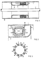
- Figure 1 shows schematically the metal encapsulation 1, in which a current transformer 2 is inserted, which surrounds a high-voltage conductor 3.
- the current transformer 2 consists of several toroidal cores 4, on which at least one secondary winding 5 is applied, which is connected to an electronic measuring arrangement, not shown, for measuring the current flowing in the high-voltage conductor 3.
- the secondary winding 5 is applied to the ring cores 4 in an insulated manner.
- the toroidal cores 4 are shielded from the high-voltage conductor 3 by an electrode 6.
- the electrode 6 is electrically conductively connected to the metal encapsulation 1 at one end 7.
- the other end 8 of the electrode 6 must not be conductively connected to the metal encapsulation 1, since otherwise a short-circuit conductor loop would be created around the ring cores 4, which would render the current transformer 2 unusable for measuring a current flowing in the high-voltage conductor 3.
- Rapid voltage and current increases which occur on the high-voltage conductor 3, run along the high-voltage conductor 3 between the latter and the metal encapsulation 1 as electromagnetic traveling waves. Such traveling waves also penetrate the space of the metal encapsulation 1 separated by the electrode 6, in which the ring cores 4 are located.
- such a traveling wave can generate an overvoltage in the secondary winding 5 of the current transformer 2, through which the measuring apparatus connected to the secondary winding 5 can be damaged.
- a further winding 9 and a plurality of additional windings 10 for shielding the secondary winding 5 are applied to each toroidal core 4 in addition to the secondary winding 5, as shown in FIG. 2.
- the further winding 9 and the additional windings 10 are each grounded at one end and insulated from one another and from the secondary winding 5 by insulating layers 12.
- a high electrical capacitance results between the secondary winding 5 and the other windings 9, 10. This capacitance is the stray capacitance between the secondary winding 5 and the metal encapsulation 1 electrically connected in parallel.
- the toroidal cores 4 themselves can each be connected at one point to the ground potential via an electrically conductive connection 11.
- the capacitance between the secondary winding 5 and each of the ring cores 4 is also connected in parallel with the stray capacitance between the secondary winding and the metal encapsulation 1.
- FIG. 3 shows a perspective view of a ring core 4 with a further winding 9 and additional windings 10, which are distributed on the circumference of the ring core 4.
- Each of the windings 9, 10 mentioned is connected at one end to the ground potential. The other end of the windings remains disconnected and is additionally insulated to avoid peak discharges.
- the secondary winding is not shown in FIG. 3 for reasons of simplification.
Abstract
Description
Die Erfindung bezieht sich auf einen Stromwandler zum Einbau in eine auf Erdpotential liegende, einen Hochspannungsleiter umgebende Metallkapselung mit einem Ringkern und einer den Ringkern toroidal umgebenden Sekundärwicklung.The invention relates to a current transformer for installation in a metal encapsulation which is at ground potential and surrounds a high-voltage conductor and has a ring core and a secondary winding surrounding the ring core toroidally.
Ein derartiger Stromwandler ist aus der EP-0 063 636 Bl bekannt. Der dort beschriebene Stromwandler wird durch ein am einen Ende mit der Kapselung elektrisch leitend verbundenes inneres Rohr und einen Abschirmkörper, der an der dem inneren Rohr abgekehrten Seite des Ringkerns mit der Kapselung leitend verbunden ist und mit dem Rohr elektrisch isoliert überlappt, vor Überspannungen an den Sekundärklemmen geschützt. Solche Überspannungen können auftreten, wenn der Hochspannungsleiter beispielsweise innerhalb einer Schaltanlage bei Zu- und Abschaltvorgängen schnellen Strom- und Spannungsänderungen ausgesetzt ist. Es laufen dann transversale elektromagnetische Wanderwellen zwischen dem Hochspannungsleiter und der Metallkapselung in Längsrichtung des Hochspannungsleiters. Auftretende Wanderwellen können über die zwischen dem inneren Rohr und dem Abschirmkörper durch die Überlappung gebildete, relativ große Kapazität praktisch ungehindert ohne Reflexion weiterlaufen, ohne eine wesentliche Potentialerhöhung der Sekundärwicklung hervorzurufen.Such a current transformer is known from EP-0 063 636 B1. The current transformer described there is overlapped by an inner tube which is electrically conductively connected to the encapsulation and a shielding body which is conductively connected to the encapsulation on the side of the ring core facing away from the inner tube and overlaps with the tube in an electrically insulated manner Secondary terminals protected. Such overvoltages can occur if the high-voltage conductor is exposed to rapid changes in current and voltage during connection and disconnection processes, for example within a switchgear assembly. Transversal electromagnetic traveling waves then run between the high-voltage conductor and the metal encapsulation in the longitudinal direction of the high-voltage conductor. Occurring traveling waves can continue practically unhindered without reflection via the relatively large capacitance formed by the overlap between the inner tube and the shielding body, without causing a significant increase in the potential of the secondary winding.
Der vorliegenden Erfindung liegt die Aufgabe zugrunde, einen Stromwandler der eingangs genannten Art mittels konstruktiv einfacher Maßnahmen vor Überspannungen an der Sekundärwicklung infolge von Schaltvorgängen zu schützen.The present invention has for its object to protect a current transformer of the type mentioned by means of structurally simple measures against overvoltages on the secondary winding due to switching operations.
Die Aufgabe wird erfindungsgemäß dadurch gelöst, daß auf wenigstens einen Teil des Ringkerns eine weitere Wicklung aufgebracht ist, die mit einem Ende mit dem Erdpotential leitend verbunden ist.The object is achieved in that a further winding is applied to at least part of the toroidal core, which is conductively connected at one end to the ground potential.
Die elektrische Kapazität zwischen der Sekundärwicklung und der geerdeten weiteren Wicklung liegt schaltungstechnisch parallel zu der Streukapazität zwischen der Sekundärwicklung und der auf Erdpotential liegenden Metallkapselung. Dadurch wird die Gesamtkapazität der Sekundärwicklung gegen die Metallkapselung vergrößert.In terms of circuitry, the electrical capacitance between the secondary winding and the grounded further winding is parallel to the stray capacitance between the secondary winding and the metal encapsulation lying at ground potential. This increases the total capacity of the secondary winding against the metal encapsulation.
Im allgemeinen stellt die Kapazität zwischen dem Hochspannungsleiter und der Sekundärwicklung des Stromwandlers zusammen mit der Kapazität der Sekundärwicklung gegenüber der geerdeten Metallkapselung einen kapazitiven Spannungsteiler dar, dessen Unterspannungskondensator durch die Sekundärwicklung und die Metallkapselung gebildet ist. Durch eine Vergrößerung der Kapazität dieses Unterspannungskondensators mittels der geerdeten weiteren Wicklung wird gemäß der Erfindung die Sekundärwicklung beim Auftreten von Wanderwellen an dem Hochspannungsleiter auf einem niedrigen Spannungsniveau gehalten. Dadurch wird auch bei an dem Hochspannungsleiter auftretenden schnellen Strom- und Spannungsänderungen eine Überspannung an der Sekundärwicklung vermieden.In general, the capacitance between the high-voltage conductor and the secondary winding of the current transformer together with the capacitance of the secondary winding compared to the grounded metal encapsulation represents a capacitive voltage divider, the undervoltage capacitor of which is formed by the secondary winding and the metal encapsulation. By increasing the capacitance of this undervoltage capacitor by means of the grounded additional winding, the secondary winding is kept at a low voltage level when traveling waves occur on the high-voltage conductor. As a result, an overvoltage on the secondary winding is avoided even in the event of rapid changes in current and voltage occurring on the high-voltage conductor.
Die weitere Wicklung kann so ausgebildet werden, daß sie den gesamten Ringkern oder wenigstens wesentliche Teile des Ringkerns überdeckt. In diesem Fall sind aber die Teile der weiteren Wicklung, die von dem geerdeten Ende am weitesten entfernt sind, im Hinblick auf hochfrequente Spannungsänderungen im wesentlichen über die Eigeninduktivität der Wicklung selbst mit dem Erdpotential verbunden. Bei hochfreqenten Spannungsänderungen trägt der Anteil der Kapazität dieser von dem geerdeten Ende entfernten Wicklungsteile zur Sekundärwicklung nur zum Teil zur Gesamtkapazität bei.The further winding can be designed so that it covers the entire ring core or at least essential parts of the ring core. In this case, however, the parts of the further winding which are furthest away from the earthed end are essentially connected to the earth potential with regard to high-frequency voltage changes via the self-inductance of the winding itself. In the case of high-frequency voltage changes, the proportion of the capacitance of these winding parts for the secondary winding, which are removed from the earthed end, only contributes to the total capacitance.
Es erweist sich in diesem Zusammenhang als vortelhaft, daß zusätzliche Wicklungen auf jeweils einem Teil des Ringkerns aufgebracht und mit jeweils einem Ende leitend mit dem Erdpotential verbunden sind.In this context, it has proven to be advantageous that additional windings are applied to each part of the toroidal core and are conductively connected at one end to the ground potential.
Dadurch, daß zusätzliche Wicklungen auf den Ringkern aufgebracht sind, ist die Kapazität zwischen der Sekundärwicklung und der auf Erdpotential liegenden Metallkapselung vergrößert. Somit werden die bei schnellen Spannungsänderungen auf dem Hochspannungsleiter auftretenden Spannungserhöhungen an der Sekundärwicklung gering gehalten. Das Aufbringen mehrerer zusätzlicher Wicklungen auf den Ringkern hat den Vorteil, daß jede der zusätzlichen Wicklungen mit dem Erdpotential auf direktem Wege leitend verbunden werden kann, wobei die direkte leitende Verbindung zum Erdpotential eine geringe Eigeninduktivität aufweist. Dadurch ist auch bei hohen Frequenzen eine wirksame Verbindung zwischen den zusätzlichen Wicklungen und dem Erdpotential gegeben.The fact that additional windings are applied to the toroidal core increases the capacitance between the secondary winding and the metal encapsulation lying at ground potential. Thus, the voltage increases on the secondary winding that occur during rapid voltage changes on the high-voltage conductor are kept low. The application of several additional windings to the toroid has the advantage that each of the additional windings can be conductively connected to the earth potential in a direct way, the direct conductive connection to the earth potential having a low self-inductance. This provides an effective connection between the additional windings and the earth potential even at high frequencies.
Eine weitere vorteilhafte Ausgestaltung der Erfindung sieht vor, daß die weitere Wicklung und die zusätzlichen Wicklungen die Sekundärwicklung umgeben.Another advantageous embodiment of the invention provides that the further winding and the additional windings surround the secondary winding.
Durch diese Anordnung der weiteren Wicklung und der zusätzlichen Wicklungen ist eine Abschirmung der Sekundärwicklung von dem den Hochspannungsleiter umgebenden elektrischen Feld gegeben. Dadurch können die Einflüsse des elektrischen Feldes auf die Sekundärwicklung besonders gering gehalten werden.This arrangement of the further winding and the additional windings provides shielding of the secondary winding from the electrical field surrounding the high-voltage conductor. As a result, the influences of the electrical field on the secondary winding can be kept particularly low.
Die Erfindung wird weiterhin dadurch vorteilhaft ausgestaltet, daß der Ringkern an einer Stelle mit dem Erdpotential leitend verbunden ist.The invention is further advantageously designed in that the toroid is conductively connected to the earth potential at one point.
Dadurch wird die Kapazität zwischen der Sekundärwicklung und dem Ringkern schaltungstechnisch zu der Kapazität zwischen der Sekundärwicklung und der Metallkapselung parallelgeschaltet. Dies führt zu einer Erhöhung der Gesamtkapazität zwischen der Sekundärwicklung und der Metallkapselung.As a result, the capacitance between the secondary winding and the toroid is connected in parallel with the capacitance between the secondary winding and the metal encapsulation. This leads to an increase in the total capacity between the secondary winding and the metal encapsulation.
Im folgenden wird die Erfindung anhand eines Ausführungsbeispiels in einer Zeichnung gezeigt und anschließend beschrieben.In the following, the invention is shown on the basis of an exemplary embodiment in a drawing and then described.
Dabei zeigt
Figur 1- eine Metallkapselung mit einem Stromwandler und einem Hochspannungsleiter schematisch im Längsschnitt,
Figur 2- einen Halbschnitt durch den Stromwandler mit einer schematischen Darstellung der Sekundärwicklung und der weiteren Wicklung,
Figur 3- den Ringkern eines erfindungsgemäßen Stromwandlers mit mehreren zusätzlichen Windungen.
- Figure 1
- a metal encapsulation with a current transformer and a high voltage conductor schematically in longitudinal section,
- Figure 2
- a half section through the current transformer with a schematic representation of the secondary winding and the further winding,
- Figure 3
- the toroidal core of a current transformer according to the invention with several additional turns.
Figur 1 zeigt schematisch die Metallkapselung 1, in die ein Stromwandler 2 eingesetzt ist, der einen Hochspannungsleiter 3 umgibt. Der Stromwandler 2 besteht aus mehreren Ringkernen 4, auf denen wenigstens eine Sekundärwicklung 5 aufgebracht ist, die zur Messung des in dem Hochspannungsleiter 3 fließenden Stromes mit einer nicht dargestellten elektronischen Meßanordnung verbunden ist. Die Sekundärwicklung 5 ist auf die Ringkerne 4 jeweils isoliert aufgebracht.Figure 1 shows schematically the
Die Ringkerne 4 sind gegenüber dem Hochspannungsleiter 3 durch eine Elektrode 6 abgeschirmt. Die Elektrode 6 ist an einem Ende 7 mit der Metallkapselung 1 elektrisch leitend verbunden. Das andere Ende 8 der Elektrode 6 darf mit der Metallkapselung 1 nicht leitend verbunden werden, da sonst eine Kurzschlußleiterschleife um die Ringkerne 4 herum geschaffen würde, die den Stromwandler 2 zur Messung eines in dem Hochspannungsleiter 3 fließenden Stromes unbrauchbar machen würde.The
Schnelle Spannungs- und Stromerhöhungen, die an dem Hochspannungsleiter 3 auftreten, laufen entlang des Hochspannungsleiters 3 zwischen diesem und der Metallkapselung 1 als elektromagnetische Wanderwellen. Solche Wanderwellen durchsetzen auch den durch die Elektrode 6 abgetrennten Raum der Metallkapselung 1, in dem sich die Ringkerne 4 befinden.Rapid voltage and current increases, which occur on the high-
Im allgemeinen kann eine solche Wanderwelle in der Sekundärwicklung 5 des Stromwandlers 2 eine Überspannung erzeugen, durch die die an die Sekundärwicklung 5 angeschlossene Meßapparatur beschädigt werden kann. Zur Verhinderung des Auftretens solcher Überspannungen sind gemäß der Erfindung auf jeden Ringkern 4 zusätzlich zu der Sekundärwicklung 5 eine weitere Wicklung 9 und mehrere zusätzliche Wicklungen 10 zur Abschirmung der Sekundärwicklung 5 aufgebracht, wie Figur 2 zeigt. Die weitere Wicklung 9 und die zusätzlichen Wicklungen 10 sind jeweils an einem Ende geerdet und gegeneinander sowie gegen die Sekundärwicklung 5 durch isolierende Schichten 12 isoliert. Zwischen der Sekundärwicklung 5 und den übrigen Wicklungen 9, 10 ergibt sich eine hohe elektrische Kapazität. Diese Kapazität ist der Streukapazität zwischen der Sekundärwicklung 5 und der Metallkapselung 1 elektrisch parallelgeschaltet.In general, such a traveling wave can generate an overvoltage in the secondary winding 5 of the
Zusätzlich können noch die Ringkerne 4 selbst jeweils an einer Stelle über eine elektrisch leitende Verbindung 11 mit dem Erdpotential verbunden sein. Dadurch wird auch die Kapazität zwischen der Sekundärwicklung 5 und jedem der Ringkerne 4 zu der Streukapazität zwischen der Sekundärwicklung und der Metallkapselung 1 parallelgeschaltet.In addition, the
Figur 3 zeigt in einer perspektivischen Ansicht einen Ringkern 4 mit einer weiteren Wicklung 9 und zusätzlichen Wicklungen 10, die am Umfang des Ringkernes 4 verteilt sind. Jede der genannten Wicklungen 9, 10 ist an einem Ende mit dem Erdpotential verbunden. Das andere Ende der Wicklungen bleibt jeweils unverbunden und ist zur Vermeidung von Spitzenentladungen zusätzlich isoliert. Die Sekundärwicklung ist in der Figur 3 aus Vereinfachungsgründen nicht dargestellt.FIG. 3 shows a perspective view of a
Claims (4)
- A current transformer for installation into a metal enclosure, which lies on earth potential, and which surrounds a high voltage conductor, said current conductor having an annular core and a secondary winding, which toroidally surrounds the annular core, characterized in that on at least one part of the annular core (4), a further winding (9) is mounted, which is conductively connected with one end, with the earth potential.
- A current transformer according to claim 1, characterized in that additional windings (10) are each mounted on one part of the annular core (4) and are each conductively connected with one end, with the earth potential.
- A current transformer according to claim 1 or 2, characterized in that the further winding (9) and the additional windings (10), surround the secondary winding (5).
- A current transformer according to claim 1 or one of the preceding claims, characterized in that the annular core (4) is conductively connected at one place, with the earth potential.
Applications Claiming Priority (3)
| Application Number | Priority Date | Filing Date | Title |
|---|---|---|---|
| DE4106034A DE4106034A1 (en) | 1991-02-22 | 1991-02-22 | POWER CONVERTER |
| DE4106034 | 1991-02-22 | ||
| PCT/DE1992/000051 WO1992015104A1 (en) | 1991-02-22 | 1992-01-24 | Current transformer |
Publications (2)
| Publication Number | Publication Date |
|---|---|
| EP0572427A1 EP0572427A1 (en) | 1993-12-08 |
| EP0572427B1 true EP0572427B1 (en) | 1994-11-23 |
Family
ID=6425930
Family Applications (1)
| Application Number | Title | Priority Date | Filing Date |
|---|---|---|---|
| EP92903057A Expired - Lifetime EP0572427B1 (en) | 1991-02-22 | 1992-01-24 | Current transformer |
Country Status (6)
| Country | Link |
|---|---|
| EP (1) | EP0572427B1 (en) |
| JP (1) | JPH06505125A (en) |
| AT (1) | ATE114384T1 (en) |
| CA (1) | CA2104585A1 (en) |
| DE (2) | DE4106034A1 (en) |
| WO (1) | WO1992015104A1 (en) |
Families Citing this family (4)
| Publication number | Priority date | Publication date | Assignee | Title |
|---|---|---|---|---|
| DE4229680A1 (en) * | 1992-09-02 | 1994-03-03 | Siemens Ag | Power converter |
| DE9217807U1 (en) * | 1992-12-24 | 1993-04-08 | Kommanditgesellschaft Ritz Messwandler Gmbh & Co, 2000 Hamburg, De | |
| EP0668598B1 (en) | 1994-02-17 | 1997-04-02 | Gec Alsthom T&D Ag | Current transformer with annular core to be built in a metal cast high-tension switchgear installation |
| DE102005007334B4 (en) * | 2005-02-17 | 2007-02-08 | Siemens Ag | Summation current transformer for the universal current-sensitive detection of an electrical differential current |
Family Cites Families (3)
| Publication number | Priority date | Publication date | Assignee | Title |
|---|---|---|---|---|
| DE683018C (en) * | 1936-08-21 | 1939-10-27 | Stalturbine G M B H | Single-wire current transformer with two-part bushing insulator |
| DE2325441C2 (en) * | 1973-05-17 | 1989-07-20 | Siemens AG, 1000 Berlin und 8000 München | Measuring transducer for installation in a metal capsule of a switchgear system |
| EP0063636B2 (en) * | 1981-04-28 | 1992-12-30 | Sprecher + Schuh AG | Current transformer with annular case to be built in a metal cast high-tension switchgear installation |
-
1991
- 1991-02-22 DE DE4106034A patent/DE4106034A1/en not_active Withdrawn
-
1992
- 1992-01-24 JP JP4503013A patent/JPH06505125A/en active Pending
- 1992-01-24 CA CA002104585A patent/CA2104585A1/en not_active Abandoned
- 1992-01-24 AT AT92903057T patent/ATE114384T1/en not_active IP Right Cessation
- 1992-01-24 EP EP92903057A patent/EP0572427B1/en not_active Expired - Lifetime
- 1992-01-24 WO PCT/DE1992/000051 patent/WO1992015104A1/en active IP Right Grant
- 1992-01-24 DE DE59200812T patent/DE59200812D1/en not_active Expired - Fee Related
Also Published As
| Publication number | Publication date |
|---|---|
| JPH06505125A (en) | 1994-06-09 |
| DE4106034A1 (en) | 1992-08-27 |
| CA2104585A1 (en) | 1992-08-23 |
| WO1992015104A1 (en) | 1992-09-03 |
| ATE114384T1 (en) | 1994-12-15 |
| EP0572427A1 (en) | 1993-12-08 |
| DE59200812D1 (en) | 1995-01-05 |
Similar Documents
| Publication | Publication Date | Title |
|---|---|---|
| EP1864304B1 (en) | Transformer provided with an electrical shielding | |
| EP1516390B1 (en) | Interference filter and lightning conductor device | |
| EP1329005B1 (en) | Surge protection filter and lightning conductor system | |
| DE3109766A1 (en) | Apparatus plug socket | |
| CH675933A5 (en) | Triaxial electromagnetic pulse conductor - has inner conductor and two screening conductors with unit to maintain contact with overload conductor | |
| EP0497169A2 (en) | X-ray line | |
| EP0572427B1 (en) | Current transformer | |
| DE3929402A1 (en) | X-RAY DEVICE | |
| DE2530892C3 (en) | Particle accelerator for charged particles | |
| DE3027469A1 (en) | Mobile communications centre lighting protection - has transport vehicle parts to be earthed and excess voltage conductors earthing electrodes connected to plates on ground | |
| EP0768684B1 (en) | Current transformer with annular core to be built in a metal cast high-tension switchgear installation | |
| CH660261A5 (en) | EMP suppressor in a coaxial conductor | |
| DE4107459C2 (en) | Device for overvoltage protection of an electrical terminal connected to a cable | |
| DE571127C (en) | Circuit arrangement for eliminating radio interference | |
| DE4311125B4 (en) | EMC filters for systems, systems and shielded rooms | |
| EP0658271B1 (en) | Current transformer | |
| DE3029778C2 (en) | Measuring arrangement for recording the conductor voltage in a metal-enclosed, compressed gas-insulated high-voltage switchgear | |
| DE498440C (en) | Overvoltage protection device | |
| EP0665561B1 (en) | Current transformer with annular core to be built in a metal cast high-tension switchgear installation | |
| DE547398C (en) | Line system for the high-voltage side of electrical ignition systems | |
| DE623417C (en) | ||
| DE1640612A1 (en) | Arrangement for the protection of the telecommunication cables against inductive influences of high voltage systems | |
| DE3141533C2 (en) | ||
| DE724115C (en) | Overvoltage protection for multi-phase windings of electrical equipment connected to an isolated neutral point | |
| DE1224988B (en) | Device for radio interference suppression of ignition systems of internal combustion engines |
Legal Events
| Date | Code | Title | Description |
|---|---|---|---|
| PUAI | Public reference made under article 153(3) epc to a published international application that has entered the european phase |
Free format text: ORIGINAL CODE: 0009012 |
|
| 17P | Request for examination filed |
Effective date: 19930519 |
|
| AK | Designated contracting states |
Kind code of ref document: A1 Designated state(s): AT BE CH DE FR GB IT LI NL SE |
|
| 17Q | First examination report despatched |
Effective date: 19940209 |
|
| GRAA | (expected) grant |
Free format text: ORIGINAL CODE: 0009210 |
|
| AK | Designated contracting states |
Kind code of ref document: B1 Designated state(s): AT BE CH DE FR GB IT LI NL SE |
|
| REF | Corresponds to: |
Ref document number: 114384 Country of ref document: AT Date of ref document: 19941215 Kind code of ref document: T |
|
| REF | Corresponds to: |
Ref document number: 59200812 Country of ref document: DE Date of ref document: 19950105 |
|
| PGFP | Annual fee paid to national office [announced via postgrant information from national office to epo] |
Ref country code: NL Payment date: 19950131 Year of fee payment: 4 |
|
| ITF | It: translation for a ep patent filed |
Owner name: STUDIO JAUMANN |
|
| GBT | Gb: translation of ep patent filed (gb section 77(6)(a)/1977) |
Effective date: 19950201 |
|
| ET | Fr: translation filed | ||
| REG | Reference to a national code |
Ref country code: CH Ref legal event code: PUE Owner name: HAEFELY TRENCH MWB GMBH |
|
| REG | Reference to a national code |
Ref country code: FR Ref legal event code: TP |
|
| PLBE | No opposition filed within time limit |
Free format text: ORIGINAL CODE: 0009261 |
|
| STAA | Information on the status of an ep patent application or granted ep patent |
Free format text: STATUS: NO OPPOSITION FILED WITHIN TIME LIMIT |
|
| 26N | No opposition filed | ||
| PG25 | Lapsed in a contracting state [announced via postgrant information from national office to epo] |
Ref country code: GB Effective date: 19960124 |
|
| PG25 | Lapsed in a contracting state [announced via postgrant information from national office to epo] |
Ref country code: NL Effective date: 19960801 |
|
| GBPC | Gb: european patent ceased through non-payment of renewal fee |
Effective date: 19960124 |
|
| NLV4 | Nl: lapsed or anulled due to non-payment of the annual fee |
Effective date: 19960801 |
|
| PGFP | Annual fee paid to national office [announced via postgrant information from national office to epo] |
Ref country code: AT Payment date: 20061211 Year of fee payment: 16 |
|
| PGFP | Annual fee paid to national office [announced via postgrant information from national office to epo] |
Ref country code: SE Payment date: 20070111 Year of fee payment: 16 |
|
| PGFP | Annual fee paid to national office [announced via postgrant information from national office to epo] |
Ref country code: BE Payment date: 20070125 Year of fee payment: 16 |
|
| PGFP | Annual fee paid to national office [announced via postgrant information from national office to epo] |
Ref country code: DE Payment date: 20070322 Year of fee payment: 16 |
|
| PGFP | Annual fee paid to national office [announced via postgrant information from national office to epo] |
Ref country code: CH Payment date: 20070403 Year of fee payment: 16 |
|
| REG | Reference to a national code |
Ref country code: CH Ref legal event code: PFA Owner name: HAEFELY TRENCH MWB GMBH Free format text: HAEFELY TRENCH MWB GMBH#NUERNBERGERSTRASSE 199#D-96050 BAMBERG (DE) -TRANSFER TO- HAEFELY TRENCH MWB GMBH#NUERNBERGERSTRASSE 199#D-96050 BAMBERG (DE) |
|
| PGFP | Annual fee paid to national office [announced via postgrant information from national office to epo] |
Ref country code: IT Payment date: 20070517 Year of fee payment: 16 |
|
| PGFP | Annual fee paid to national office [announced via postgrant information from national office to epo] |
Ref country code: FR Payment date: 20070123 Year of fee payment: 16 |
|
| BERE | Be: lapsed |
Owner name: SIEMENS A.G. Effective date: 20080131 |
|
| REG | Reference to a national code |
Ref country code: CH Ref legal event code: PL |
|
| EUG | Se: european patent has lapsed | ||
| PG25 | Lapsed in a contracting state [announced via postgrant information from national office to epo] |
Ref country code: LI Free format text: LAPSE BECAUSE OF NON-PAYMENT OF DUE FEES Effective date: 20080131 Ref country code: DE Free format text: LAPSE BECAUSE OF NON-PAYMENT OF DUE FEES Effective date: 20080801 Ref country code: CH Free format text: LAPSE BECAUSE OF NON-PAYMENT OF DUE FEES Effective date: 20080131 |
|
| PG25 | Lapsed in a contracting state [announced via postgrant information from national office to epo] |
Ref country code: AT Free format text: LAPSE BECAUSE OF NON-PAYMENT OF DUE FEES Effective date: 20080124 |
|
| REG | Reference to a national code |
Ref country code: FR Ref legal event code: ST Effective date: 20081029 |
|
| PG25 | Lapsed in a contracting state [announced via postgrant information from national office to epo] |
Ref country code: SE Free format text: LAPSE BECAUSE OF NON-PAYMENT OF DUE FEES Effective date: 20080125 |
|
| PG25 | Lapsed in a contracting state [announced via postgrant information from national office to epo] |
Ref country code: BE Free format text: LAPSE BECAUSE OF NON-PAYMENT OF DUE FEES Effective date: 20080131 |
|
| PG25 | Lapsed in a contracting state [announced via postgrant information from national office to epo] |
Ref country code: FR Free format text: LAPSE BECAUSE OF NON-PAYMENT OF DUE FEES Effective date: 20080131 |
|
| PG25 | Lapsed in a contracting state [announced via postgrant information from national office to epo] |
Ref country code: IT Free format text: LAPSE BECAUSE OF NON-PAYMENT OF DUE FEES Effective date: 20080124 |