EP0572379B1 - Methode pour la transmission sans contact d'informations - Google Patents
Methode pour la transmission sans contact d'informations Download PDFInfo
- Publication number
- EP0572379B1 EP0572379B1 EP90912698A EP90912698A EP0572379B1 EP 0572379 B1 EP0572379 B1 EP 0572379B1 EP 90912698 A EP90912698 A EP 90912698A EP 90912698 A EP90912698 A EP 90912698A EP 0572379 B1 EP0572379 B1 EP 0572379B1
- Authority
- EP
- European Patent Office
- Prior art keywords
- frequency
- transmitter
- carrier wave
- sidebands
- transponder
- Prior art date
- Legal status (The legal status is an assumption and is not a legal conclusion. Google has not performed a legal analysis and makes no representation as to the accuracy of the status listed.)
- Expired - Lifetime
Links
Images
Classifications
-
- G—PHYSICS
- G01—MEASURING; TESTING
- G01S—RADIO DIRECTION-FINDING; RADIO NAVIGATION; DETERMINING DISTANCE OR VELOCITY BY USE OF RADIO WAVES; LOCATING OR PRESENCE-DETECTING BY USE OF THE REFLECTION OR RERADIATION OF RADIO WAVES; ANALOGOUS ARRANGEMENTS USING OTHER WAVES
- G01S13/00—Systems using the reflection or reradiation of radio waves, e.g. radar systems; Analogous systems using reflection or reradiation of waves whose nature or wavelength is irrelevant or unspecified
- G01S13/74—Systems using reradiation of radio waves, e.g. secondary radar systems; Analogous systems
- G01S13/82—Systems using reradiation of radio waves, e.g. secondary radar systems; Analogous systems wherein continuous-type signals are transmitted
- G01S13/825—Systems using reradiation of radio waves, e.g. secondary radar systems; Analogous systems wherein continuous-type signals are transmitted with exchange of information between interrogator and responder
-
- G—PHYSICS
- G06—COMPUTING OR CALCULATING; COUNTING
- G06K—GRAPHICAL DATA READING; PRESENTATION OF DATA; RECORD CARRIERS; HANDLING RECORD CARRIERS
- G06K7/00—Methods or arrangements for sensing record carriers, e.g. for reading patterns
- G06K7/10—Methods or arrangements for sensing record carriers, e.g. for reading patterns by electromagnetic radiation, e.g. optical sensing; by corpuscular radiation
- G06K7/10009—Methods or arrangements for sensing record carriers, e.g. for reading patterns by electromagnetic radiation, e.g. optical sensing; by corpuscular radiation sensing by radiation using wavelengths larger than 0.1 mm, e.g. radio-waves or microwaves
Definitions
- the present invention relates to a method for the contactless transmission of information.
- the Swedish Patent Specification No. SE-B-459775 published on 31/7/89 (Swedish Patent Application 8802230-6), also published as EP-A-0378639 on 25/7/90, describes apparatus for the contactless transmission of information over a serial twin-cable data bus, comprising a clock line and a data line connected to a transmitter, a receiver and a demodulator.
- the transmitter includes an oscillator and a modulator which is intended to modulate the signal generated by the oscillator in response to the clock line signals and data line signals respectively.
- the invention defined in said Patent Specification is characterized in that the modulator is constructed to carry out on the signal generated by the oscillator two significantly separated modulation steps which do not coincide in time, therewith to form two mutually independent signal channels, of which a first is intended for data signals and the other is intended for the clock signals.
- the demodulator is constructed to demodulate signals which are received by the receiver and which have been modulated in the aforesaid manner and also to recreate said two signals.
- the demodulator has a clock-line output and a data-line output.
- the Patent Specification defines a method of separating data and clock lines, by using pauses in transmission as information carriers, wherewith, e.g., switching or marking of levels in the clock line triggers a first modulation step, which constitutes a short transmission pause, whereas switching or marking of levels in the data line triggers a second modulation step which constitutes two rapid, sequential transmission pauses.
- the present invention provides a novel and useful method for application in such data buses or other data links, such as to enable the signals transmitted from the master side to be used as control oscillators on the slave side, and therewith to enable the slave side to transmit signals which are received on the master side without the signals transmitted from said master side disturbing the reception of the signals transmitted from the slave side and without the occurrence of zero settings, or so-called nodes, in the signal from the slave side.
- the present invention thus relates to a method for the contactless transmission of information between a transmitter/receiver unit and a transponder, the transmitter/receiver unit comprising oscillators, transmitter and receiver antennas, a modulator and a detection circuit, and the transponder including a transmitter/receiver antenna, a modulator and a detection circuit.
- the invention is characterized in that the transmitter/receiver unit is caused to transmit a first and a second carrier wave which have mutually different frequencies (f1, f2) but mutually the same phase; in that the difference frequency is formed in the transponder; in that a third signal having the difference frequency (f3) is caused to be divided to a fourth signal having half the difference frequency (f4); in that the fourth signal is caused to modulate the two carrier waves received in the transponder by being applied to a diode or like device, such that the received carrier waves are reflected back to the transmitter/receiver unit; in that the signal received in the transmitter/receiver unit is mixed down with one of the first or the second carrier wave frequencies; and in that each of the two sidebands on respective sides of the carrier wave frequency with which said mixing is effected are brought forward, said sidebands differing from the last mentioned carrier wave frequency by a frequency which is equal to half the difference frequency (f4), wherein that sideband of said sidebands which has a frequency that lies between the carrier wave
- the link or the bus operate at microwave frequencies, although the invention is not restricted to these frequency bands, but can be applied at other frequency bands.
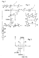
- FIGS 1 and 2 illustrate schematically a transmitter/receiver unit 1, hereinafter called the transmitter, and a transponder 2. These units 1, 2 form a link by means of which information, e.g. data, can be transmitted in both directions.
- the transmitter 1 includes, among other things, oscillators 3, 4, transmitter and receiver antennas 5, 6, 7, a modulator 8, and a detection circuit 9.
- the transponder 2 includes, among other things, a transmitter/receiver antenna 10, a modulator 11, 12 and a detection circuit 13.
- the transmitter 1 also includes mixers 14-16, bandpass filters 17, 25, amplifiers 18, 19, a rectifier 20 and a summation circuit 21.
- the transponder 2 further includes a circuit 22 which is intended to form the difference frequency between two frequencies, and a frequency divider 23.
- the transponder may also include a memory store 24, which may be constructed to deliver information and also to receive information and to store the information received.
- the transmitter is caused to transmit a first and a second carrier wave of mutually different frequencies (f1, f2).
- f1, f2 This is illustrated in Figure 1, in that the oscillator 3 is shown to generate a signal having a frequency of 2450 MHz, which is sent to the antenna 6.
- the signal is also sent to a mixer 15, to which there is also applied a signal from a further oscillator 4, which in the illustrated case generates the frequency 13.5 MHz.
- the mixer 15 is constructed so that a signal having the frequency 2463.5 MHz will appear on its output when the oscillator 4 is activated by the modulator 8.
- This signal is sent along the lines 30-31 to the antenna 6.
- a first and a second signal in the form of two carrier waves are transmitted by means of the antenna 6.
- the transponder includes a circuit 22 which is intended to form the difference frequency between the two carrier wave frequencies.
- the transponder 2 there is formed in the transponder 2 a third signal which has the difference frequency formed in the circuit 22.
- the frequency divider 23 in the transponder is operative to divide the third signal having the difference frequency (f3) into a fourth signal of half the difference frequency (f4).
- the fourth signal is caused to modulate the two carrier waves received in the transponder, by being applied to a diode or like device in the modulator 12, so that the received carrier waves will be reflected back to the transmitter 1, without supplying further energy to the carrier waves.
- the modulator in the transponder also includes a circuit 11 which is operative to start and stop the modulation step in accordance with the information to be transmitted from the transponder 2 to the receiver 1.
- This information can be delivered to the circuit 11 from a memory store 24, or alternatively from a data line 32.
- the two carrier waves are transmitted from the transponder, each modulated with a frequency f4 which is equal to half the difference frequency between the carrier wave frequencies.
- the signal received on the antenna 7 of the transmitter 1 is mixed with the frequency of the first or the second carrier waves in a mixer 14 intended therefor.
- the two sidebands on respective sides of the carrier wave frequency with which said mixing is effected are brought forward in this way. These two sidebands differ from the last mentioned carrier wave frequency by a frequency which is equal to half the difference frequency (f4).
- Figure 3 illustrates a frequency diagram in which the transmitted carrier waves have been designated f1 and f2 respectively. If mixing-down in the modulator 14 is effected with the frequency 2450 MHz, the sidebands whose frequencies differ from 2450 MHz by 6.75 MHz will therefore lie downstream of the mixer 14.
- the other carrier wave in the transponder is also modulated, and consequently this carrier wave with associated pair of corresponding sidebands will be received in the receiver.
- One of these last mentioned sidebands has a frequency which is 6.75 MHz higher than the frequency of the other carrier wave, which carrier wave has a frequency of 2463.5 MHz, and the other of said sidebands has a frequency which is 6.75 MHz lower than 2463.5 MHz.
- the combined sideband is given an amplitude which differs from the amplitude of the other, filtered sideband, as illustrated in Figure 3.
- the combined sideband and said other sideband are filtered-out with the aid of the bandpass filter 17.
- Two methods and combinations therebetween can be employed to ensure that the combined sideband will have an amplitude which differs from the other sideband.
- One method is to permit the carrier waves to have a sufficiently large amplitude difference, for example a difference factor of at least about 2.
- Another method is to permit the carrier waves to have the same amplitude but to cause the signal which modulates the carrier waves in the transponder to have a phase which is different to the phase of that signal which is frequency-halved and mixed-down in the transponder, i.e. the aforesaid fourth signal.
- both amplitudes and phases can be varied, wherewith the amplitude difference between the carrier waves need no longer be of the order of twice the difference.
- the three sidebands namely the two sidebands which form the combined sideband and said other sideband, do not have vectors in an amplitude-phase diagram which give resultants which are equal to zero subsequent to mixing in the transmitter/receiver unit.
- the central sideband has an amplitude which is different to the other sideband of the sideband pair results in that no zero positions, or nodes, can occur in the received signal as a result of interference or disturbance.
- the filtered sideband, or pair of sidebands, is detected in the detection circuit 9 of the transmitter with respect to the information content of the sidebands.
- the circuit 20 is a rectifier.
- the signal appearing on the output of the rectifier 20 is therefore a data signal.
- the clock frequency in the transmitter is 13.5 MHz, and the clock signal can be taken from the oscillator 4, through an output.
- the clock signal in the transponder 2 also has a frequency of 13.5 MHz and is taken from the circuit 22 via a line 33, so as to control, inter alia, the infeed and outfeed of data into and from the memory store 24, if a store is included, and to control the modulator 11. Consequently, no oscillator is required in the transponder, either to produce a modulation signal or to produce a control oscillator signal.
- the transmitter is also able to transmit information to the transponder.
- the modulator 8 is used to control, e.g. the oscillator 4 in a manner such that, e.g., the transmission pause takes place in accordance with what is described in the aforesaid patent specification, i.e. transmission pauses which corresponds to the information to be transmitted to the transponder.
- the transponder may also operate in accordance with the principle of modulating by means of the transmission pause.
- a signal received in the transponder is detected in the transponder detection circuit, where the signal f3 having the difference frequency is supplied to the detection circuit, where, e.g., transmission pauses are detected while the clock frequency in the transponder is the difference frequency, as before mentioned.
- One output 34 of the transponder detection circuit 13 may concern data and one output 35 may concern the clock.
- the transponder may also be so constructed that the information recovered by means of the detection circuit is fed into the memory 24 of the transponder, via a line 36.
- the reference numeral 32 identifies a further input direct to the memory.
- the signal received in the transmitter is also mixed-down with the other of the carrier wave frequencies f2. This is effected in the same manner as that described with reference to the frequency f1.
- the transmitter herewith includes a further mixer 16 on the output of which there appears a corresponding pair of sidebands which differ mutually with a frequency of 13.5 MHz.
- the two sidebands, each on respective sides of the carrier wave frequency with which said mixing is effected, are filtered out in a bandpass filter 25, which corresponds to the bandpass filter 17. Subsequent to being amplified in an amplifier 19, the signals are rectified in the circuit 20.
- Two receiving channels are formed in this embodiment, namely one receiving channel which includes a pair of sidebands around the first carrier wave and a receiving channel which includes a pair of sidebands around the other carrier wave. Subsequent to rectification in the rectifier 20, the rectified signals are summated in the summation circuit 21. Such a signal is much smoother than when solely one receiving channel is used.
- the two carrier waves are transmitted at different strengths.
- the different side-bands will have different amplitudes, which in turn results in smaller fluctuations in the received signal.
- the transmitted carrier waves have a microwave frequency, preferably a frequency of 2450 MHz and a frequency of 2450 MHz plus or minus said difference frequency, said difference frequency preferably being 13.5 MHz.
Landscapes
- Engineering & Computer Science (AREA)
- Physics & Mathematics (AREA)
- Remote Sensing (AREA)
- Radar, Positioning & Navigation (AREA)
- General Physics & Mathematics (AREA)
- Toxicology (AREA)
- Health & Medical Sciences (AREA)
- General Health & Medical Sciences (AREA)
- Computer Vision & Pattern Recognition (AREA)
- Theoretical Computer Science (AREA)
- Artificial Intelligence (AREA)
- Electromagnetism (AREA)
- Computer Networks & Wireless Communication (AREA)
- Radar Systems Or Details Thereof (AREA)
- Transmitters (AREA)
- Communication Control (AREA)
- Detection And Prevention Of Errors In Transmission (AREA)
Claims (7)
- Procédé de transmission sans contact d'informations entre un bloc émetteur/récepteur (1) et un transpondeur (2), dans lequel le bloc émetteur/récepteur comprend des oscillateurs (3, 4), des antennes d'émetteur (6) et récepteurs (5, 7), un modulateur (8) et un circuit de détection (9), et dans lequel le transpondeur comprend une antenne émetteur/récepteur (10), un modulateur et un circuit de détection (13), caractérisé en ce qu'on amène le bloc émetteur/récepteur à émettre une première et une seconde onde porteuse ayant des fréquences mutuellement différentes (f1, f2) mais mutuellement la même phase, à former la fréquence différence (f3) dans le transpondeur, à amener le troisième signal ayant la fréquence différence (f3) à être divisé pour donner un quatrième signal à la moitié de la fréquence différence (f4), à amener le quatrième signal à moduler les deux ondes porteuses reçues dans le transpondeur par suite de leur application à une diode (12) ou autre dispositif analogue, de façon que les ondes porteuses reçues soient renvoyées au bloc émetteur/récepteur, à mélanger vers le bas le signal reçu dans le bloc émetteur/récepteur, avec l'une de la première ou de la seconde fréquence d'ondes porteuses, et à faire apparaître chacune des deux bandes latérales sur les côtés respectifs de la fréquence d'onde porteuse avec laquelle le mélange est effectué, ces bandes latérales étant écartées de la dernière fréquence d'onde porteuse indiquée par une fréquence égale à la moitié de la fréquence différence (f4), en ce que celle de ces bandes latérales qui a une fréquence se situant entre les fréquences d'ondes porteuses, est une bande latérale combinée qu'on amène à avoir une amplitude différente de l'amplitude de l'autre bande latérale, en ce que la paire des deux bandes latérales sont filtrées, et en ce que l'information contenue dans ces bandes latérales est détectée dans le circuit de détection (9) du bloc émetteur/récepteur.
- Procédé selon la revendication 1, caractérisé en ce qu'on utilise également la fréquence différence (f3) comme fréquence d'horloge dans le transpondeur.
- Procédé selon la revendication 1 ou 2, caractérisé en ce qu'on mélange également le signal reçu dans le bloc émetteur/récepteur (1) avec l'autre des fréquences d'ondes porteuses pour produire ainsi les deux bandes latérales sur les côtés respectifs de la fréquence d'onde porteuse avec laquelle le mélange est effectué, ces bandes latérales étant écartées de la dernière fréquence d'onde porteuse indiquée par une fréquence égale à la moitié de la fréquence différence (f4), ce qui permet ainsi de former deux canaux de réception.
- Procédé selon la revendication 3, caractérisé en ce qu'on redresse (20) et additionne (21) les deux canaux de réception qui comprennent chacun une paire de bandes latérales autour des fréquences d'ondes porteuses respectives.
- Procédé selon la revendication 1, 2, 3, ou 4, caractérisé en ce qu'on émet les deux ondes porteuses à des intensités mutuellement différentes.
- Procédé selon la revendication 1, 2, 3, 4 ou 5, caractérisé en ce qu'on forme la fréquence différence (f3) dans le bloc émetteur/récepteur, en ce qu'on module les ondes porteuses avec cette fréquence différence, et en ce qu'on détecte le troisième signal ayant la fréquence différence, afin d'obtenir son contenu d'informations, dans le circuit de détection du transpondeur.
- Procédé selon l'une quelconque des revendications précédentes, caractérisé en ce que les ondes porteuses émises ont des fréquences micro-ondes se situant de préférence respectivement à 2 450 MHz et à une fréquence de 2 450 MHz plus ou moins la fréquence différence, cette fréquence différence étant de préférence de 13,5 MHz.
Applications Claiming Priority (3)
| Application Number | Priority Date | Filing Date | Title |
|---|---|---|---|
| SE8902808 | 1989-08-23 | ||
| SE8902808A SE464844B (sv) | 1989-08-23 | 1989-08-23 | Foerfarande foer att kontaktloest oeverfoera information mellan en saendar/mottagningsenhet och en transponder |
| PCT/SE1990/000526 WO1991003109A1 (fr) | 1989-08-23 | 1990-08-15 | Methode pour la transmission sans contact d'informations |
Publications (2)
| Publication Number | Publication Date |
|---|---|
| EP0572379A1 EP0572379A1 (fr) | 1993-12-08 |
| EP0572379B1 true EP0572379B1 (fr) | 1995-10-11 |
Family
ID=20376725
Family Applications (1)
| Application Number | Title | Priority Date | Filing Date |
|---|---|---|---|
| EP90912698A Expired - Lifetime EP0572379B1 (fr) | 1989-08-23 | 1990-08-15 | Methode pour la transmission sans contact d'informations |
Country Status (7)
| Country | Link |
|---|---|
| US (1) | US5355521A (fr) |
| EP (1) | EP0572379B1 (fr) |
| JP (1) | JPH05500142A (fr) |
| AT (1) | ATE129109T1 (fr) |
| DE (1) | DE69023010T2 (fr) |
| SE (1) | SE464844B (fr) |
| WO (1) | WO1991003109A1 (fr) |
Cited By (1)
| Publication number | Priority date | Publication date | Assignee | Title |
|---|---|---|---|---|
| DE102004025870A1 (de) * | 2004-05-27 | 2006-01-05 | Iq-Mobil Gmbh | Verfahren und Vorrichtung zur drahtlosen Signalübertragung und Verwendung eines derartigen Verfahrens |
Families Citing this family (10)
| Publication number | Priority date | Publication date | Assignee | Title |
|---|---|---|---|---|
| SE468030B (sv) * | 1991-02-01 | 1992-10-19 | Henoch Bengt | Metod foer aastadkommande av en sluten synkroniseringsloop foer en dubbelriktad kommunikation mellan en transponder och en interrogator, daer olika frekvenser kan anvaendas foer kommunikation mellan interrogator och transponder |
| DE4213879A1 (de) * | 1992-04-28 | 1993-11-04 | Bosch Gmbh Robert | Kommunikationssystem zur datenuebertragung von einem bewegten fahrzeug auf eine ortsfeste bake |
| AT404201B (de) * | 1993-11-11 | 1998-09-25 | Siemens Ag Oesterreich | Vorrichtung zur elektromagnetischen übertragung der daten eines datenträgers |
| US5822683A (en) * | 1996-04-05 | 1998-10-13 | Ball Aerospace And Technologies Corp. | Pseudo-passive transponder device |
| SE510218C2 (sv) * | 1996-08-19 | 1999-05-03 | Tagmaster Ab | Informatonslänk som är anordnad att i ett tillstånd tjäna som passiv transponder |
| DE10042875C2 (de) * | 2000-08-31 | 2002-12-12 | Skidata Ag | Kommunikationsendgerät |
| JP4715588B2 (ja) * | 2006-03-31 | 2011-07-06 | 日立電線株式会社 | 無電源ワイヤレスモニタリングシステムと該システムに使用される子局 |
| EP2141635A1 (fr) * | 2008-06-30 | 2010-01-06 | Nederlandse Organisatie voor toegepast- natuurwetenschappelijk onderzoek TNO | Étiquette de fréquence radio |
| US9720080B1 (en) * | 2014-11-25 | 2017-08-01 | Sandia Corporation | Combined radar and telemetry system |
| DE102018201332A1 (de) * | 2018-01-11 | 2019-07-11 | Fraunhofer-Gesellschaft zur Förderung der angewandten Forschung e.V. | Synchronisation in Mehrträger-RFID Systemen |
Family Cites Families (5)
| Publication number | Priority date | Publication date | Assignee | Title |
|---|---|---|---|---|
| US4075632A (en) * | 1974-08-27 | 1978-02-21 | The United States Of America As Represented By The United States Department Of Energy | Interrogation, and detection system |
| DK110387A (da) * | 1987-03-03 | 1988-09-04 | Electronic Identification Syst | Kommunikationsanlaeg |
| US4896371A (en) * | 1987-11-20 | 1990-01-23 | Kahn Leonard R | Synchronous AM transmission system having reduced self interference effects |
| SE459775B (sv) * | 1988-06-14 | 1989-07-31 | Bengt T Henoch | Anordning foer kontaktloes oeverfoering av en seriell tvaatraads databuss |
| GB2236233A (en) * | 1989-09-04 | 1991-03-27 | Philips Electronic Associated | Communicating information by radio;preventing communication overlap |
-
1989
- 1989-08-23 SE SE8902808A patent/SE464844B/sv not_active IP Right Cessation
-
1990
- 1990-08-15 US US07/834,272 patent/US5355521A/en not_active Expired - Fee Related
- 1990-08-15 DE DE69023010T patent/DE69023010T2/de not_active Expired - Fee Related
- 1990-08-15 AT AT90912698T patent/ATE129109T1/de not_active IP Right Cessation
- 1990-08-15 JP JP2512196A patent/JPH05500142A/ja active Pending
- 1990-08-15 WO PCT/SE1990/000526 patent/WO1991003109A1/fr not_active Ceased
- 1990-08-15 EP EP90912698A patent/EP0572379B1/fr not_active Expired - Lifetime
Cited By (2)
| Publication number | Priority date | Publication date | Assignee | Title |
|---|---|---|---|---|
| DE102004025870A1 (de) * | 2004-05-27 | 2006-01-05 | Iq-Mobil Gmbh | Verfahren und Vorrichtung zur drahtlosen Signalübertragung und Verwendung eines derartigen Verfahrens |
| DE102004025870B4 (de) * | 2004-05-27 | 2008-06-26 | Iq-Mobil Gmbh | Verfahren zur drahtlosen Signalübertragung und Verwendung eines derartigen Verfahrens |
Also Published As
| Publication number | Publication date |
|---|---|
| SE464844B (sv) | 1991-06-17 |
| EP0572379A1 (fr) | 1993-12-08 |
| DE69023010D1 (de) | 1995-11-16 |
| WO1991003109A1 (fr) | 1991-03-07 |
| JPH05500142A (ja) | 1993-01-14 |
| US5355521A (en) | 1994-10-11 |
| SE8902808D0 (sv) | 1989-08-23 |
| DE69023010T2 (de) | 1996-05-23 |
| ATE129109T1 (de) | 1995-10-15 |
| SE8902808L (sv) | 1991-02-24 |
Similar Documents
| Publication | Publication Date | Title |
|---|---|---|
| US3384822A (en) | Frequency-shift-keying phase-modulation code transmission system | |
| EP0249638B1 (fr) | Procede et appareil pour mesurer des distances | |
| US5008899A (en) | Receiver for spectrum spread communication | |
| JP3231919B2 (ja) | 質問機と複数台のトランスポンダ間の通信方法およびデュアルデータリンクトランスポンダシステム | |
| EP0572379B1 (fr) | Methode pour la transmission sans contact d'informations | |
| JPH0264491A (ja) | 応答装置と質問装置からなる全二重通信装置 | |
| EP1048126A1 (fr) | Emetteur et procede d'emission de donnees | |
| US5126998A (en) | Method and apparatus for transmitting and receiving a carrier signal which is simultaneously frequency and phase modulated | |
| IE33059B1 (en) | Improvements in or relating to data transmission systems | |
| US3462554A (en) | Transmission system utilizing independent diversity reception on plural sideband components | |
| GB1277131A (en) | Transmission system comprising a transmitter and a receiver for the transmission of information in a prescribed frequency band and transmitters and receivers to be used in said system | |
| US3355553A (en) | Synchronizing system for multifrequency carrier transmission | |
| GB1084484A (en) | Improvements in or relating to communication systems comprising several stations | |
| WO1992014307A1 (fr) | Procede de realisation d'une boucle fermee de synchronisation pour etablir une communication bidirectionnelle entre un repondeur et un interrogateur, dans lequel on peut utiliser differentes frequences de communication entre l'interrogateur et le repondeur | |
| JPH0454189B2 (fr) | ||
| CA1229888A (fr) | Methode de transmission de donnees numeriques par modulation d'un signal a haute frequence | |
| JP3055219B2 (ja) | 信号伝送装置 | |
| JPS5830250A (ja) | 伝送方式 | |
| RU2268186C2 (ru) | Система многоканального цифрового радиоконтроля работы автоматики неохраняемых переездов | |
| JPS5931018B2 (ja) | 情報伝送装置 | |
| JPH11186937A (ja) | 非接触idタグシステムの質問器 | |
| KR940007720B1 (ko) | 인공위성을 이용한 물체 추적장치 | |
| ES8501587A1 (es) | Procedimiento de recepcion de ondas y aparato correspondiente | |
| GB1596302A (en) | Transmitter/receivers | |
| JPH04150498A (ja) | 通信システム |
Legal Events
| Date | Code | Title | Description |
|---|---|---|---|
| PUAI | Public reference made under article 153(3) epc to a published international application that has entered the european phase |
Free format text: ORIGINAL CODE: 0009012 |
|
| 17P | Request for examination filed |
Effective date: 19920210 |
|
| AK | Designated contracting states |
Kind code of ref document: A1 Designated state(s): AT BE CH DE DK ES FR GB IT LI LU NL SE |
|
| 17Q | First examination report despatched |
Effective date: 19950217 |
|
| GRAA | (expected) grant |
Free format text: ORIGINAL CODE: 0009210 |
|
| AK | Designated contracting states |
Kind code of ref document: B1 Designated state(s): AT BE CH DE DK ES FR GB IT LI LU NL SE |
|
| PG25 | Lapsed in a contracting state [announced via postgrant information from national office to epo] |
Ref country code: IT Free format text: LAPSE BECAUSE OF FAILURE TO SUBMIT A TRANSLATION OF THE DESCRIPTION OR TO PAY THE FEE WITHIN THE PRE;WARNING: LAPSES OF ITALIAN PATENTS WITH EFFECTIVE DATE BEFORE 2007 MAY HAVE OCCURRED AT ANY TIME BEFORE 2007. THE CORRECT EFFECTIVE DATE MAY BE DIFFERENT FROM THE ONE RECORDED.SCRIBED TIME-LIMIT Effective date: 19951011 Ref country code: NL Free format text: LAPSE BECAUSE OF FAILURE TO SUBMIT A TRANSLATION OF THE DESCRIPTION OR TO PAY THE FEE WITHIN THE PRESCRIBED TIME-LIMIT Effective date: 19951011 Ref country code: DK Effective date: 19951011 Ref country code: CH Effective date: 19951011 Ref country code: BE Effective date: 19951011 Ref country code: AT Effective date: 19951011 Ref country code: ES Free format text: THE PATENT HAS BEEN ANNULLED BY A DECISION OF A NATIONAL AUTHORITY Effective date: 19951011 Ref country code: LI Effective date: 19951011 |
|
| REF | Corresponds to: |
Ref document number: 129109 Country of ref document: AT Date of ref document: 19951015 Kind code of ref document: T |
|
| ET | Fr: translation filed | ||
| REF | Corresponds to: |
Ref document number: 69023010 Country of ref document: DE Date of ref document: 19951116 |
|
| PG25 | Lapsed in a contracting state [announced via postgrant information from national office to epo] |
Ref country code: SE Effective date: 19960111 |
|
| NLV1 | Nl: lapsed or annulled due to failure to fulfill the requirements of art. 29p and 29m of the patents act | ||
| REG | Reference to a national code |
Ref country code: CH Ref legal event code: PL |
|
| PG25 | Lapsed in a contracting state [announced via postgrant information from national office to epo] |
Ref country code: GB Effective date: 19960815 |
|
| PLBE | No opposition filed within time limit |
Free format text: ORIGINAL CODE: 0009261 |
|
| STAA | Information on the status of an ep patent application or granted ep patent |
Free format text: STATUS: NO OPPOSITION FILED WITHIN TIME LIMIT |
|
| PG25 | Lapsed in a contracting state [announced via postgrant information from national office to epo] |
Ref country code: LU Free format text: LAPSE BECAUSE OF NON-PAYMENT OF DUE FEES Effective date: 19960831 |
|
| 26N | No opposition filed | ||
| GBPC | Gb: european patent ceased through non-payment of renewal fee |
Effective date: 19960815 |
|
| PG25 | Lapsed in a contracting state [announced via postgrant information from national office to epo] |
Ref country code: FR Effective date: 19970430 |
|
| PG25 | Lapsed in a contracting state [announced via postgrant information from national office to epo] |
Ref country code: DE Effective date: 19970501 |
|
| REG | Reference to a national code |
Ref country code: FR Ref legal event code: ST |