EP0572360B1 - Dispositif pour le mouvement des coulisseaux pour un métier à tricoter rectiligne - Google Patents
Dispositif pour le mouvement des coulisseaux pour un métier à tricoter rectiligne Download PDFInfo
- Publication number
- EP0572360B1 EP0572360B1 EP19930830220 EP93830220A EP0572360B1 EP 0572360 B1 EP0572360 B1 EP 0572360B1 EP 19930830220 EP19930830220 EP 19930830220 EP 93830220 A EP93830220 A EP 93830220A EP 0572360 B1 EP0572360 B1 EP 0572360B1
- Authority
- EP
- European Patent Office
- Prior art keywords
- slide
- rod
- yarn carrier
- bar
- lock
- Prior art date
- Legal status (The legal status is an assumption and is not a legal conclusion. Google has not performed a legal analysis and makes no representation as to the accuracy of the status listed.)
- Expired - Lifetime
Links
- 238000009940 knitting Methods 0.000 title claims description 6
- 230000001174 ascending effect Effects 0.000 claims description 3
- 230000010355 oscillation Effects 0.000 description 4
- 239000000969 carrier Substances 0.000 description 3
- 238000006073 displacement reaction Methods 0.000 description 3
- 239000003086 colorant Substances 0.000 description 2
- 239000004744 fabric Substances 0.000 description 2
- 230000004323 axial length Effects 0.000 description 1
- 238000005452 bending Methods 0.000 description 1
- 238000010276 construction Methods 0.000 description 1
- 230000003534 oscillatory effect Effects 0.000 description 1
- 230000000750 progressive effect Effects 0.000 description 1
- 230000000284 resting effect Effects 0.000 description 1
- 230000000630 rising effect Effects 0.000 description 1
- 239000003381 stabilizer Substances 0.000 description 1
- 238000011144 upstream manufacturing Methods 0.000 description 1
Images


Classifications
-
- D—TEXTILES; PAPER
- D04—BRAIDING; LACE-MAKING; KNITTING; TRIMMINGS; NON-WOVEN FABRICS
- D04B—KNITTING
- D04B15/00—Details of, or auxiliary devices incorporated in, weft knitting machines, restricted to machines of this kind
- D04B15/38—Devices for supplying, feeding, or guiding threads to needles
- D04B15/54—Thread guides
- D04B15/56—Thread guides for flat-bed knitting machines
Definitions
- the present invention lies in the field concerning the construction of knitting machines.
- knitting machines including a pair of needle beds and a cam carrying carriage, running horizontally over them, aimed at selecting the needles which are lying in respective grooves made in the needle beds.
- the carriage has also the task of controlling the feeding of the yarn coming from various reels to the working needles.
- a number of slides are slidingly mounted on bars which are located over the needle beds; each slide supports a yarn carrier for feeding the yarn.
- the slides are moved to-and-from, when selected, by small anchors, which are fitted to the carriage and made movable vertically.
- various yarn carriers When a particular kind of fabric is being knitted, such as a fabric with different colours juxtaposed, various yarn carriers must be subsequently moved along subsequent path straps which are adjacent to each other, particularly a first yarn carrier and a second yarn carrier feeding yarn having different colours.
- Document EP-A-0 331 650 concerns a device that is fitted to a flat knitting machine that comprises a carriage moving along two needle beds and provided with anchor plates for dragging slides mounted upon a bar located above the needle beds. Thread guides are fixed to the slides, and each slide features a track in which two facing ledges are formed for engagement with an anchor plate to draw the slide in direction parallel to the bar.
- the device includes two rockers which pivot upon each slide and comprise two arms.
- the first arm of each rocker is located over the slide and is acted upon by the anchor plate of the carriage, while the second arm of each rocker lays on a respective side of the slide.
- the anchor plate of the carriage With the second arm of a rocker being in contact with the respective slide side, the anchor plate of the carriage is prevented from striking against the ledge closer to that side. When the second arm is moved away from the slide side, the anchor plate is enabled to strike the ledge closer to that side and the slide is drawn along with the carriage.
- the object of the present invention is to propose a yarn carrier moving device that releases the feed controlling carriage when it is in the swap position where a second yarn carrier is selected for being moved along a subsequent strap of path.
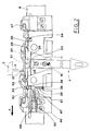
- reference numeral 1 generally indicates the device that moves the yarn carrier 2 in a flat knitting machine.
- This machine includes a cam carrier carriage 3 that is made movable in horizontal directions over a pair of needle beds 4, which have grooves in which there are slidingly inserted respective needles.
- the carriage 3 is equipped with small anchors 5, which are movable vertically and designed for trailing the moving device 1 in opposite directions, as it will be better explained in the following.
- a bar 6 overlies the needle beds 4 and is parallel thereto, so as to support the moving device 1 with possiblility of movements.
- the moving device 1 includes a slide 7 that is slidably mounted on the bar 6 and that is equipped with locking means 8 simmetrically mounted at both its opposite ends respectively. In one side of the slide 7, in a middle position, there is a recess 10 made in the body 9 of the slide.
- the arm 12 is fixed to the attachment guide 11 by means of a couple of screws 13 that pass through respective slots 14 made in the same arm 12.
- the assembly made up by the attachment guide 11 and the yarn carrier 2 is pivoted to the body 9 of the slide 7, by means of a pin 15 transverse to the body 9, so that the assembly can oscillate in a plane longitudinal to the device.
- Actuating means 16 for controlling the oscillatory motion of the yarn carrier 2 are positioned over the body 9 of the slide 7, and include substantially a first shaped rod 17 and a second shaped rod 18, which are positioned side by side and which can slide in a direction that is longitudinal to the slide 7.
- the rods 17 and 18 are guided in the spaces delimited by a pair of guides 19 which are simmetrically made at the opposite ends of the body 9.
- the second rod 18 is pivoted centrally by means of a transverse pin 20 that passes through a slot 21 made in a tailpiece 22 of the attachment guide 11 of the yarn carrier 2.
- the first rod 17 has the ends protruding from the body 9 of the slide 7, bent upwards and then toward each other in "U"-like shape, so as to define symmetrical extensions 23 extending on a side of the same rod 17 and located in correspondence with the bendings.
- the second rod 18 has also extensions 24 made at its ends, which are axially shorter than the extensions 23 of the first rod 17.
- the extensions 24 have an angle transverse profile, that is in fact complementar to the profile of the extensions 23.
- the extensions 23, 24 are designed for making a frontal stop for the small anchors 5 of the carriage 3.
- the rods 17, 18 feature, along their lower edges, respective protrusions 25 which are in central positions and bevelled with respect to the motion directions.
- the protrusions 25 push on the upper side of a flexion spring plate 26, or leaf spring, that is supported by the body 9 in adjacency of the recess 10.
- the spring plate has the task of stabilizer.
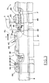
- the lower edges of the rods 17, 18 also present, in symmetrical positions, two respective shaped profiles, each of which includes three notches. More precisely, the first rod 17 presents, starting from each end, the notches 27, 28 and 29.
- the first notch 27 has a side facing towards the center of the slide, this side being bevelled, and a shoulder on the opposite side, while each of the other notches 28 and 29 has both the sides bevelled.
- the second rod 18 has, starting from each end, the notches 30, 31 and 32, which have the sides facing the center of the slide which are bevelled, and shoulders on the opposite side.
- the above mentioned notches made in the rods 17, 18 are struck in turn by the head 33 of a ratchet 34 that is positioned at each end of the slide body 9.
- the ratchet 34 is slidably mounted into a vertical seat 35 that is made in the body 9, from which the ratchet head 33 protrudes, the ratchet being subjected to the action of a spring 36.
- the upper ridge of the slide 7 body 9 features two trailing teeth 37 which define respective front stop planes for the small anchors 5.
- the trailing teeth are located in symmetrical positions, aside of the rods 17, 18.
- Two rockers 38 are pivoted to the slide 7 body 9, in symmetrical position, and are each adjacent to a respecttive trailing tooth 37.
- the rockers can rotate about respective pins 39.
- the two rockers 38 have each a first arm 40 and a second arm 41, which are perpendicular to each other.
- the first arm 40 extends lengthwise, with respect to the slide 7, and towards the center of the body 9; while the second arm 41 extends downwards in correspondence with a cavity 42 made in a side of the body 9.
- the first arm 40 is tapered at the free end, so as to form a first track 43.
- a second track is formed between the arms 40 and 41.
- the second arm 41 of the rockers 38 is adapted to push on the head of a stem 45, that passes through every locking means 8, lengthwise with respect to the device.
- the lock 8 is formed by a prismatic body 46 that is linked to the slide 7 by means of a screw 47 inserted into a central seat 48 and engaging the front wall of the slide 7 body 9.
- the prismatic body 46 has a dovetail channel 49, through which it is slidingly supported by the bar 6, leaving a proper clearance.
- the prismatic body 46 is made up of two prismatic elements 46a and 46b joined together, so that it is made possible to adjust the channel 49 making up for wear occurence and the like.
- the lock 8 is pushed against the body 9 of the slide 7 by a spring 50 that acts onto the head of the screw 47 and on the bottom of the seat 48.
- the seat 48 is properly larger than the screw 47, so that the body 46 of the lock is allowed to rotate between a position in which the slide 7 is free to run, and a position in which the slide 7 is blocked to the bar 6.
- the lower part of the body 46 is held in abutment on a tooth 51 made in the front wall of the slide 7 body 9.
- This tooth 51 in fact acts as a rotation center for the body 46 of the lock 8.
- the upper part of the body 46 of the lock 8 has a cam-like protrusion 52.
- This cam 52 forms an ascending track 53 turned towards the center of the slide 7, then a descending track 54, a horizontal track 55 and a further descending track 56.
- Shifting the lock 8 to the slide releasing position is actuated by means of a related unlocking device 57 that is made up of a further rod 58 that is slidably guided over the body 9, in a direction parallel to the rods 17, 18 of the actuating means 16, so that it comes out from the front wall of the body 9.
- the rod 58 has, at the end turned towards the center of the slide 7, a small block 59 that defines a frontal stop plane.
- the block 59 has a longitudinal slot 60, and the pin 39 of the related rocker 38 passes through this slot.
- the block 59 is in fact struck before than the tooth 37 by the small anchor 5, so that the rod 58 of the unlocking device 57 is axially moved, and the related lock 8 is rotated to a position in which the slide 7 is free to run.
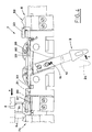
- the ratchets 34 of the slide 7 engage with the central notches 28, 30 of the rods 17, 18 causing the yarn carrier 2 to be vertical.
- the slide 7 comes in contact with a further similar slide 7a, that has the task of running the subsequent stroke strap.
- the further slide 7a is also mounted on the bar 6. (see Fig. 3).
- the contact occurs in correspondence with the stems 45 which pass through the locks positioned at the opposed ends.
- the stems 45 are then axially moved inwardly into the slides 7 and 7a (as shown by the arrow B) so as to push the arms 41 of the related rockers 38, thus provoking the angular rotation of the arm 40 in the direction indicated by the arrow C.
- the small anchor 5 Because of the rotation of the arm 40, the small anchor 5 is pushed upwards so that it disengages from the trailing tooth 37 and from the block 59. The disengagement of the small anchor 5 from the block 59 makes the rod 58 of the unlocking device 57 free, so that the body 46 of the related lock 8 rotates under the action of the spring 50 and the slide 7 results to be blocked to the bar 6.
- the locking occurs substantially in correspondence with the point indicated by F in Fig. 3, where the outer extremity of the channel 49 of the lock body 46 faces the lower face of the bar 6.
- the locking is obviously made by the lock 8 positioned at the fore-part of the slide 7, with respect to the motion direction, which pushes with its head on the bar 6, while the rear lock is inactive.
- the first rod 17 is then moved axially by the small anchor 5, for a short strap equal to the difference between the axial length of the extensions 23 and 24 of the rods 17 and 18, until the inner edges of the extensions 23 and 24 are lined up with each other.
- the notches of the rods 17 and 18 are then displaced with respect to each other.
- the shifting of the first rod 17 also causes the ratchets 34 to be released, so that they can move to a retracted position inside the body 9 in contrast with the related spring 36 (arrow D).
- the shifting of the rod 18 provokes the oscillation of the arm 12 of the yarn carrier 2 about the pin 15, as indicated by the arrow E in Fig. 4.
- the yarn carrier 2 rotates from the vertical working position 2a to a sloping position, so as to allow access to the zone where the second yarn carrier replaces the first one, so that the yarn carriers do not hinder each other.
- the small anchor 5 follows the profile defined by the cam 52 made on the upper wall of the lock body 46.
- the track 56 and 54 of the cam provoke the progressive raising of the small anchor 5 that, at the end of the stroke, disengages from the extensions 23 and 24 of the rods 17 and 18, as shown by the broken line 5c.
- the small strikes the track 53 of the related cam of the slide 7a, as indicated by 5d, to trail the second yarn carrier along the respective working stroke.
- the ratchets 34 spring one to the inside of the notches 29 and 32 of the rods 17 and 18, and the other one to the inside of the opposed notches 27 and 30 (arrow G) so that the locking of the yarn carrier 2 in the sloping position is safely made.
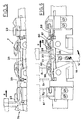
- Figs. 5 and 6 there are shown the locking and trailing phases for the slide 7 in the return stroke of the carriage 3 in direction R.
- the small anchor 5, that releases the slide 7a runs downwards along the track 53 and strikes first the extension 23 of the first rod 17, that protrudes outwardly with respect to the corresponding extension 24 of the second rod 18. In this way the outer edges of the two extensions 23 and 24 are lined up with each other, and then the small anchor 5 moves both the rods 17 and 18 in synchrony.
- the relative displacement between the two rods 17 and 18 causes the ratchets 34 to partially release (see Fig. 5).
- the synchronic shifting of the rods 17 and 18 provokes the oscillation of the yarn carrier 2 that takes again the vertical position.
- the small anchor 5 then runs along the track 44 of the rocker 38, that is located upstream with respect to the direction R, so as to rise along the arm 40 of this rocker 38 thus overcoming the related tooth 37 (position 5i).
- the small anchor 5 then goes to strike the block 59 of the unlocking device 57 for the lock 8 located downstream with respect to the direction R.
- the rod 58 of the unlocking device 57 is therefore moved axially so as to provoke, in the way already described, the rotation of the body 46 of this lock 8, up to a position that allows the free run of the slide 7 along the bar 6.
- the advancement of the slide 7 occurs when the small anchor 5 moves the block 59 and strikes the related trailing tooth 37.
- the yarn carrier 2 is in fact kept in the vertical active position, so that the yarn is delivered to the group of working needles.
- the carraige 3 instead goes on with its stroke so as to engage a further slide 7a by means of the small anchor 5.
- the slide 7a is released and trailed along the bar 6 for the respective working stroke in a way similar to the one for the previously selected slide 7.
- the vertical position is taken again by the yarn carrier 2 when the carriage 3 runs the return stroke in direction R, and joins again the first slide 7.
- the yarn carrier is again rotated to take the sloping position opposite to the movement direction R.
- Figs. 7 amd 8 there is shown a different embodiment of the subject device, this embodiment being particularly designed to be used in those cases where a limited oscillation is requested for the yarn carrier 2.
- the arm 12 of the yarn carrier 2 is slidably mounted lengthwise in the attachment guide 11 and is connected with the pin 15 by means of a slot 61 made by a protrusion 62 extending from the same attachment guide 11.
- the slot 61 is open downwards while the slot 21 of the upper tailpiece 22 of the attachment guide 11, into which the pin 20 of the yarn carrier actuating means 16 engage.
- the pin 15 is supported by a plate 63 fixed to the lower part of the slide body 9 so as to result in a position that is lowered with respect to the embodiment previously described.
- the attachment guide 11 has a roller 64 positioned at its back, idling about a horizontal axis transverse to the bar 6.
- the roller 64 runs into a groove 65 that is made in correspondence of the recess 10 of the body 9 and that forms two paths downwardly converging.
- the groove 65 defines in fact a cam that is adapted for provoking the upward shifting of the yarn carrier 2 during its rotation to the sloping release position.
- the yarn carrier 2 In the vertical trailing position shown in Fig. 7, the yarn carrier 2 is located at a lowered position defined by the vertex turned downwards of the groove 65.
- the roller 64 is instead caused to follow the respective ascending path of the groove 65 (see Fig. 8).
- the yarn carrier 2 therefore rotates from a vertical working position 2a to a position that is opposite to the current movement direction and makes, at the same time, a displacement upwards.
- the upward displacement of the yarn carrier 2, with respect to the pin 15 that is in turn moved to a lower position of the slide body 9, allows to limit the extent of the yarn carrier 2 oscillation in the release phase, without any change for the rod 18 stroke.
Landscapes
- Engineering & Computer Science (AREA)
- Textile Engineering (AREA)
- Knitting Machines (AREA)
Claims (7)
- Dispositif pour déplacer l'entraíneur de fil d'une machine à tricoter à plat comprenant un charriot (3) se déplaçant horinzontalement sur une paire de bancs d'aiguilles (4) dôtés de rainures dans lesquelles sont glissées les aiguilles respectives, le charriot étant équipé d'au moins une petite ancre (5) qui se déplace verticalement et a pour fonction de traíner une glissière (7) dans les directions (A, R) parallèlement aux bancs d'aiguilles, cette glissière (7) soutient un entraíneur de fil (2) et est est monté latéralement sur une barre (6) placée au-dessus des bancs d'aiguilles (4) susmentionnés, et parallèle à ceux-ci, la glissière (7) étant également équipée de deux dents d'entraínement (37) propres à être engagées dans ladite petite ancre (5) pour entraíner la glissière dans les deux directions de déplacement (A, R) parallèlement aux bancs d'aiguilles, et avec deux balanciers (38) qui se balancent sur des broches respectives (39) pour désengager ladite petite ancre (5) des dents d'entraínement (37) susmentionnées, le dispositif étant caractérisé en ce qu'il comprend :
des moyens de blocage (8) montés symétriquement aux extrémités opposées de ladite glissière (7) pour bloquer la glissière (7) en question sur la barre (6) ;
des moyens d'action (16) pour que ledit entraíneur de fil (2) oscille entre une position de travail dans laquelle il est vertical et une position dans laquelle il glisse dans une direction opposée à la direction de déplacement (A, R) de la glissière, de façon à ce que la position de travail soit laissée libre, lesdits moyens d'action comprenant une premiere tige (17) et une deuxième tige (18), la deuxième tige (18) étant pivotée sur une position centrale de l'entraíneur de fil (2) susmentionné, lesdites tiges (17, 18) étant placées côte à côte et coulissant dans le sens de la longueur par rapport à la glissière (7) et étant dotées à leurs extrémités opposées de prolongements (23, 24) propres à être frappés par ladite petite ancre (5) pendant son déplacement dans l'une des deux directions (A, R) parallèlement aux bancs d'aiguilles, les dits prolongements (23) de la première tige (17) ayant un axe plus long que les deuxièmes prolongements (24) de la deuxième tige (18) de façon à être frappés par ladite petite ancre (5) avant lesdits deuxièmes prolongements (24) de la deuxième tige (18). - Dispositif selon la revendication 1, caractérisé en ce que lesdites tiges (17, 18) ont, le long des bordures inférieures et dans des positions symétriques, deux profils de formes respectives, chaque profil comprenant trois encoches (27, 28, 29, 30, 31, 32) conçues pour recevoir, tour à tour la tête (33) d'un cliquet (34) situé à côté de chaque extrémité du bâti (9) de la glissière (7), lequel cliquet coulisse verticalement et est soumis à des moyens élastiques (36) de façon à pousser l'entraíneur de fil (2) en position verticale durant la frappe de la glissière (7) lorsque celle-ci est sélectionnée et de façon à placer l'entraíneur de fil (2) dans ladite position de coulissement à la fin de la frappe susmentionnée.
- Dispositif selon la revendication 1, caractérisé en ce que lesdits moyens de blocage (8) comprennent respectivement un bâti (46) associé à ladite glissière (7) au moyen de vis (47) insérées dans un logement élargi (48) ménagé dans le bâti (46), lequel bâti (46) est poussé contre le bâti (9) de la glissière (7), par des moyens de ressort (50), et présente une chaíne (49) par laquelle ladite barre (6) le porte en laissant un espace suffisant, de façon à ce que ce même bâti (46) puisse tourner entre la position dans laquelle la glissière (7) est libre et la position dans laquelle la glissière est bloquée à ladite barre (6).
- Dispositif selon la revendication 1, caractérisé en ce que ledit blocage (8) est équipé d'un dispositif de déblocage (57) qui comprend une tige (58) coulissant à l'intérieur de guide dans le sens de la longueur par rapport à ladite glissière (7) de façon à sortir de la paroi avant du bâti (9) de la glissière, ladite tige comprenant aussi une cale (59) placée à l'extrémité de la tige tourné vers le centre de la glissière (7), cette cale (59) définissant un plan d'arrêt pour ladite petite ancre (5).
- Dispositif selon la revendication 3, caractérisé en ce que ledit bâti (46) du blocage (8) comprend une came (52) ménagée à son sommet, cette came étant suivie de ladite petite ancre (5) et formant une piste ascendante (53), une piste descendante (54), une piste horizontale (55) et une autre piste descendante (56), dirigées vers le centre de la glissière (7).
- Dispositif selon la revendication 3, caractérisé en ce que ledit bâti (46) du blocage (8) est élastiquement gardé en butée sur une dent (51) ménagée dans la paroi avant du bâti (9) de la glissière, cette dent étant conçue pour agir comme un centre de rotation pour le bâti (46) en question.
- Dispositif selon la revendication 1, caractérisé en ce que ledit entraíneur de fil (2) supporte un rouleau (64) articulé sur une poutre d'axe horinzontal à ladite barre (6) et passant à l'intérieur d'une fente (65) ménagée dans le bâti (9) de la glissière, cette fente définissant deux chemins qui convergent symétriquement et vers le bas de façon former une came conçue pour remonter l'entraíneur de fil (2) lorsque qu'il se tourne dans la position de coulissement.
Applications Claiming Priority (4)
| Application Number | Priority Date | Filing Date | Title |
|---|---|---|---|
| ITBO920205A IT1257805B (it) | 1992-05-25 | 1992-05-25 | Dispositivo per la movimentazione del guidafilo in una macchina rettilinea per maglieria |
| ITBO920205 | 1992-05-25 | ||
| ITBO930041 IT1266249B1 (it) | 1993-02-12 | 1993-02-12 | Dispositivo per la movimentazione del guidafilo in una macchina rettilinea per maglieria. |
| ITBO930041 | 1993-02-12 |
Publications (2)
| Publication Number | Publication Date |
|---|---|
| EP0572360A1 EP0572360A1 (fr) | 1993-12-01 |
| EP0572360B1 true EP0572360B1 (fr) | 1998-09-23 |
Family
ID=26330275
Family Applications (1)
| Application Number | Title | Priority Date | Filing Date |
|---|---|---|---|
| EP19930830220 Expired - Lifetime EP0572360B1 (fr) | 1992-05-25 | 1993-05-25 | Dispositif pour le mouvement des coulisseaux pour un métier à tricoter rectiligne |
Country Status (3)
| Country | Link |
|---|---|
| EP (1) | EP0572360B1 (fr) |
| DE (1) | DE69321162T2 (fr) |
| ES (1) | ES2120492T3 (fr) |
Cited By (2)
| Publication number | Priority date | Publication date | Assignee | Title |
|---|---|---|---|---|
| EP1788132A1 (fr) | 2005-11-17 | 2007-05-23 | H. Stoll GmbH & Co. KG | Guide-fil pour métier à tricoter rectiligne |
| DE102010033024B4 (de) * | 2010-07-31 | 2013-09-19 | H. Stoll Gmbh & Co. Kg | Fadenführer für eine Flachstrickmaschine und Flachstrickmaschine |
Families Citing this family (9)
| Publication number | Priority date | Publication date | Assignee | Title |
|---|---|---|---|---|
| KR100867140B1 (ko) * | 2001-03-29 | 2008-11-06 | 가부시키가이샤 시마세이키 세이사쿠쇼 | 횡편기의 얀 피더 |
| CN100519866C (zh) * | 2001-07-24 | 2009-07-29 | 株式会社岛精机制作所 | 横机的喂纱装置及横机的喂纱方法 |
| JP4125267B2 (ja) * | 2004-07-07 | 2008-07-30 | 株式会社島精機製作所 | 横編機における給糸装置のヤーンフィーダ |
| CN100408742C (zh) * | 2006-04-07 | 2008-08-06 | 冯加林 | 嵌花梭箱 |
| EP2037027B1 (fr) * | 2007-09-11 | 2011-08-31 | H. Stoll GmbH & Co. KG | Guide-fil pour machine à tricoter rectiligne |
| CN102433660A (zh) * | 2010-09-29 | 2012-05-02 | 吴江市华英纺织品有限公司 | 引线偏转装置 |
| CN103205858B (zh) * | 2013-01-08 | 2014-11-05 | 福建睿能科技股份有限公司 | 一种防撞针嵌花纱嘴控制系统及方法 |
| CN103924373B (zh) * | 2014-04-22 | 2015-10-21 | 新昌县镜岭镇康柳电子元件厂 | 一种横机的导纱器限位装置 |
| JP7048392B2 (ja) * | 2018-03-30 | 2022-04-05 | 株式会社島精機製作所 | 横編機 |
Family Cites Families (4)
| Publication number | Priority date | Publication date | Assignee | Title |
|---|---|---|---|---|
| IT1037710B (it) * | 1975-04-29 | 1979-11-20 | Zamark Srl | Dispositivo guidafili per macchine rettilinee da maglieria |
| DE2730306C2 (de) * | 1977-07-05 | 1985-01-03 | H. Stoll Gmbh & Co, 7410 Reutlingen | Verfahren und Flachstrickmaschine zur Herstellung von Intarsienware |
| DE3716931C1 (de) * | 1986-07-01 | 1988-01-28 | Stoll & Co H | Fadenfuehrerschlitten |
| IT214303Z2 (it) * | 1988-03-01 | 1990-05-03 | Emm Srl | Dispositivo perfezionato per il supporto del guidafilo di una macchina automatica rettilinea per maglieria |
-
1993
- 1993-05-25 DE DE1993621162 patent/DE69321162T2/de not_active Expired - Fee Related
- 1993-05-25 ES ES93830220T patent/ES2120492T3/es not_active Expired - Lifetime
- 1993-05-25 EP EP19930830220 patent/EP0572360B1/fr not_active Expired - Lifetime
Cited By (3)
| Publication number | Priority date | Publication date | Assignee | Title |
|---|---|---|---|---|
| EP1788132A1 (fr) | 2005-11-17 | 2007-05-23 | H. Stoll GmbH & Co. KG | Guide-fil pour métier à tricoter rectiligne |
| CN1966797B (zh) * | 2005-11-17 | 2011-10-05 | H.斯托尔两合公司 | 用于横机的导纱器 |
| DE102010033024B4 (de) * | 2010-07-31 | 2013-09-19 | H. Stoll Gmbh & Co. Kg | Fadenführer für eine Flachstrickmaschine und Flachstrickmaschine |
Also Published As
| Publication number | Publication date |
|---|---|
| EP0572360A1 (fr) | 1993-12-01 |
| DE69321162D1 (de) | 1998-10-29 |
| ES2120492T3 (es) | 1998-11-01 |
| DE69321162T2 (de) | 1999-02-18 |
Similar Documents
| Publication | Publication Date | Title |
|---|---|---|
| EP0572360B1 (fr) | Dispositif pour le mouvement des coulisseaux pour un métier à tricoter rectiligne | |
| US5475991A (en) | Sinker mechanism for flat knitting machines having yarn drop prevention part | |
| KR101395171B1 (ko) | 싱커 없이 래치 니들을 구비한 편물기 | |
| US4442683A (en) | Stitch pressing device for flat knitting machine | |
| US6510712B2 (en) | Sliding-tongue compound needle for a knitting machine | |
| US6233977B1 (en) | Compound needle having a divided closing element | |
| JP2019531424A (ja) | 編機又は縦編機におけるステッチ形成のためのニードル、複数のかかるニードルを有する編機又は縦編機、及びかかるニードルの製造方法 | |
| JP3333304B2 (ja) | 可動糸ガイド部材を備えた横編機 | |
| EP0751248B1 (fr) | Came de tricotage et de report pour métier à tricoter rectiligne | |
| CN101018901B (zh) | 横机的喂纱装置的纱线供给器 | |
| CS264320B2 (en) | The knitting machine with at least one needle bar plate | |
| EP1835059B1 (fr) | Systeme de came combinee | |
| US20040093910A1 (en) | Device for machine knitting | |
| EP0603006B1 (fr) | Platine de report pour un métier à tricoter rectiligne | |
| GB1588190A (en) | Warp knitting machines | |
| CS257767B2 (en) | Knitting frame | |
| EP1655398B1 (fr) | Metier a mailles cueillies a platine d'abattage mobile | |
| KR100732360B1 (ko) | 루프-형성 시스템용 니들 | |
| ITTO990967A1 (it) | Meccanismo d'azionamento di un ago composito per maglieria in una macchina per maglieria all'uncinetto ad altezza ridotta. | |
| KR100768345B1 (ko) | 코 이동 기구를 구비하는 횡편기 | |
| US2823528A (en) | Needle bar assembly and method of knitting | |
| US7047769B2 (en) | Loop-forming system and sinker for such a system | |
| JP2005048338A (ja) | 可動シンカーを備える横編機 | |
| US2077719A (en) | Hooked rug making device | |
| JPH07197359A (ja) | シャトル・コンパウンド・ニードル |
Legal Events
| Date | Code | Title | Description |
|---|---|---|---|
| PUAI | Public reference made under article 153(3) epc to a published international application that has entered the european phase |
Free format text: ORIGINAL CODE: 0009012 |
|
| AK | Designated contracting states |
Kind code of ref document: A1 Designated state(s): CH DE ES IT LI |
|
| 17P | Request for examination filed |
Effective date: 19940530 |
|
| 17Q | First examination report despatched |
Effective date: 19960208 |
|
| GRAG | Despatch of communication of intention to grant |
Free format text: ORIGINAL CODE: EPIDOS AGRA |
|
| GRAG | Despatch of communication of intention to grant |
Free format text: ORIGINAL CODE: EPIDOS AGRA |
|
| GRAH | Despatch of communication of intention to grant a patent |
Free format text: ORIGINAL CODE: EPIDOS IGRA |
|
| GRAH | Despatch of communication of intention to grant a patent |
Free format text: ORIGINAL CODE: EPIDOS IGRA |
|
| ITF | It: translation for a ep patent filed | ||
| GRAA | (expected) grant |
Free format text: ORIGINAL CODE: 0009210 |
|
| AK | Designated contracting states |
Kind code of ref document: B1 Designated state(s): CH DE ES IT LI |
|
| REG | Reference to a national code |
Ref country code: CH Ref legal event code: NV Representative=s name: R. A. EGLI & CO. PATENTANWAELTE Ref country code: CH Ref legal event code: EP |
|
| REF | Corresponds to: |
Ref document number: 69321162 Country of ref document: DE Date of ref document: 19981029 |
|
| REG | Reference to a national code |
Ref country code: ES Ref legal event code: FG2A Ref document number: 2120492 Country of ref document: ES Kind code of ref document: T3 |
|
| PLBE | No opposition filed within time limit |
Free format text: ORIGINAL CODE: 0009261 |
|
| STAA | Information on the status of an ep patent application or granted ep patent |
Free format text: STATUS: NO OPPOSITION FILED WITHIN TIME LIMIT |
|
| 26N | No opposition filed | ||
| PGFP | Annual fee paid to national office [announced via postgrant information from national office to epo] |
Ref country code: ES Payment date: 20040416 Year of fee payment: 12 |
|
| PGFP | Annual fee paid to national office [announced via postgrant information from national office to epo] |
Ref country code: CH Payment date: 20040525 Year of fee payment: 12 |
|
| PGFP | Annual fee paid to national office [announced via postgrant information from national office to epo] |
Ref country code: DE Payment date: 20040726 Year of fee payment: 12 |
|
| PG25 | Lapsed in a contracting state [announced via postgrant information from national office to epo] |
Ref country code: IT Free format text: LAPSE BECAUSE OF NON-PAYMENT OF DUE FEES;WARNING: LAPSES OF ITALIAN PATENTS WITH EFFECTIVE DATE BEFORE 2007 MAY HAVE OCCURRED AT ANY TIME BEFORE 2007. THE CORRECT EFFECTIVE DATE MAY BE DIFFERENT FROM THE ONE RECORDED. Effective date: 20050525 |
|
| PG25 | Lapsed in a contracting state [announced via postgrant information from national office to epo] |
Ref country code: ES Free format text: LAPSE BECAUSE OF NON-PAYMENT OF DUE FEES Effective date: 20050526 |
|
| PG25 | Lapsed in a contracting state [announced via postgrant information from national office to epo] |
Ref country code: LI Free format text: LAPSE BECAUSE OF NON-PAYMENT OF DUE FEES Effective date: 20050531 Ref country code: CH Free format text: LAPSE BECAUSE OF NON-PAYMENT OF DUE FEES Effective date: 20050531 |
|
| PG25 | Lapsed in a contracting state [announced via postgrant information from national office to epo] |
Ref country code: DE Free format text: LAPSE BECAUSE OF NON-PAYMENT OF DUE FEES Effective date: 20051201 |
|
| REG | Reference to a national code |
Ref country code: CH Ref legal event code: PL |
|
| REG | Reference to a national code |
Ref country code: ES Ref legal event code: FD2A Effective date: 20050526 |