EP0572317A1 - Mehrfachkontakt-Anschlussklemme - Google Patents
Mehrfachkontakt-Anschlussklemme Download PDFInfo
- Publication number
- EP0572317A1 EP0572317A1 EP93401340A EP93401340A EP0572317A1 EP 0572317 A1 EP0572317 A1 EP 0572317A1 EP 93401340 A EP93401340 A EP 93401340A EP 93401340 A EP93401340 A EP 93401340A EP 0572317 A1 EP0572317 A1 EP 0572317A1
- Authority
- EP
- European Patent Office
- Prior art keywords
- connection
- connection part
- contact
- contact element
- lug
- Prior art date
- Legal status (The legal status is an assumption and is not a legal conclusion. Google has not performed a legal analysis and makes no representation as to the accuracy of the status listed.)
- Granted
Links
Images

Classifications
-
- H—ELECTRICITY
- H01—ELECTRIC ELEMENTS
- H01R—ELECTRICALLY-CONDUCTIVE CONNECTIONS; STRUCTURAL ASSOCIATIONS OF A PLURALITY OF MUTUALLY-INSULATED ELECTRICAL CONNECTING ELEMENTS; COUPLING DEVICES; CURRENT COLLECTORS
- H01R13/00—Details of coupling devices of the kinds covered by groups H01R12/70 or H01R24/00 - H01R33/00
- H01R13/40—Securing contact members in or to a base or case; Insulating of contact members
- H01R13/42—Securing in a demountable manner
- H01R13/428—Securing in a demountable manner by resilient locking means on the contact members; by locking means on resilient contact members
- H01R13/432—Securing in a demountable manner by resilient locking means on the contact members; by locking means on resilient contact members by stamped-out resilient tongue snapping behind shoulder in base or case
Definitions
- the field of the invention is that of the connection of electrical conductors and relates to a multi-contact connection terminal. More specifically, the present invention relates to a connection terminal of this type ensuring maintenance of the electrical contacts in their housings.
- Connection terminals are known as shown in FIG. 1.
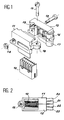
- FIG. 1 is an exploded perspective view of a connection assembly comprising a terminal 10 and two metal shells 11,12 intended to constitute an electromagnetic shielding of the terminal 10.
- the terminal 10 is for example of the type BPS 8B21 AC D0Z1 of at BURNDY and the shells manufactured by the company Alcatel Transmission and referenced T0 204 850 0000.
- Terminal 10 consists of an insulating box comprising housings for holding and insulating electrical contacts. These contacts are usually female contacts each comprising a tulip at one of their ends, intended to cooperate with a male pin, the other end serving for connection of the contact to an insulated electrical conductor. This connection is usually made by crimping.
- the shells 11 and 12 are assembled, after having inserted the terminal 10 therebetween, using a screw-nut assembly 13, 14 and a semi-threaded screw 15 cooperating with threads produced in a set of hinges 16,17,18 threaded.
- FIG. 2 is a bottom view of the connection assembly of the figure after connection of electrical wires to the contacts of terminal 10 and assembly of the elements 10, 11 and 12.
- each cable 20 to 23 has two conductors insulated and a ground braid previously stripped to be in electrical contact with the shells 11 and 12.
- the insulated conductors are each connected to a contact of the pin 10, six contacts being left free.
- the dimensions of the shielding shells are provided so that no electrical conductor connected to a contact comes into electrical contact with these shells and that a minimum insulation distance is ensured. Electromagnetic shielding of the conductors and the connector is thus effectively ensured.
- Such shielding is used in particular in the field of telephony, which increasingly uses shielded cables, conductors and connectors.
- connection assembly The main drawback of this connection assembly is observed when the assembly is opened, that is to say during the separation of the two shells. Such a separation takes place in particular to carry out maintenance operations (checking of the contacts, modification of the wiring, etc.), and there is a partial drive of the electrical conductors which are trapped, by means of the shielding braid, in the slots 19 of the shells.
- This partial drive causes an irreversible bending of the contacts of the terminal 10 and, during reassembly of the connection assembly, the contacts thus deformed can come to touch the internal wall of the shells 11 and 12, thus causing a short circuit.
- connection terminals have provided means for maintaining the contacts, preventing them from bending when a stress is applied to the conductors which are connected to it, this stress having the effect of moving the contacts away from the notches in which they are engaged.
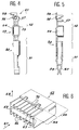
- FIG. 3 is a perspective view of part of a connection terminal 30 comprising housings 31 to 34 for receiving metallic contact elements, of which only a part, referenced 35, is shown.
- Each housing consists of a cell 36 extending a notch 37 in the general shape of a U, consisting of a bottom 38 and two side walls 39.40.
- Each contact element comprises a plug-in part penetrating into one of the cells 36 and a connection part 35 intended for fixing an electrical conductor.
- the electrical conductor is fixed by crimping, this crimping consisting in inserting the electrical conductor in a self-stripping slot, here consisting of two cutting blades 41 and 42 cooperating with identical blades which face them in notch 37.
- the cutting blades 41 and 42 are carried by a vertical plate 43 resting by one of its short sides on the bottom 38 of the notch 31, this plate 43 being pressed by elasticity of the contact against a side wall of the notch.
- mechanical holding means constituted by shoulders 44 to 47 maintain the connection part 37 of a contact element in its notch.
- connection terminal has a height of 2H greater than the terminal shown in Figure 1 not comprising such means for holding the connection parts.
- the presence of these shoulders be compensated by a reduction in the height of the notches, since such a reduction necessarily results in a reduction in the height of the blades 41 and 42, which cannot be achieved when one wishes to maintain their quality of incision of the insulation surrounding the electrical conductor. If the height of the terminal is increased, it can no longer enter shells as described with reference to Figure 1 and in addition, the width L available for the passage of the insertion and crimping tool is narrowed, which makes these operations more delicate.
- the present invention aims in particular to overcome these drawbacks.
- one of the objectives of the invention is to provide a connection terminal in which the contact elements are held at the bottom of the notches when a traction in a direction tending to separate them is applied to the electrical conductors connected to these elements of contact.
- Another objective is to provide such a terminal having a reduced bulk allowing it to be combined with existing shielding shells, in particular those described previously with reference to FIGS. 1 and 2.
- connection terminal of the type consisting of an insulating housing comprising housings for receiving metal contact elements, each housing consisting of a cell extending a notch in the general U shape consisting of a bottom and two side walls, each contact element comprising a plug part penetrating a cells and a connection part of an electrical conductor, the connection part being held in the notch of the housing by mechanical holding means constituted by a lug formed in the connection part and projecting relative to the part connecting this contact element in a direction substantially perpendicular to the plane of symmetry of the general U-shape, the lug penetrating into a slot made at the base of the side wall when the contact element is fully engaged in one of the housings to hold the connection part against the bottom of the notch, the connection parts each have one a recess at their lug so that a minimum distance between contact elements is respected between two contact elements engaged in contiguous housings of the insulating housing when the contact elements
- the recess made makes it possible to minimize the distance separating two contiguous contact elements.
- the size of the terminal 10 in Figure 1 is not increased.
- the lug is produced at the end of the connection part of the contact element. This arrangement allows effective maintenance of the connection end.
- connection part of each contact element may also comprise at least one self-stripping slot intended to cut the insulation surrounding the electrical conductor and to come into electrical contact with the electrical conductor when the latter is forced into this slot.
- This embodiment therefore consists in securing the electrical conductor and the contact element by crimping.
- connection part of each contact element may include foldable pins intended to enclose the insulation of the electrical conductor. The mechanical retention between the electrical conductor and the contact element is thus improved.
- FIG 4 is a top view of a contact element according to the present invention.
- a contact element generally referenced by 50, is constituted by a metal sheet cut and folded so as to have the shape shown.
- the contact element 50 is a female element intended to cooperate with a male pin thanks to a plug-in part 51, here constituted by a tulip.
- the plug-in part is extended by a connection part 52 intended for electrical and mechanical connection with an electrical conductor.
- the plug-in part 51 consists of two flexible elastic blades 59, 60 between which a male pin can slide to establish electrical contact.
- the plug-in part 51 is included, when it is fully inserted in the insulating housing of the connection terminal, in a rectangular cell of this housing.
- the connection part 52 has a self-stripping slot 53 consisting of two cutting blades 54 and 55 intended to cut the insulation of the electrical conductor when the latter is crimped between the two blades 54,55 using a tool. appropriate.
- Foldable pins 56, 57 can also be provided on this connection part 52, intended to enclose the insulation surrounding the electrical conductor in order to maintain it.
- connection part also comprises a lug 58, preferably at its end as shown, this lug having the function of ensuring the maintenance of this connection part 52 against the bottom of the notch in which the contact element is engaged , as will be described more precisely below.
- This lug 58 produced in the connection part, projects in relation to the connection part to cooperate with one of the side walls delimiting the notch for receiving the contact element.
- a recess 61 is provided, its function being described below.
- FIG. 6 is a perspective view of an insulating box comprising housings for receiving contact elements in accordance with FIGS. 4 and 5.
- the housing generally referenced by 62, comprises 2 rows of 7 housings for receiving contact elements, each housing consisting of a cell 63 extended by a notch 64.
- the cells 63 are of generally rectangular shape and receive the plug-in parts 51 of the contact elements 50 and the notches 64 receive the connection parts 52 of these same contact elements 50.
- Each notch 64 has a general shape of U and consists of a bottom 69 and two side walls 70 which delimit it.
- the housing considering only one side of the housing and that such a housing has eight side walls 70 separating seven contact elements, counting the end walls, at least seven side walls have a slot 65 made at their end, of size slightly larger than that of the lug 58.
- the slots are identical and made so that a lug can engage in a slot 65 when engaging the contact element in its receiving housing.
- the slots 65 are produced by molding the housing 62 at the height of the pins 58 relative to the bottom of the notches. If these pins are made at the base of the contact elements, as shown in FIG. 5, the slots 65 give on the bottom 69 notches 64.
- the lug protrudes relative to the connection part of its contact element in a direction substantially perpendicular to the plane of symmetry of the general U-shape of the notch, this lug cooperating with a side wall to maintain the part of connection against the bottom of the notch.
- the direction of extension of this lug must therefore be substantially parallel to the bottom of the notch.
- FIG. 7 is a partial perspective view of the connection pin consisting of the insulating housing of FIG. 6 and of contact elements in accordance with FIGS. 4 and 5.
- Three contact elements 50 are shown, each inserted in a housing of the housing 62.
- the pins 58 are engaged in the slots 65 made in the side walls 70 of the notches.
- the recesses 61 made at the lugs 58 allow a minimum distance between two contiguous contact elements to be respected, this guaranteeing good electrical insulation.
- the shape of the recesses is calculated according to the current creepage lines.
- each lug can be provided in a connection part of a contact element, each lug cooperating for example with a slot made in a side wall. We will then ensure that in front of each lug a recess is provided to minimize the distance separating two contact elements.
- connection part using a lug does not increase the size of the connection terminal according to the invention compared to existing ones and this terminal can therefore be provided with electromagnetic shielding shells existing.
- the crimping tool can also be identical to those existing, since no material is brought to the side walls.
Landscapes
- Details Of Connecting Devices For Male And Female Coupling (AREA)
- Connector Housings Or Holding Contact Members (AREA)
Applications Claiming Priority (2)
| Application Number | Priority Date | Filing Date | Title |
|---|---|---|---|
| FR9206428 | 1992-05-26 | ||
| FR9206428A FR2691845B1 (fr) | 1992-05-26 | 1992-05-26 | Borne de raccordement multi-contacts. |
Publications (2)
| Publication Number | Publication Date |
|---|---|
| EP0572317A1 true EP0572317A1 (de) | 1993-12-01 |
| EP0572317B1 EP0572317B1 (de) | 1996-02-07 |
Family
ID=9430193
Family Applications (1)
| Application Number | Title | Priority Date | Filing Date |
|---|---|---|---|
| EP19930401340 Expired - Lifetime EP0572317B1 (de) | 1992-05-26 | 1993-05-25 | Mehrfachkontakt-Anschlussklemme |
Country Status (3)
| Country | Link |
|---|---|
| EP (1) | EP0572317B1 (de) |
| DE (1) | DE69301498D1 (de) |
| FR (1) | FR2691845B1 (de) |
Citations (5)
| Publication number | Priority date | Publication date | Assignee | Title |
|---|---|---|---|---|
| US3582863A (en) * | 1969-03-12 | 1971-06-01 | Tektronix Inc | Electrical terminal housing having hinge and adjacent lock projection |
| EP0043200A1 (de) * | 1980-06-27 | 1982-01-06 | AMP INCORPORATED (a New Jersey corporation) | Elektrischer Verbinderzusammenbau mit lösbar gehalterten Anschlüssen |
| JPS5786277U (de) * | 1980-11-17 | 1982-05-27 | ||
| US4781628A (en) * | 1987-10-22 | 1988-11-01 | General Motors Corporation | Female electrical terminal |
| WO1990007806A1 (en) * | 1988-12-30 | 1990-07-12 | Amp Incorporated | Electrical connector |
-
1992
- 1992-05-26 FR FR9206428A patent/FR2691845B1/fr not_active Expired - Fee Related
-
1993
- 1993-05-25 EP EP19930401340 patent/EP0572317B1/de not_active Expired - Lifetime
- 1993-05-25 DE DE69301498T patent/DE69301498D1/de not_active Expired - Lifetime
Patent Citations (5)
| Publication number | Priority date | Publication date | Assignee | Title |
|---|---|---|---|---|
| US3582863A (en) * | 1969-03-12 | 1971-06-01 | Tektronix Inc | Electrical terminal housing having hinge and adjacent lock projection |
| EP0043200A1 (de) * | 1980-06-27 | 1982-01-06 | AMP INCORPORATED (a New Jersey corporation) | Elektrischer Verbinderzusammenbau mit lösbar gehalterten Anschlüssen |
| JPS5786277U (de) * | 1980-11-17 | 1982-05-27 | ||
| US4781628A (en) * | 1987-10-22 | 1988-11-01 | General Motors Corporation | Female electrical terminal |
| WO1990007806A1 (en) * | 1988-12-30 | 1990-07-12 | Amp Incorporated | Electrical connector |
Also Published As
| Publication number | Publication date |
|---|---|
| FR2691845B1 (fr) | 1995-10-13 |
| EP0572317B1 (de) | 1996-02-07 |
| DE69301498D1 (de) | 1996-03-21 |
| FR2691845A1 (fr) | 1993-12-03 |
Similar Documents
| Publication | Publication Date | Title |
|---|---|---|
| CA2034494C (fr) | Connecteur electrique pour le raccordement d'un cable multiconducteur blinde a un ensemble electrique place a l'interieur d'un chassis | |
| EP2897234B1 (de) | RJ45-Stecker für elektrisches RJ45-Verbindungskabel | |
| US6676444B2 (en) | Connector for a flat cable and method of assembling it | |
| FR2694456A1 (fr) | Prise femelle de type "modular jack" et à connectique intégrée. | |
| EP0945932A2 (de) | Doppelstecker-Verbindungselement, angepasste Stecker- und Buchsenelemente sowie dazugehörige Verbindungsanordnung | |
| FR2662859A1 (fr) | Assemblage de cable blinde a masse flottante. | |
| EP3682531B1 (de) | Verbindungssystem für eine elektrische maschine | |
| US20060223356A1 (en) | Electrical connector with latching element | |
| FR2648628A1 (fr) | Systeme de connecteurs electriques | |
| EP1271713B1 (de) | Schwachstrom-Modular Jackverbinder | |
| EP0743702A1 (de) | Vorrichtung für elekrtischen Kontakten mit Isolationsverschiebung | |
| FR2504315A1 (fr) | Element de connexion et dispositif de connexion, comportant de tels elements | |
| US8033874B2 (en) | Cable connector with improved contacts ensuring reliable connection with cables | |
| FR2587551A1 (fr) | Connecteur electrique | |
| EP0080389B1 (de) | Elektrischer Kontakt und Verwendung für einen Verbinder | |
| EP0572317B1 (de) | Mehrfachkontakt-Anschlussklemme | |
| WO2008099093A2 (fr) | Prise de raccordement a montage simplifie pour cable multiconducteur | |
| EP0251909B1 (de) | Verbindungselement für ein elektrisches Monoleiterkabel zur axialen Verbindung | |
| EP1560301B1 (de) | Elektrische Anschlussklemme und Anwendung in einer Steckdose | |
| WO2006048530A1 (fr) | Element de bornier et connecteur sans vis | |
| FR2513030A1 (fr) | Dispositif de distribution electrique | |
| FR2640823A1 (fr) | Ensemble a connecteur electrique enrobe | |
| FR3053168A1 (fr) | Connecteur de raccordement | |
| US20070218752A1 (en) | Plug and Connector | |
| FR2639771A1 (fr) | Connecteur electrique comportant un support de contacts |
Legal Events
| Date | Code | Title | Description |
|---|---|---|---|
| PUAI | Public reference made under article 153(3) epc to a published international application that has entered the european phase |
Free format text: ORIGINAL CODE: 0009012 |
|
| AK | Designated contracting states |
Kind code of ref document: A1 Designated state(s): BE DE ES GB IT NL |
|
| 17P | Request for examination filed |
Effective date: 19940418 |
|
| 17Q | First examination report despatched |
Effective date: 19950630 |
|
| GRAA | (expected) grant |
Free format text: ORIGINAL CODE: 0009210 |
|
| AK | Designated contracting states |
Kind code of ref document: B1 Designated state(s): BE DE ES GB IT NL |
|
| PG25 | Lapsed in a contracting state [announced via postgrant information from national office to epo] |
Ref country code: NL Free format text: LAPSE BECAUSE OF FAILURE TO SUBMIT A TRANSLATION OF THE DESCRIPTION OR TO PAY THE FEE WITHIN THE PRESCRIBED TIME-LIMIT Effective date: 19960207 Ref country code: IT Free format text: LAPSE BECAUSE OF FAILURE TO SUBMIT A TRANSLATION OF THE DESCRIPTION OR TO PAY THE FEE WITHIN THE PRESCRIBED TIME-LIMIT;WARNING: LAPSES OF ITALIAN PATENTS WITH EFFECTIVE DATE BEFORE 2007 MAY HAVE OCCURRED AT ANY TIME BEFORE 2007. THE CORRECT EFFECTIVE DATE MAY BE DIFFERENT FROM THE ONE RECORDED. Effective date: 19960207 Ref country code: GB Effective date: 19960207 Ref country code: ES Free format text: THE PATENT HAS BEEN ANNULLED BY A DECISION OF A NATIONAL AUTHORITY Effective date: 19960207 |
|
| REF | Corresponds to: |
Ref document number: 69301498 Country of ref document: DE Date of ref document: 19960321 |
|
| PG25 | Lapsed in a contracting state [announced via postgrant information from national office to epo] |
Ref country code: DE Effective date: 19960508 |
|
| NLV1 | Nl: lapsed or annulled due to failure to fulfill the requirements of art. 29p and 29m of the patents act | ||
| GBV | Gb: ep patent (uk) treated as always having been void in accordance with gb section 77(7)/1977 [no translation filed] |
Effective date: 19960207 |
|
| PLBE | No opposition filed within time limit |
Free format text: ORIGINAL CODE: 0009261 |
|
| STAA | Information on the status of an ep patent application or granted ep patent |
Free format text: STATUS: NO OPPOSITION FILED WITHIN TIME LIMIT |
|
| 26N | No opposition filed | ||
| PGFP | Annual fee paid to national office [announced via postgrant information from national office to epo] |
Ref country code: BE Payment date: 20010523 Year of fee payment: 9 |
|
| PG25 | Lapsed in a contracting state [announced via postgrant information from national office to epo] |
Ref country code: BE Free format text: LAPSE BECAUSE OF NON-PAYMENT OF DUE FEES Effective date: 20020531 |