EP0572083A2 - Multilateraler Unterdrainage-Filterblock - Google Patents
Multilateraler Unterdrainage-Filterblock Download PDFInfo
- Publication number
- EP0572083A2 EP0572083A2 EP93201471A EP93201471A EP0572083A2 EP 0572083 A2 EP0572083 A2 EP 0572083A2 EP 93201471 A EP93201471 A EP 93201471A EP 93201471 A EP93201471 A EP 93201471A EP 0572083 A2 EP0572083 A2 EP 0572083A2
- Authority
- EP
- European Patent Office
- Prior art keywords
- conduit
- primary
- primary conduit
- improvement
- baffle
- Prior art date
- Legal status (The legal status is an assumption and is not a legal conclusion. Google has not performed a legal analysis and makes no representation as to the accuracy of the status listed.)
- Withdrawn
Links
Images


Classifications
-
- B—PERFORMING OPERATIONS; TRANSPORTING
- B01—PHYSICAL OR CHEMICAL PROCESSES OR APPARATUS IN GENERAL
- B01D—SEPARATION
- B01D24/00—Filters comprising loose filtering material, i.e. filtering material without any binder between the individual particles or fibres thereof
- B01D24/02—Filters comprising loose filtering material, i.e. filtering material without any binder between the individual particles or fibres thereof with the filter bed stationary during the filtration
- B01D24/20—Filters comprising loose filtering material, i.e. filtering material without any binder between the individual particles or fibres thereof with the filter bed stationary during the filtration the filtering material being provided in an open container
- B01D24/24—Downward filtration, the container having distribution or collection headers or pervious conduits
-
- B—PERFORMING OPERATIONS; TRANSPORTING
- B01—PHYSICAL OR CHEMICAL PROCESSES OR APPARATUS IN GENERAL
- B01D—SEPARATION
- B01D24/00—Filters comprising loose filtering material, i.e. filtering material without any binder between the individual particles or fibres thereof
- B01D24/46—Regenerating the filtering material in the filter
- B01D24/4626—Construction of spray heads specially adapted for regeneration of the filter material or for filtrate discharging
-
- B—PERFORMING OPERATIONS; TRANSPORTING
- B01—PHYSICAL OR CHEMICAL PROCESSES OR APPARATUS IN GENERAL
- B01D—SEPARATION
- B01D24/00—Filters comprising loose filtering material, i.e. filtering material without any binder between the individual particles or fibres thereof
- B01D24/46—Regenerating the filtering material in the filter
- B01D24/4631—Counter-current flushing, e.g. by air
Definitions
- This invention relates to underdrains in gravity filters and, more particularly, to an improvement for uniformly distributing backwash fluids into filter media using multi-lateral underdrains.
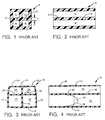
- Figs. 1 and 2 show a filter block A having a plurality of walls which define two lower primary conduits B and two upper secondary conduits C.
- the primary and secondary conduits are separated by an interior wall D having a thickness T and also having metering orifices E therein for flow of backwash fluids from the primary conduits B into the secondary conduits C.
- the blocks A are placed end-to-end in parallel, adjacent rows across a filter bottom and transverse to a flume to define underdrain laterals.
- the underdrain blocks A have been predominately made from clay or concrete.
- the thickness of the interior wall D in these designs is generally on the order of 5/8 - 1 inch.
- Figs. 3 and 4 of the drawings also show a dual lateral underdrain block 10 according to the prior art.
- Underdrain block 10 has a bottom wall 12, a top wall 14 with two sidewalls 16 extending therebetween.
- a vertical partition 18 is located within underdrain block 10 and extends between bottom wall 12 and top wall 14.
- a horizontal platform 20 extends between sidewalls 16. Partition 18 and platform 20 cooperate to define two lower primary horizontal conduits or "laterals" 22 and two upper secondary horizontal conduits 24.
- Horizontal platform 20 contains a plurality of metering orifices 26 which connect primary conduits 22 with secondary conduits 24.
- Top wall 14 contains a plurality of dispersion orifices 28 which connect the secondary conduits 24 with an overlying bed of granular media (not shown).
- the prior art clay and concrete underdrains have sufficient wall thickness and create enough frictional flow losses so that (a) the velocity within primary conduits B adjacent wall D is not unacceptably high, and (b) the angle of repose of flow velocity when entering orifices E does approach 90 degrees.
- the filter system includes a distributor positioned beneath and supporting the media, and the distributor has a plurality of walls which define a primary horizontal conduit and a secondary horizontal conduit. At least one of the walls contains metering orifices that connect the primary conduit to the secondary conduit.
- the system also includes means for introducing backwash fluid into the primary conduit.
- the improvement comprises at least one baffle positioned within the primary conduit to facilitate uniform flow of backwash fluid from the primary conduit through the metering orifices into the secondary conduit.
- the baffle is preferably located near an inlet for the primary conduit.
- the baffle may comprise a flange which is positioned within the primary conduit normal to a fluid flow direction in the conduit. The flange may be contiguous with at least one of the walls or all of the walls which define the primary conduit.
- the baffle may also comprise at least one post upwardly extending within the primary conduit, with an upper end of the post preferably coterminus with a maximum vertical dimension of the primary conduit.
- the post may have a flow impingement face normal to a fluid flow direction in the primary conduit, and further preferred embodiments may include both flanges and posts.
- Another embodiment of the invention includes a tubular insert positioned within at least one metering orifice to facilitate flow of backwash fluids from the primary conduit to the secondary conduit.
- the walls in the distributor containing the metering orifices have a thickness, t and the insert has an inner diameter, d and a length, l.
- the invention contemplates that the length, l of the insert, is greater than the thickness, t of the wall, with the length of the insert equal to or greater than the inside diameter, d of the insert.
- All three aspects of the invention may be utilized to form a complete underdrain system wherein a combination of flanges and posts are positioned at various locations in the primary conduits and inserts are placed in metering orifices to optimize headloss and maldistribution for a particular system design. It is expected that such combinations will be particularly applicable to systems wherein the primary conduits extend to upwards of 5-50 feet in length from flume to filter sidewall.
- Figs. 5-10 show three embodiments of a dual lateral underdrain block 10 according to the present invention.
- Figs. 7-8 show a first embodiment of the invention wherein a flange 30 is positioned within each primary conduit 22 of the underdrain block 10 substantially normal to the longitudinal axis of the primary conduit.
- a flange is preferably located near an inlet 32 for each primary conduit 22 since the inlet is the high energy portion of the conduit.
- the flange 30 is contiguous with portions of the bottom wall 12, sidewalls 16, partition 18 and platform 20 which define primary conduits 22.
- the flange 30 may simply extend into the primary conduit 22 from one or more of these walls, for example as a fixed flap extending downward into primary conduit 22 from horizontal platform 20.
- the flange 30 essentially functions as a baffle within primary conduits 22 to convert velocity energy into head energy, as discussed below.
- the flange may be conveniently molded with the entire underdrain block 10, or with particular pieces thereof, and various flange arrangements may be more suitable for a particular underdrain design. It is anticipated that one flange 30 per four foot underdrain block 10 will be the standard arrangement.
- Figs. 9-10 show a second embodiment of the invention wherein two upstanding posts 34 are centrally located within each primary conduit 22 adjacent the inlet 32 for each conduit.
- Each post has a flow impingement face 36 which is normal to the longitudinal axis of the primary conduit 22.
- the posts 34 extend between the bottom wall 12 and the horizontal platform 20, although other arrangements are possible. It is generally preferable that the posts 34 are at least contiguous with the platform 20 so that flow adjacent the platform may be affected.
- posts 34 act as a baffle within conduits 22 to convert velocity energy into head energy. It is anticipated that one set of posts 34 per four foot underdrain block 10 would be the standard arrangement.
- the posts may be molded along with the underdrain blocks 10 or may be installed in a retrofit manner by fusion welding, snap-in or other suitable attachment. It is anticipated that the posts would generally be of solid construction and of rectangular cross-section.
- An alternative arrangement could include one post 34 within each primary conduit 22, each post aligned with the metering orifices 26 to maximize the baffling effect upstream of the orifices.
- Other arrangements more suitable for particular underdrain designs are possible and are intended to be within the scope of the invention.
- the underdrain blocks 10 are placed end-to-end in parallel, adjacent rows across a filter bottom.
- Backwash fluid primarily water and more recently, an air/water mixture
- Backwash fluid is introduced to the primary conduits 22 from a flume.
- areas of lower fluid velocity are created downstream of the flanges, particularly in the "shadow" of the flanges adjacent platform 20. This reduces the horizontal component of flow velocity through the primary conduits 22. Consequently, the angle of repose of flow velocity through orifices 26 tends toward 90 degrees with respect to the longitudinal axis of the primary conduit 22. This insures that backwash fluid flow does not simply slip over the relatively thin platform 20 at the orifices 26, continuing with a predominantly horizontal velocity.
- velocity profile 38 shows the velocity gradient within primary conduit 22 for prior art clay and concrete dual lateral underdrains.
- Velocity profile 40 is representative of plastic underdrain blocks which do not have baffles 30, 34 according to the invention. It will be apparent that a lower mean velocity within primary conduits 22 is achieved by the clay or concrete underdrains. Profile 40 shows that velocity near the platform 20 in prior art plastic underdrains is higher than for clay underdrains. The invention tends to cause profile 40 to approximate profile 38 when flow passes baffles 30, 34. Thus, mean velocity within the primary conduits 22 is lowered, and the backwash fluid, when entering metering orifices 26, will now have a larger vertical velocity component. The angle of repose will tend to approach 90 degrees.
- baffles 30, 34 provide a tapered flow effect within primary conduits 22 despite the fact that metering orifices 26 may all be of the same diameter.
- incoming backwash fluid sees little frictional resistance, especially in plastic underdrains. This promotes flow of the fluids straight back to the far end of the primary lateral before turning upwards to proceed through metering orifices 26. This causes a "choking off” effect with respect to the metering orifices 26 located near the primary conduit inlet 32.
- Each baffle 30, 34 converts velocity energy into head energy as the backwash fluid proceeds down primary conduits 22.
- a larger portion of the backwash fluid enters the orifices 26 which are located near the inlet 32. Backwash fluid flow is therefore more uniform and the tendency of backwash fluid to proceed directly to the far end of the primary conduits 22 is controlled.
- the flanges 30 or posts 34 are solid and are fixedly located within primary conduits 22, such as when they are molded along with the underdrain block 10.
- a solid, fixed construction of the flanges 30 or posts 34 prevents chattering or undue vibration within the underdrain during backwash. Such constructions are also more resistant to deformation or wear under high backwash pressures.
- Figs. 5-6 show a third embodiment of the invention wherein a tubular insert 42 is placed within each metering orifice 26 in horizontal platform 20.
- the tubular inserts have an upstanding body 44 with an insert flange 46 which abuts horizontal platform 20.
- a length, l of the body 44 is greater than a thickness, t of platform 20, and length, l is greater than or equal to the inside diameter, d of the insert 42. It has been found that such dimensions assist in turning flow from the primary conduit 22 into metering orifices 26 so that the angle of repose of flow velocity approaches 90 degrees with respect to horizontal.
- backwash distribution performance of the modern thin-walled, plastic underdrain blocks is greatly improved.
- a combination of one or more of the above three aspects of the invention may be utilized simultaneously to optimize headloss and maldistribution in a particular underdrain system.
- the present invention provides substantial improvement in performance with respect to both prior art clay underdrain blocks and more recent plastic underdrain blocks which have not been equipped with any aspects of the present invention.
- distribution in dual lateral underdrains can be made more uniform at the same or lower headloss when compared to prior plastic underdrain blocks.
- the invention presents these advantages while being simple and practical to mold in plastic.
Landscapes
- Chemical & Material Sciences (AREA)
- Chemical Kinetics & Catalysis (AREA)
- Devices And Processes Conducted In The Presence Of Fluids And Solid Particles (AREA)
- Sewage (AREA)
Applications Claiming Priority (2)
| Application Number | Priority Date | Filing Date | Title |
|---|---|---|---|
| US07/889,176 US5328608A (en) | 1992-05-27 | 1992-05-27 | Mutli-lateral filter underdrain block |
| US889176 | 1992-05-27 |
Publications (2)
| Publication Number | Publication Date |
|---|---|
| EP0572083A2 true EP0572083A2 (de) | 1993-12-01 |
| EP0572083A3 EP0572083A3 (de) | 1994-02-09 |
Family
ID=25394635
Family Applications (1)
| Application Number | Title | Priority Date | Filing Date |
|---|---|---|---|
| EP19930201471 Withdrawn EP0572083A3 (de) | 1992-05-27 | 1993-05-24 | Multilateraler Unterdrainage-Filterblock |
Country Status (4)
| Country | Link |
|---|---|
| US (1) | US5328608A (de) |
| EP (1) | EP0572083A3 (de) |
| JP (1) | JPH0633506A (de) |
| CA (1) | CA2096377A1 (de) |
Cited By (1)
| Publication number | Priority date | Publication date | Assignee | Title |
|---|---|---|---|---|
| CN110913969A (zh) * | 2017-05-16 | 2020-03-24 | 塞莱默水处理齐利诺普尔有限公司 | 自清洁无灌浆式过滤器暗渠 |
Families Citing this family (24)
| Publication number | Priority date | Publication date | Assignee | Title |
|---|---|---|---|---|
| US5489388A (en) * | 1994-04-12 | 1996-02-06 | The F. B. Leopold Co., Inc. | Apparatus and method for improving gas backwash in lateral underdrains |
| US5792359A (en) * | 1996-07-08 | 1998-08-11 | U.S. Filter Corporation | Sealing shoe for celless travelling bridge filter |
| US6312611B1 (en) | 1996-07-31 | 2001-11-06 | The F.B. Leopold Co., Inc. | Apparatus for distributing gas and liquid during concurrent gas/liquid backwash in filter underdrain flumes |
| CA2262626C (en) * | 1996-07-31 | 2005-07-26 | The F.B. Leopold Co., Inc. | Apparatus for distributing gas and liquid during concurrent gas/liquid backwash in flat bottom flumes |
| US6740237B1 (en) | 1997-09-22 | 2004-05-25 | Rg Delaware, Inc. | Low profile extruded underdrain |
| US6143188A (en) * | 1998-12-22 | 2000-11-07 | Tetra Process Technologies | Underdrain block for filter media system |
| KR200186200Y1 (ko) * | 2000-01-10 | 2000-06-15 | 주식회사도화종합기술공사 | 하부집수장치용 유공블럭 |
| US6569327B2 (en) * | 2001-01-23 | 2003-05-27 | Rg Delaware, Inc. | Apparatus for directing fluids through a filter system |
| US7063787B2 (en) | 2001-06-06 | 2006-06-20 | Usfilter Corporation | Filter media retaining cap and hold down grid |
| US8052871B2 (en) * | 2001-09-10 | 2011-11-08 | Rg Delaware, Inc. | Underdrain system |
| US6991726B2 (en) * | 2002-07-01 | 2006-01-31 | Usfilter Corporation | Filter having a media retaining plate |
| US6830684B2 (en) * | 2002-07-10 | 2004-12-14 | U.S. Filter Corporation | Integrated liquid and gas distribution device for underdrain block laterals |
| USD519601S1 (en) | 2004-09-17 | 2006-04-25 | Rg Delaware, Inc. | Underdrain |
| BRPI0612927A2 (pt) * | 2005-05-17 | 2012-10-02 | Leopold Co Inc F B | aparelho e método para a distribuição de gás e de lìquido durante a contra-lavagem nos filtros das calhas inferiores de escoamento usando uma separação dupla |
| CN100431656C (zh) * | 2006-02-17 | 2008-11-12 | 叶善园 | 筛网式复合型滤板 |
| US8070946B2 (en) | 2007-09-14 | 2011-12-06 | Rg Delaware, Inc. | Underdrain for a filter system for filtering water or wastewater and a method of washing the filter system |
| GB0818511D0 (en) * | 2008-10-09 | 2008-11-19 | Sev Trent Services Ltd | Water filtration apparatus |
| WO2011041513A2 (en) * | 2009-09-30 | 2011-04-07 | Itt Water & Wastewater Leopold, Inc. | Clog resistant media retainer assembly |
| US9072989B2 (en) | 2012-05-21 | 2015-07-07 | Roberts Marketing De, Inc. | Underdrain for a filter system for filtering water or wastewater |
| CA2901279C (en) | 2013-02-15 | 2021-11-09 | Fabrice Jean Alphonse COURAGEOT | Underdrain assembly |
| KR200483375Y1 (ko) * | 2014-12-30 | 2017-05-08 | 황주연 | 지표면수 배수용 투수틀 |
| US10913014B2 (en) | 2015-03-05 | 2021-02-09 | Xylem Water Solutions Zelienople Llc | Multiple rate filter underdrain lateral gas metering plate |
| US10143944B2 (en) | 2016-05-04 | 2018-12-04 | Ovivo Inc. | Filter underdrain with internal air scour laterals |
| US12246271B2 (en) * | 2023-04-04 | 2025-03-11 | De Nora Water Technologies, LLC | Media retention plate for a block underdrain system |
Family Cites Families (24)
| Publication number | Priority date | Publication date | Assignee | Title |
|---|---|---|---|---|
| US477727A (en) * | 1892-06-28 | Filtering apparatus | ||
| US417405A (en) * | 1889-12-17 | Barton h | ||
| US308575A (en) * | 1884-11-25 | Filter | ||
| US727230A (en) * | 1903-02-20 | 1903-05-05 | Frank G Underwood | Leaching-tank filter. |
| US1668205A (en) * | 1924-04-04 | 1928-05-01 | Permutit Co | Strainer head for filtering purposes |
| US1572398A (en) * | 1924-05-12 | 1926-02-09 | Frederick B Leopold | Filtering apparatus |
| US1788383A (en) * | 1925-06-26 | 1931-01-13 | Delery Edna Fuselier | Fluid filter and the like |
| US2378239A (en) * | 1942-12-05 | 1945-06-12 | Leopold Co Inc F B | Filter bottom |
| US2874844A (en) * | 1955-04-07 | 1959-02-24 | Edwin F Wanner | Filter beds and tile |
| US3110667A (en) * | 1959-10-16 | 1963-11-12 | Leopold Co Inc F B | Filter bottom |
| US3512649A (en) * | 1966-03-15 | 1970-05-19 | Rostislav Nebolsine | Ultra-rate water filtration apparatus |
| US3468422A (en) * | 1967-02-03 | 1969-09-23 | Chicago Bridge & Iron Co | Ceramic filter bottom directly supporting media |
| US4065391A (en) * | 1975-09-08 | 1977-12-27 | Sybron Corporation | Fluid distributor |
| US4118322A (en) * | 1976-05-17 | 1978-10-03 | Hydrotechnic Corporation | Filtering apparatus for liquids |
| JPS5635219Y2 (de) * | 1977-08-12 | 1981-08-19 | ||
| US4202774A (en) * | 1978-05-24 | 1980-05-13 | Dorr-Oliver Incorporated | Flow distributor for fluid bed biological reactor |
| JPS5520644A (en) * | 1978-07-31 | 1980-02-14 | Hitachi Metals Ltd | Filtering vessel |
| US4619765A (en) * | 1984-10-10 | 1986-10-28 | Roberts Filter Manufacturing Company | Filter bottom construction |
| US4707257A (en) * | 1986-05-29 | 1987-11-17 | The Graver Company | Air/water distributor underdrain |
| FR2625915B1 (fr) * | 1988-01-15 | 1990-05-25 | Degremont | Procede pour la fabrication de planchers pour filtres, et planchers ainsi realises |
| US5019259A (en) * | 1989-06-15 | 1991-05-28 | Hambley John B | Filter underdrain apparatus with partitioned distributor conduits |
| US5068034A (en) * | 1990-05-03 | 1991-11-26 | Unilift Corporation | Purification underdrain with means to compensate for flow and pressure differences between laterals |
| US5108627A (en) * | 1991-02-01 | 1992-04-28 | F.B. Leopold Company, Inc. | Filter underdrain block |
| US5087362A (en) * | 1991-07-26 | 1992-02-11 | F.B. Leopold Company, Inc. | Flume distribution system with removable block |
-
1992
- 1992-05-27 US US07/889,176 patent/US5328608A/en not_active Expired - Lifetime
-
1993
- 1993-05-17 CA CA002096377A patent/CA2096377A1/en not_active Abandoned
- 1993-05-24 EP EP19930201471 patent/EP0572083A3/de not_active Withdrawn
- 1993-05-24 JP JP5142544A patent/JPH0633506A/ja active Pending
Cited By (1)
| Publication number | Priority date | Publication date | Assignee | Title |
|---|---|---|---|---|
| CN110913969A (zh) * | 2017-05-16 | 2020-03-24 | 塞莱默水处理齐利诺普尔有限公司 | 自清洁无灌浆式过滤器暗渠 |
Also Published As
| Publication number | Publication date |
|---|---|
| US5328608A (en) | 1994-07-12 |
| JPH0633506A (ja) | 1994-02-08 |
| CA2096377A1 (en) | 1993-11-28 |
| EP0572083A3 (de) | 1994-02-09 |
Similar Documents
| Publication | Publication Date | Title |
|---|---|---|
| US5328608A (en) | Mutli-lateral filter underdrain block | |
| US5108627A (en) | Filter underdrain block | |
| US5269920A (en) | Cap system for underdrains in gravity filters | |
| JP2670737B2 (ja) | 濾材の排水および逆洗装置ならびに通風管ブロック | |
| EP0582007B1 (de) | Vorrichtung zur gleichmässigen Verteilung von Gas und/oder Flüssigkeit in einem seitlichen Unterdrainagesystem | |
| EP0523293A1 (de) | Filtration von Flüssigkeiten | |
| EP0524780A1 (de) | Kanalverteilungssystem mit abnehmbarem Block | |
| US5534202A (en) | Air grid for underdrains and similar systems | |
| US6143188A (en) | Underdrain block for filter media system | |
| CA1078304A (en) | Fluid distributor | |
| US6790357B2 (en) | Media bed support grid | |
| KR102448163B1 (ko) | 터널형태의 낮은 구조를 갖는 유공블록형 하부집수장치 | |
| US4608168A (en) | Distribution filter nozzles and filters incorporating same | |
| US7922903B2 (en) | System and method for uniformly distributing a fluid through a filter bed in a filter | |
| US7736506B2 (en) | System and method for uniformly distributing a fluid through a filter bed in a filter | |
| US5176827A (en) | Filter underdrain with means to increase gas flow during simultaneous gas/liquid backwashing | |
| KR102957919B1 (ko) | 패턴 구조의 슬릿형 오리피스를 갖는 하부집수장치형 여과시스템 | |
| US20030230542A1 (en) | Flow splitting weir | |
| US7758750B2 (en) | Flume for a filter system including at least one filter having a filter bed that is periodically washed with liquid, gas or a combination thereof | |
| JPH044806Y2 (de) | ||
| JP2003517366A (ja) | フィルタ | |
| GB2264653A (en) | Filter bed | |
| CA2046834A1 (en) | Underdrain for liquid purification systems | |
| GB1604509A (en) | Filters for liquids |
Legal Events
| Date | Code | Title | Description |
|---|---|---|---|
| PUAI | Public reference made under article 153(3) epc to a published international application that has entered the european phase |
Free format text: ORIGINAL CODE: 0009012 |
|
| AK | Designated contracting states |
Kind code of ref document: A2 Designated state(s): AT CH DE FR GB LI NL |
|
| PUAL | Search report despatched |
Free format text: ORIGINAL CODE: 0009013 |
|
| AK | Designated contracting states |
Kind code of ref document: A3 Designated state(s): AT CH DE FR GB LI NL |
|
| STAA | Information on the status of an ep patent application or granted ep patent |
Free format text: STATUS: THE APPLICATION IS DEEMED TO BE WITHDRAWN |
|
| 18D | Application deemed to be withdrawn |
Effective date: 19940810 |