EP0571767B1 - Image-forming apparatus - Google Patents
Image-forming apparatus Download PDFInfo
- Publication number
- EP0571767B1 EP0571767B1 EP93106757A EP93106757A EP0571767B1 EP 0571767 B1 EP0571767 B1 EP 0571767B1 EP 93106757 A EP93106757 A EP 93106757A EP 93106757 A EP93106757 A EP 93106757A EP 0571767 B1 EP0571767 B1 EP 0571767B1
- Authority
- EP
- European Patent Office
- Prior art keywords
- developer
- developer container
- cover
- image
- container
- Prior art date
- Legal status (The legal status is an assumption and is not a legal conclusion. Google has not performed a legal analysis and makes no representation as to the accuracy of the status listed.)
- Expired - Lifetime
Links
Images


Classifications
-
- G—PHYSICS
- G03—PHOTOGRAPHY; CINEMATOGRAPHY; ANALOGOUS TECHNIQUES USING WAVES OTHER THAN OPTICAL WAVES; ELECTROGRAPHY; HOLOGRAPHY
- G03G—ELECTROGRAPHY; ELECTROPHOTOGRAPHY; MAGNETOGRAPHY
- G03G15/00—Apparatus for electrographic processes using a charge pattern
- G03G15/06—Apparatus for electrographic processes using a charge pattern for developing
- G03G15/08—Apparatus for electrographic processes using a charge pattern for developing using a solid developer, e.g. powder developer
- G03G15/0822—Arrangements for preparing, mixing, supplying or dispensing developer
- G03G15/0877—Arrangements for metering and dispensing developer from a developer cartridge into the development unit
- G03G15/0881—Sealing of developer cartridges
- G03G15/0886—Sealing of developer cartridges by mechanical means, e.g. shutter, plug
-
- G—PHYSICS
- G03—PHOTOGRAPHY; CINEMATOGRAPHY; ANALOGOUS TECHNIQUES USING WAVES OTHER THAN OPTICAL WAVES; ELECTROGRAPHY; HOLOGRAPHY
- G03G—ELECTROGRAPHY; ELECTROPHOTOGRAPHY; MAGNETOGRAPHY
- G03G15/00—Apparatus for electrographic processes using a charge pattern
- G03G15/06—Apparatus for electrographic processes using a charge pattern for developing
- G03G15/08—Apparatus for electrographic processes using a charge pattern for developing using a solid developer, e.g. powder developer
- G03G15/0822—Arrangements for preparing, mixing, supplying or dispensing developer
- G03G15/0848—Arrangements for testing or measuring developer properties or quality, e.g. charge, size, flowability
- G03G15/0849—Detection or control means for the developer concentration
- G03G15/0855—Detection or control means for the developer concentration the concentration being measured by optical means
-
- G—PHYSICS
- G03—PHOTOGRAPHY; CINEMATOGRAPHY; ANALOGOUS TECHNIQUES USING WAVES OTHER THAN OPTICAL WAVES; ELECTROGRAPHY; HOLOGRAPHY
- G03G—ELECTROGRAPHY; ELECTROPHOTOGRAPHY; MAGNETOGRAPHY
- G03G15/00—Apparatus for electrographic processes using a charge pattern
- G03G15/06—Apparatus for electrographic processes using a charge pattern for developing
- G03G15/08—Apparatus for electrographic processes using a charge pattern for developing using a solid developer, e.g. powder developer
- G03G15/0822—Arrangements for preparing, mixing, supplying or dispensing developer
- G03G15/0865—Arrangements for supplying new developer
-
- G—PHYSICS
- G03—PHOTOGRAPHY; CINEMATOGRAPHY; ANALOGOUS TECHNIQUES USING WAVES OTHER THAN OPTICAL WAVES; ELECTROGRAPHY; HOLOGRAPHY
- G03G—ELECTROGRAPHY; ELECTROPHOTOGRAPHY; MAGNETOGRAPHY
- G03G15/00—Apparatus for electrographic processes using a charge pattern
- G03G15/06—Apparatus for electrographic processes using a charge pattern for developing
- G03G15/08—Apparatus for electrographic processes using a charge pattern for developing using a solid developer, e.g. powder developer
- G03G15/0822—Arrangements for preparing, mixing, supplying or dispensing developer
- G03G15/0877—Arrangements for metering and dispensing developer from a developer cartridge into the development unit
- G03G15/0879—Arrangements for metering and dispensing developer from a developer cartridge into the development unit for dispensing developer from a developer cartridge not directly attached to the development unit
Definitions
- the present invention relates to image-forming apparatuses to which a developer is supplied from a developer container such as electrophotographic copying machines and laser printers. Particularly it relates to an image-forming apparatus according to the preamble of claim 1.
- Such an image-forming apparatus is disclosed by the European Patent Application No. 0 261 643.
- the apparatuses described there comprise a developer cartridge which has to be changed by a new refifled cartridge when the inserted cartridge contains not enough developer for the futher processing of the apparatus.
- the apparatuses are provided with a dicrimination unit like a barcode-reader which enables the apparatus only when an appropriated cartridge is inserted or which makes it impossible to insert a cartrige containing a wrong developer.
- the replenishments are generally carried out in the following manner.
- a developer container containing a developer is inserted into a reservoir of developer replenisher of the main body of the apparatus and the cover for the developer reservoir and the cover for the developer container are opened and closed in the inserted state, so that the developer inside the developer container may be replenished to the developer replenisher.
- JP OPI Publication Japanese Patent Publication Open to Public Inspection
- 3-267965/1991 and 3-269461/1991 there are some apparatuses in which it is made impossible to insert any developer container containing different color developer into a developer replenisher of the main apparatus body, except that only a specific developer container can be inserted therein, so that the replenishments can be made only from a developer container containing the same color developer.
- the inserted developer container when inserting a developer container into a developer replenisher, the inserted developer container is discriminated as to whether it is the specified one or not and, only when the inserted developer container is the specified one, can the cover for the developer replenisher and a cover for the specified developer container be opened and closed.
- An image-forming apparatus wherein the developer container containing a developer is inserted into the developer replenisher of a main body of the apparatus and the cover for the developer replenisher and the cover for the developer container are opened and closed in the inserted state, so that the developer inside the developer container can be replenished from the developer replenisher.
- the above-mentioned image-forming apparatus is according to claim 1 characterized in that a discriminating means is provided so as to discriminate whether the inserted developer container is the specified one or not and the cover for the developer replenisher and the cover for the developer container are so constructed as to be opened and closed only when the inserted developer container is the specified one.
- the cover for the developer replenisher and the cover for the developer container may be opened and closed interlockingly in the inserted state.
- the specified developer container may be discriminated by a mechanical or an electrical means operated by inserting the developer container into the developer replenisher and thereby the cover for the developer replenisher and the cover for the developer container can be opened and closed.
- the developer container may be discriminated as to whether it is the specified one or not by a discriminating means applied with a discriminator of the developer container and, when the developer container is discriminated as being the specified one, the controls of the control means are released so that both covers for the developer container and for the developer replenisher can be opened and closed.
- a discriminator is provided to discriminate whether the developer container is the specified one or not and a control means is provided so that, when the developer container is discriminated as being the specified one by the discriminating means provided with the discriminator, both covers for the developer container and the developer replenisher can be opened and closed by releasing the control of the discriminator provided to discriminate whether the developer container is the specified one or not and a control means is provided so that, when the developer container is discriminated as being the specified one by the discriminating means provided with the discriminator, both covers for the developer container and the developer replenisher can be opened and closed by releasing the control.
- a discriminated information is read out of a discrimination information section of the developer container by a sensor provided to the developer replenisher, and thereby the developer container is discriminated, so that the cover for the developer replenisher and the cover for the specified developer container can be opened and closed.
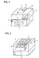
- Fig. 1 is a perspective view of an image-forming apparatus seeing from the front
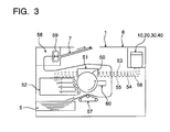
- Fig. 2 is a perspective view of the image-forming apparatus seeing from the back
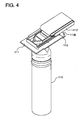
- Fig. 3 is a schematic illustration of the structure of the image-forming apparatus.
- Image-forming apparatus 1 was provided with electric power switch 2 to the left side of the front, operation unit 3 and display 4 to the upper right side of the front and aperture 6 for setting paper-feeding unit 5 containing recording paper to the center of the front, respectively.
- Recorded paper takeout section 7 for taking out recorded paper was also provided to the center of the upper side of image-forming apparatus 1 and developer replenisher 8 for replenishing a developer was further provided to the back side of recorded paper takeout section 7.
- cover 9 for developer replenisher 8 was opened backward, yellow developer reservoir 10, magenta developer reservoir 20, cyan developer reservoir 30 and black developer reservoir 40 could be replenished thereto with the corresponding color developers, respectively.
- Photoreceptor 50 rotatable to the direction of the arrow was provided to the inside of image-forming apparatus 1. First, photoreceptor 50 was uniformly charged by charging-exposure section 51 as it was rotated and next it was then exposed to an optical image subject to a copy development from a digital image information. In the above-mentioned manner, an electrostatic latent image corresponding to the development can be formed on photoreceptor 50.
- the resulting electrostatic latent image was developed in yellow, magenta, cyan and black at developing section 52, so that a toner image could be formed.
- yellow developer reservoir 10, magenta developer reservoir 20, cyan developer reservoir 30 and black developer reservoir 40 were connected through replenishing pipes 53 ⁇ 56, so that the same color developers could be replenished from developer replenisher 8 of the main apparatus body, respectively.
- the resulting toner image is transferred to a recording paper under the function of transfer-charging unit 57.
- the recording paper sheets were fed one after another out of paper feeding unit 5 and the toner image was then transferred under the function of transfer-charging unit 57.
- the recorded paper was separated from photoreceptor 50 and then sent to fixing unit 58, so that toner was fused into the recorded paper, and thereby the image was fixed onto the recorded paper.
- the toner remaining on photoreceptor 50 was cleaned up by cleaning unit 60 and photoreceptor 50 was ready to be used again in the above-mentioned image-forming process.
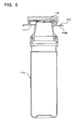
- Fig. 4 is a perspective view of a yellow developer container
- Fig. 4 is a cross-sectional view of the yellow developer container
- Fig. 6 is a perspective view of a part of the yellow developer container.
- yellow developer container 110 a developer was contained.
- slidable cover 112 was provided to supply section 111 of the above-mentioned yellow developer container 110.
- discriminating section 113 corresponding to the color of a developer was provided.
- the above-mentioned discriminating section 113 was comprised of plate portion 113b having notched portion 113a provided to the end of supply section 111.
- Fig. 7 is a perspective view of a part of a magenta developer container.
- slidable cover 122 was similarly provided.
- discriminator 123 corresponding to the color of a developer was also provided.
- plate portion 123b constituting the above-mentioned discriminator 123 notched portion 123a was provided to a position different from the above-mentioned position.
- Fig. 8 is a perspective view of a part of a cyan developer container.
- slidable cover 132 was similarly provided.
- discriminator 133 corresponding to the color of a developer was also provided.
- plate portion 133b constituting discriminator 133 notched portion 133a was provided to a position different from the above-mentioned position.
- Fig. 9 is a perspective view of a part of a black developer container.
- slidable cover 142 was similarly provided.
- discriminator 143 corresponding to the color of a developer was also provided.
- plate portion 143b constituting the above-mentioned discriminator 143 notched portion 143a was further provided to a position different from the above-mentioned position.
- yellow developer container 110, magenta developer container 120, cyan developer container 130 and black developer container 140 were as same as in the constitution, only except that the constitution of discriminators 113, 123, 133 and 143 each corresponding to the colors of developers.
- the production costs were reduced by making the constitution be in common.
- Fig. 10 is a top-plan view of the developer replenisher of an image-forming apparatus.
- Fig. 11 is a perspective view showing the insertion of a developer container into the developer replenisher of an image-forming apparatus.
- Fig. 12 is a cross-sectional view showing the state where the same developer container was inserted therein.
- Fig. 13 is a cross-sectional view showing the state where a different developer container was inserted therein.
- developer replenisher 8 was arranged with yellow, magenta, cyan and black developer reservoirs 10, 20, 30, 40, respectively.
- Developer supply sections 111, 121, 131, 141 of yellow, magenta, cyan and black developer containers 110, 120, 130, 140 were so provided as to be inserted into replenishing apertures 11, 21, 31, 41 of developer reservoirs 10, 20, 30, 40, respectively.
- Covers 12, 22, 32, 42 were so provided as to be slidable to replenishing apertures 11, 21, 31, 41, respectively.
- the covers 12, 22, 32, 42 were provided with knobs 13, 23, 33, 43, respectively. Covers 12, 22, 32, 42 were opened and closed by operating knobs 13, 23, 33, 43 by hand, respectively.
- Covers 12, 22, 32, 42 were usually arranged to cover replenishing apertures 11, 21, 31, 41 so as to prevent incoming dust from replenishing apertures 11, 21, 31, 41 or to prevent any other developers from mixing-in when replenishing a developer.
- covers 12, 22, 32, 42 were coupled interlockwise to covers 112, 122, 132, 142 of developer supply sections 111, 121, 131, 141 to be opened and closed, respectively.
- Control means A was so constituted as to release the control when inserting the supply sections of developer containers into replenishing apertures 11, 21, 31, 41 and to make covers 12, 22, 32, 42 slidable.
- stopper pins 17, 27, 37, 47 were provided, respectively. Stopper pins 17, 27, 37, 47 were so positioned as to face to notches 113a, 123a, 133a, 143a of discriminators 113, 123, 133, 143 corresponding to the colors of developers contained in yellow, magenta, cyan and black developer containers 110, 120, 130, 140, respectively.
- Stopper pins 17, 27, 37, 47 were provided with heads 17a, 27a, 37a, 47a and collars 17b, 27b, 37b, 47b, respectively.
- Springs 18, 28, 38, 48 were provided between heads 17a, 27a, 37a, 47a and the upper surfaces of replenishing apertures 11, 21, 31, 41, so that stopper pins 17, 27, 37, 47 could be elastically energized upward constantly.
- stopper pins 17, 27, 37, 47 were not pushed downward against springs 18 ⁇ 48, because stopper pins 17, 27, 37, 47 and notches 113a, 123a, 133a, 143a of yellow, magenta, cyan and black developer containers 110, 120, 130, 140 were so positioned as to face to each other, respectively. Therefore, stopper walls 12b, 22b, 32b, 42b of covers 12 ⁇ 42 were not hit against stopper pins 17, 27, 37, 47, so that covers 12, 22, 32, 42 could be slidable, respectively.
- stopper pins 17, 27, 37, 47 were pushed downward against the elasticity of springs 18 ⁇ 48 in plate positions 113b, 123b, 133b, 143b of discriminators 113, 123, 133, 143 corresponding to the colors of developers, respectively. Therefore, stopper walls 12b, 22b, 32b, 42b of covers 12 ⁇ 42 were so positioned as to be hit against the pins, so that the sliding of covers 12, 22, 32, 42 could be controlled.
- discriminating means B for discriminating whether the inserted developer container was specific one or not was constituted. Accordingly, the covers for developer replenishers and the covers for specific developer containers could be opened and closed only when the inserted developer containers were specific ones, respectively.
- Discriminating means B shall not be limited to the above-described discriminating means B, but shall include any one of those, provided that a developer container is allowed to be inserted into a developer replenisher and that the inserted developer container can be discriminated whether it is specific one or not.
- replenishing apertures 11, 21, 31, 41 Each of the upper surface of replenishing apertures 11, 21, 31, 41 was provided with contact piece 19a constantly coming into contact with stopper pins 17, 27, 37, 47.
- the inside of replenishing apertures 11, 21, 31, 41 were provided with contact pieces 19b, 29b, 39b, 49b to come into contacted with collars 17b, 27b, 37b, 47b of the stopper pins when stopper pins 17, 27, 37, 47 were pushed to be moved, respectively.
- contact pieces 19a, 29a, 39a, 49a were electrified to contact pieces 19b, 29b, 39b, 49b, respectively, an erroneous insertion was displayed on display 4.
- supply sections 111, 121, 131, 141 of yellow, magenta, cyan and black developer containers 110, 120, 130, 140 were inserted into replenishing apertures 11, 21, 31, 41 of yellow, magenta, cyan and black developer reservoirs 10, 20, 30, 40, respectively.
- a developer container containing any different developer was erroneously inserted, such an erroneous insertion can easily be confirmed visually, because a stopper pin was pushed to be moved by the discriminator of the corresponding developer container.
- the control of the cover for the developer replenishers which was controlled by control means A, was so released as to be slidable.
- the sliding of the covers for the developer reservoirs were controlled. Therefore, the replenishments of any different color developers were prevented.
- Yellow, magenta, cyan and black developer reservoirs 10, 20, 30, 40 were each made of plastics and built into one body.
- the reservoirs were allowed to be processed by changing the positions of the stopper pins later on, so that the molding dies could be used in common so as to reduce the production costs.
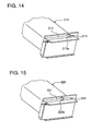
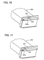
- Fig. 14 is a perspective view of a part of a yellow developer container.
- Fig. 15 is a perspective view of a part of a magenta developer container.
- Fig. 16 is a perspective view of a part of a cyan developer container.
- Fig. 17 is a perspective view of a part of a black developer container.
- discriminators 213, 223, 233, 243 corresponding to the colors of developers were provided, respectively.
- These discriminators 213, 223, 233, 243 were formed of protrusions 213c, 223c, 233c and 243c each formed to the different positions, respectively.
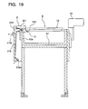
- Fig. 18 is a top-plan view of the developer replenisher of the main body of the image-forming apparatus.
- Fig. 19 is a cross-sectional view of the same developer container in the inserted state.
- Fig. 20 is a cross-sectional view of a different developer container in the inserted state.
- boxes 314, 324, 334, 344 elongated to the sliding direction were provided, respectively.
- locking members 315, 325, 335, 345 were so provided as to be movable to the direction of covers 12, 22, 32, 42, at the position corresponding to the colors of developers, respectively.
- the locking members 315, 325, 335, 345 were energized by leaf-springs 316, 326, 336, 346 so as to be coupled to hollows 12a, 22a, 32a, 42a formed inside covers 12, 22, 32, 42, respectively.
- the locking members were provided to the positions corresponding to the colors of developers and were then coupled to covers 12, 22, 32, 42 so as to control the sliding.
- the controls were released by inserting the supply section of a developer container containing the same color developer into replenishing apertures 11, 21, 31, 41, so that covers 12, 22, 32, 42 could be slidable.
- slits 311, 321, 331, 341 were so provided as to be in the positions corresponding to locking members 315, 325, 335, 345, respectively.
- the movements of locking members 315, 325, 335, 345 can easily be confirmed visually through the slits 311, 321, 331, 341, respectively.
- contact pieces 312a, 322a, 332a, 342a were provided, respectively.
- contact pieces 312b, 322b, 332b, 342b were provided, respectively.
- contact piece 312a and contact piece 312b were electrified through leaf-springs 316, 326, 336, 346, so that a normal insertion could be displayed on display 4, respectively.
- the developer supply sections of yellow, magenta, cyan and black developer containers 210, 220, 230, 240 were to be inserted into developer replenishing apertures 11, 21, 31, 41 of the developer reservoirs.
- the control was released by operating locking member provided to the position corresponding to the color of the developer, so that covers 12, 22, 32, 42 could become slidable and the same color developer was replenished to the corresponding developer reservoir.
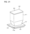
- Fig. 21 is a perspective view showing the external appearance of a developer container.
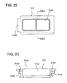
- Fig. 22 is a top-plan view showing the configuration of the flange of a developer container.
- Fig. 23 is a cross-sectional view taken along the line XXIII - XXIII of Fig. 22.
- Fig. 24 is a cross-sectional view showing the structure of the developer replenisher that was provided to the main body of an apparatus, as a developer container was inserted therein.
- Fig. 25 is a schematic illustration showing the structure of a developing section arranged to an image-forming apparatus.
- developing section 502 arranged to image-forming apparatus 501 was provided with developer replenisher 504 that was provided with replenishing aperture 503 to insert developer container 510 into the right upper part of main developing section body 502a.
- a prescribed amount of developer was supplied by the inserted developer container 510 into developing section 502. Then, the developer was transported through a fixed transport path provided into developing section 502.
- the developer was supplied, through developing sleeve-roller 505 provided to the left end of developing section 502, onto an electrostatic latent image formed on the circumferential surface of photoreceptor 506 adjacent to developing sleeve-roller 505 with a fixed space therebetween, so that a developed toner image could be formed on the circumferential surface of photoreceptor 506.
- a developer in developing section 502 was consumed on occasion in every series of developments. Therefore, after completing a certain frequency of developments, it was so arranged as to insert another separately prepared developer container 510 therein and to replenish a developer into developing section 502, so that every uniform toner image could constantly be obtained thereby.
- the above-described image-forming apparatus was provided with an electric means for discriminating a specific developer container in the state where developer containers were inserted into developer replenishers of the main body of the apparatus and with a means capable of opening and closing the covers for a developer replenisher and a specific developer container.
- a discrimination information section was provided to each developer container and, at the same time, a sensor for reading a discrimination information given from the discrimination information section was also provided to each developer replenisher of the main apparatus body, so that the covers for the developer replenishers of the main apparatus body and for the developer containers could be opened and closed by the discrimination made by the sensor.
- the apparatus was structures as follows.
- developer container 510 was comprised of vessel 511 for containing a developer, flange 512 formed into a body with vessel 511, cover 513 slidably attached to flange 512, top cover 514 for covering the upper surface of vessel 511, and bar-code 515 for discriminating a developer to be contained, the color of the developer, the destination and so forth.
- Each of vessel 511, flange 512, cover 513 and top cover 514 was molded of plastics and the configuration thereof was in common, regardless of the colors of developers and the destination thereof.
- flange 512 was comprised of aperture 512c having the central portion substantially bored in the rectangular form, top surface 512b shown in Fig. 23, long groove 512d provided to the outer circumference of aperture 512c to join vessel 511, and U-shaped guide grooves 512e that was made slidable by fitting sliding covers 513 in both sides of the flange in the longitudinal direction.
- Protruded piece 512a was provided to the position where upper surface 512b was extended, to the longitudinal direction, from the end of the left side of flange 512.
- Bar-code 515 was made ready to be attached to the surface opposite to a developer replenisher, after developer container 510 had contained a developer and prepared.
- Cover 513 which was to be attached to the lower surface of flange 512, was made of a flat-plate member provided with ribs (not shown) to both side ends in the longitudinal direction to fit in sliding groove 512e of flange 512. Also, cover 513 had a size large enough at least to cover the whole area of aperture 512c of flange 512. Further, when cover 513 was slid to a fixed position where aperture 512c was covered, cover 513 was so set as not to be shifted easily by clicking each other.
- vessel 511 was partly assembled by joining vessel 511 to flange 512, it was kept in stock and reserved. At this time, cover 513 was allowed to be fitted in, and it was also allowed to mold vessel 511 and flange 512 together into one body. Then, cover 513 was attached to vessel 511 attached with flange 512. A prescribed amount of a developer was contained in vessel 511 having aperture 512c closed by cover 513. After fitting the aforementioned top cover 514 into one body, bar-code 515 designating the color of a developer and the destination was attached to the prescribed position of protruded piece 512a of flange 512. Thereby, discriminated developer container 510 could be prepared. Further, a suitable protect-cover (not shown) was so fitted in to cover both cover 513 and flange 512 so that a developer contained in developer container 510 could not be spilt carelessly.
- flange 512 was in common regardless of the colors of developers and the destinations and the dies for molding were also commonly used. It was, therefore, very convenient for improving the efficiency.
- Developer container 510 prepared in the above-described manner was attached to developer replenisher 503 arranged to developing section 502 to be supplied with a developer in an amount corresponding to the consumption of the developer.
- developer replenisher 503 was provided, with rectangular-shaped replenishing aperture 503b, to the neighborhood of the upper center of developer reservoir 503a.
- cover 520 for opening and closing the replenishing aperture 503b was slidably attached in the direction of the arrow.
- bent portion 520a erected at right angles was provided to the left end of cover 520 to couple it to the left end of cover 513 when developer container 510 was inserted in.
- cover 520 Under the right end of cover 520 so positioned as to cover replenishing aperture 503b, there provided with hook 523 that was suspended on the frame of developer reservoir 503a to be rotatable around fulcrum axis 523b.
- the hook 523 was provided with one end to the left end portion and the other end thereof was elastically energized counterclockwise constantly by spring 524 fixed to the frame of developer reservoir 503a.
- Cover 520 was hooked by coupling claw 523a provided to the right end of hook 523 to the right end surface of cover 520.
- knob 521 To the right upper end surface of cover 520, knob 521 was fitted up into one body. The upper part of knob 521 was protruded upward to cover 522 covering the upper part of developer reservoir 503a.
- Knob 521 was so arranged as to be movable together with cover 520 to the direction of the arrow by operating it by hand.
- cover 522 To cover 522, long hole 522a was so provided as not to interfere the operation range of knob 521.
- solenoid 525 In the lower portion opposite to hook 523, solenoid 525 was fitted to the frame of developer reservoir 503a. When electrifying solenoid 525 to be magnetically excited, hook 523 was rotated clockwise against spring 524, so that it released from the coupling to cover 520.
- sensor 516 for reading bar-code 515 was provided oppositely to bar-code 515 when developer container 510 was attached to replenishing aperture 503b.
- sensor 516 was covered by sensor-cover 517 as indicated by two-dot chain line.
- developer replenisher 503 structured as above, after sensor-cover 517 thereof was opened as indicated by the solid line in Fig. 24 to expose the upper part of sensor 516 and designated developer container 510 was then inserted in through flange 512 and when developer container 510 was so detected as to be adaptable upon reading bar-code 515 by sensor 516 set to the fixed position shown in the drawing, solenoid 525 was electrified to be magnetically excited and, by the magnetic force of solenoid 525, hook 523 was rotated clockwise and the coupling to cover 520 was released free.
- cover 513 of developer container 510 which was coupling to knob 521, was also moved together with cover 520, so that aperture 512c of flange 512 and replenishing aperture 503b of developer replenisher 503 were opened. Thereby, a developer contained in developer container 510 was dropped into developer replenisher 503a to be supplied.
- cover 520 was returned together with cover 513 to a fixed position covering replenishing aperture 503b. At that time, cover 520 was hooked again by hook 523.
- bar-code 515 was attached to developer container 510 so that a discrimination could be made.
- the scope of the invention shall also include not only the above-described bar-code 515, but also a means in which a detection was made by attaching separate magnetic tapes for detecting every color of developers and every destination so that any erroneous insertion could be prevented in the above-described method.
- Each of all the members for structuring a developer container could have the same configurations in common, because separate bar-codes or magnetic tapes were attached to developer containers to detect the colors of developer and destinations. Therefore, the warehousing controls and assembling processes of the assembled parts of each member could be very simplified and the efficiency thereof could also be remarkably improved. It was the matter of course to completely avoid the erroneous insertion of developer containers into developer replenishers.
- the cover for a developer replenisher and the cover for a specific developer container is opened and closed when the developer container is inserted into the developer replenisher and the specific developer container is inserted into the developer replenisher. It is, therefore, possible to solve the following inconvenience; as in the conventional image-forming apparatuses, a portion of the developer container containing a different color developer is inserted askew into the developer replenisher and the cover thereof is opened by coupling it to the cover for the developer container, so that the different color developer is replenished from the developer replenisher or the developer is made adhered to the surroundings of the developer replenisher. Besides, every developer container is inserted once into the developer replenishers and, therefore, the developer containers cannot be damaged even if a developer container containing a different color developer is tried to forcibly insert in.
- both covers for the developer replenisher and for the specific developer container are opened and closed interlockwise each other. It is, therefore, possible to prevent the cover for the developer container and the surroundings thereof from making adhered thereto with a developer spouted up from the developer replenisher side.
- a specific developer container is discriminated by a mechanical means operated by inserting the developer container into a developer replenisher and the cover for the developer replenisher and the cover for the specific developer container are opened and closed thereby. It is, therefore, possible to prevent any erroneous insertion by discriminating the developer container in a simple structure.
- a developer container is discriminated whether it is specific one or not by a discriminating means applied with the discriminator of the developer container and, when the developer container is discriminated to be specific one, a control means is released and, both covers for the developer container and the developer replenisher can be opened and closed. It is, therefore, possible to prevent any erroneous insertion of the developer container in a simple structure and to prevent any developer leakage from the developer replenisher, because the cover for the developer replenisher cannot be opened and closed when the developer is not replenished or a developer container is erroneously inserted in.
- a specific developer container is discriminated by an electric means operable in the state where the developer container is inserted into a developer replenisher and the cover for the developer replenisher and the cover for the developer container are opened and closed thereby. It is, therefore, possible to replenish a developer after the developer container can automatically be discriminated when inserting the developer container into the developer replenisher.
- a discrimination information is read from the discrimination section of a developer container by a sensor provide to a developer replenisher and the cover for the developer replenisher and the cover for a specific developer container can be opened and closed upon discriminating the developer container. It is, therefore, possible to discriminate the developer container in a simple structure and then to replenish a developer.
Description
- The present invention relates to image-forming apparatuses to which a developer is supplied from a developer container such as electrophotographic copying machines and laser printers. Particularly it relates to an image-forming apparatus according to the preamble of
claim 1. - Such an image-forming apparatus is disclosed by the European Patent Application No. 0 261 643. The apparatuses described there comprise a developer cartridge which has to be changed by a new refifled cartridge when the inserted cartridge contains not enough developer for the futher processing of the apparatus. To prevent the user from inserting a wrong cartridge, for example containing a developer of a different color, the apparatuses are provided with a dicrimination unit like a barcode-reader which enables the apparatus only when an appropriated cartridge is inserted or which makes it impossible to insert a cartrige containing a wrong developer.
- In recent years, however, compact sized image-forming apparatuses for personal use have been popularized and the users' application has been widened, so that not only commercial users but only private users want to get multicolor-images supercomposed with different colors. Therefore image-forming apparatuses and espacially multicolor-imageforming apparatuses were made smaller and more compact and the use of developer cartridges was not more advantegeous or possible. Consequently modern image-forming apparatuses are provided with at least one developer reservoir which is to be replenished when there is not enough developer inside the apparatus.
- The replenishments are generally carried out in the following manner. A developer container containing a developer is inserted into a reservoir of developer replenisher of the main body of the apparatus and the cover for the developer reservoir and the cover for the developer container are opened and closed in the inserted state, so that the developer inside the developer container may be replenished to the developer replenisher.
- In such an image-forming apparatus as mentioned above, however, when trying to replenish a certain color developer from a developer container containing the same color developer into a developing section and if erroneously replenishing some different color developer from a developer container containing the different color developer, there may be a possibility of making the apparatus unusable at all until the developing section is overhauled to be cleaned up.
- Therefore, as disclosed each in Japanese Patent Publication Open to Public Inspection (hereinafter abbreviated to JP OPI Publication) Nos. 3-267965/1991 and 3-269461/1991, there are some apparatuses in which it is made impossible to insert any developer container containing different color developer into a developer replenisher of the main apparatus body, except that only a specific developer container can be inserted therein, so that the replenishments can be made only from a developer container containing the same color developer.
- Even in an apparatus in which a specific developer container only can be inserted into the developer replenisher of the main apparatus body and if even a portion of the developer container containing a different color developer is inserted askew into the developer replenisher of the main apparatus body, there may be some instances where the cover for the developer container may be opened by coupling it to the developer replenisher of the main apparatus body, in the above-mentioned state. Therefore, a different kind of developers may sometimes be erroneously replenished from a developer replenisher of the main apparatus body or a trouble may be produced to make the developer adhere to the surroundings of the developer replenisher of the main apparatus body.
- When a replenishment is carried out by an average user, he cannot discriminate whether the method of inserting a developer container is wrong or not and whether a wrong developer container is inserted or not. Therefore, not only it takes a long time to replenish a developer, but also there is a possibility of damaging the developer container because he tries to forcibly insert the developer container containing a different kind of developer.
- It is therefore object of the present invention to provide an simple-structured and easy-handling image-forming apparatus of the type mentioned at the beginning which is capable of being replenished with at least one type of developer and which is capable of preventing any replenishments safely without damaging the developer container or damaging or dirtying the apparatus itself.
- This object is achieved by an image-forming apparatus as defind by the features of
claim 1. - In order to solve the above-mentioned problems, when inserting a developer container into a developer replenisher, the inserted developer container is discriminated as to whether it is the specified one or not and, only when the inserted developer container is the specified one, can the cover for the developer replenisher and a cover for the specified developer container be opened and closed.
- An image-forming apparatus wherein the developer container containing a developer is inserted into the developer replenisher of a main body of the apparatus and the cover for the developer replenisher and the cover for the developer container are opened and closed in the inserted state, so that the developer inside the developer container can be replenished from the developer replenisher.
- The above-mentioned image-forming apparatus is according to
claim 1 characterized in that a discriminating means is provided so as to discriminate whether the inserted developer container is the specified one or not and the cover for the developer replenisher and the cover for the developer container are so constructed as to be opened and closed only when the inserted developer container is the specified one. - The cover for the developer replenisher and the cover for the developer container may be opened and closed interlockingly in the inserted state.
- The specified developer container may be discriminated by a mechanical or an electrical means operated by inserting the developer container into the developer replenisher and thereby the cover for the developer replenisher and the cover for the developer container can be opened and closed.
- The developer container may be discriminated as to whether it is the specified one or not by a discriminating means applied with a discriminator of the developer container and, when the developer container is discriminated as being the specified one, the controls of the control means are released so that both covers for the developer container and for the developer replenisher can be opened and closed.
- In the image-forming apparatus according to an embodiment of the invention a discriminator is provided to discriminate whether the developer container is the specified one or not and a control means is provided so that, when the developer container is discriminated as being the specified one by the discriminating means provided with the discriminator, both covers for the developer container and the developer replenisher can be opened and closed by releasing the control of the discriminator provided to discriminate whether the developer container is the specified one or not and a control means is provided so that, when the developer container is discriminated as being the specified one by the discriminating means provided with the discriminator, both covers for the developer container and the developer replenisher can be opened and closed by releasing the control.
- In case of an advantageous embodiment according claim 5 a discriminated information is read out of a discrimination information section of the developer container by a sensor provided to the developer replenisher, and thereby the developer container is discriminated, so that the cover for the developer replenisher and the cover for the specified developer container can be opened and closed.
- Advantageous embodiments are described in the subclaims and further advantages of the Invention are described in the following discription of the drawings.
- In the drawings is shown in
- Fig. 1 A perspective view of an image-forming apparatus seen from the front;
- Fig. 2 A perspective view of an image-forming apparatus seen from the back;
- Fig. 3 A schematic illustration showing an image-forming apparatus;
- Fig. 4 A perspective view of a yellow developer container;
- Fig. 5 A cross-sectional view of a yellow developer container;
- Fig. 6 A perspective view of a part of a yellow developer container;
- Fig. 7 A perspective view of a part of a magenta developer container;
- Fig. 8 A perspective view of a part of a cyan developer container;
- Fig. 9 A perspective view of a part of a black developer container;
- Fig. 10 A top-plan view of a developer replenisher of a development unit;
- Fig. 11 A perspective view showing the insertion of a developer container into a developer replenisher of a development unit;
- Fig. 12 A cross-sectional view showing the state where the same developer container is loaded on;
- Fig. 13 A cross-sectional view showing the state where a different developer container is loaded on;
- Fig. 14 A perspective view of a part of a yellow developer container;
- Fig. 15 A perspective view of a part of a magenta developer container;
- Fig. 16 A perspective view of a part of a cyan developer container;
- Fig. 17 A perspective view of a part of a black developer container;
- Fig. 18 A top-plan view of a developer replenisher of a development unit;
- Fig. 19 A cross-sectional view showing the state where the same developer container is loaded on;
- Fig. 20 A cross-sectional view showing the state where a different developer container is loaded on;
- Fig. 21 A perspective view showing the external appearance of a developer container;
- Fig. 22 A top-plan view showing the configuration of a flange of a developer container;
- Fig. 23 A cross-sectional view taken along the line XXIII ∼ XXIII of Fig. 22;
- Fig. 24 A cross-sectional view showing the structure of a developer replenisher of the main body of an apparatus in the state where a developer container is inserted in; and
- Fig. 25 A schematic illustration showing the structure of a development section arranged to an image-forming apparatus.
- Now, the examples of the image-forming apparatuses of the invention will be detailed with reference to the drawings attached hereto. Fig. 1 is a perspective view of an image-forming apparatus seeing from the front; Fig. 2 is a perspective view of the image-forming apparatus seeing from the back; and Fig. 3 is a schematic illustration of the structure of the image-forming apparatus.
- Image-forming
apparatus 1 was provided withelectric power switch 2 to the left side of the front,operation unit 3 and display 4 to the upper right side of the front andaperture 6 for setting paper-feeding unit 5 containing recording paper to the center of the front, respectively. Recordedpaper takeout section 7 for taking out recorded paper was also provided to the center of the upper side of image-formingapparatus 1 anddeveloper replenisher 8 for replenishing a developer was further provided to the back side of recordedpaper takeout section 7. Whencover 9 fordeveloper replenisher 8 was opened backward,yellow developer reservoir 10, magentadeveloper reservoir 20,cyan developer reservoir 30 andblack developer reservoir 40 could be replenished thereto with the corresponding color developers, respectively. -
Photoreceptor 50 rotatable to the direction of the arrow was provided to the inside of image-formingapparatus 1. First,photoreceptor 50 was uniformly charged by charging-exposure section 51 as it was rotated and next it was then exposed to an optical image subject to a copy development from a digital image information. In the above-mentioned manner, an electrostatic latent image corresponding to the development can be formed onphotoreceptor 50. - The resulting electrostatic latent image was developed in yellow, magenta, cyan and black at developing
section 52, so that a toner image could be formed. To developingsection 52,yellow developer reservoir 10, magentadeveloper reservoir 20,cyan developer reservoir 30 andblack developer reservoir 40 were connected through replenishingpipes 53 ∼ 56, so that the same color developers could be replenished fromdeveloper replenisher 8 of the main apparatus body, respectively. - Next, the resulting toner image is transferred to a recording paper under the function of transfer-
charging unit 57. The recording paper sheets were fed one after another out ofpaper feeding unit 5 and the toner image was then transferred under the function of transfer-chargingunit 57. After completing the transfer, the recorded paper was separated fromphotoreceptor 50 and then sent to fixingunit 58, so that toner was fused into the recorded paper, and thereby the image was fixed onto the recorded paper. After completing the fixation, the toner remaining onphotoreceptor 50 was cleaned up by cleaningunit 60 andphotoreceptor 50 was ready to be used again in the above-mentioned image-forming process. - Now, the image-forming apparatus will be detailed below.
- About the developer container that was inserted into the developer replenisher of the main apparatus body of the image-forming apparatus, the description thereof will be made below. Fig. 4 is a perspective view of a yellow developer container, Fig. 4 is a cross-sectional view of the yellow developer container, and Fig. 6 is a perspective view of a part of the yellow developer container.
- In
yellow developer container 110, a developer was contained. Tosupply section 111 of the above-mentionedyellow developer container 110,slidable cover 112 was provided. Tosupply section 111, discriminatingsection 113 corresponding to the color of a developer was provided. The above-mentioneddiscriminating section 113 was comprised ofplate portion 113b having notchedportion 113a provided to the end ofsupply section 111. - Fig. 7 is a perspective view of a part of a magenta developer container. To
supply section 121 ofmagenta developer container 120,slidable cover 122 was similarly provided. Tosupply section 121,discriminator 123 corresponding to the color of a developer was also provided. Toplate portion 123b constituting the above-mentioneddiscriminator 123, notchedportion 123a was provided to a position different from the above-mentioned position. - Fig. 8 is a perspective view of a part of a cyan developer container. To
supply section 131 ofcyan developer container 130,slidable cover 132 was similarly provided. Tosupply section 131,discriminator 133 corresponding to the color of a developer was also provided. Toplate portion 133b constituting discriminator 133, notchedportion 133a was provided to a position different from the above-mentioned position. - Fig. 9 is a perspective view of a part of a black developer container. To
supply section 141 ofblack developer container 140,slidable cover 142 was similarly provided. Tosupply section 141,discriminator 143 corresponding to the color of a developer was also provided. Toplate portion 143b constituting the above-mentioneddiscriminator 143, notchedportion 143a was further provided to a position different from the above-mentioned position. - As described above,
yellow developer container 110,magenta developer container 120,cyan developer container 130 andblack developer container 140 were as same as in the constitution, only except that the constitution ofdiscriminators - Next, the image-forming apparatus will be detailed below. Fig. 10 is a top-plan view of the developer replenisher of an image-forming apparatus. Fig. 11 is a perspective view showing the insertion of a developer container into the developer replenisher of an image-forming apparatus. Fig. 12 is a cross-sectional view showing the state where the same developer container was inserted therein. Fig. 13 is a cross-sectional view showing the state where a different developer container was inserted therein.
- In the main body of the image-forming apparatus,
developer replenisher 8 was arranged with yellow, magenta, cyan andblack developer reservoirs Developer supply sections black developer containers apertures developer reservoirs Covers apertures covers knobs Covers knobs -
Covers apertures apertures developer supply sections black developer containers covers developer supply sections - To the side of each of replenishing
apertures boxes boxes members covers members springs hollows covers black developer containers apertures members springs covers hollows covers apertures covers - To replenishing
apertures stopper pins notches discriminators black developer containers - Stopper pins 17, 27, 37, 47 were provided with
heads collars Springs heads apertures - Therefore, as shown in Fig. 12, when correctly inserting yellow, magenta, cyan and
black developer containers springs 18 ∼ 48, because stopper pins 17, 27, 37, 47 andnotches black developer containers stopper walls covers 12 ∼ 42 were not hit against stopper pins 17, 27, 37, 47, so that covers 12, 22, 32, 42 could be slidable, respectively. - On the other hand, as shown in Fig. 13, if yellow, magenta, cyan and
black developer containers springs 18 ∼ 48 inplate positions discriminators stopper walls covers 12 ∼ 42 were so positioned as to be hit against the pins, so that the sliding ofcovers - In the above-described manner, discriminating means B for discriminating whether the inserted developer container was specific one or not was constituted. Accordingly, the covers for developer replenishers and the covers for specific developer containers could be opened and closed only when the inserted developer containers were specific ones, respectively.
- Discriminating means B shall not be limited to the above-described discriminating means B, but shall include any one of those, provided that a developer container is allowed to be inserted into a developer replenisher and that the inserted developer container can be discriminated whether it is specific one or not.
- Each of the upper surface of replenishing
apertures contact piece 19a constantly coming into contact withstopper pins apertures contact pieces collars contact pieces pieces display 4. - Therefore,
supply sections black developer containers apertures black developer reservoirs - When a developer container containing the same color developer was inserted, stopper pins were not operable by the insertion at the discriminator of the developer container. Therefore, the cover for the developer reservoir became slidable and the same color developer could be replenished to the developer reservoir.
- Yellow, magenta, cyan and
black developer reservoirs - Now, another example of image-forming apparatuses will be detailed below.
- First, the description will be made about a developer container for replenishing a developer to a developer replenisher of the main body of an image-forming apparatus. Fig. 14 is a perspective view of a part of a yellow developer container. Fig. 15 is a perspective view of a part of a magenta developer container. Fig. 16 is a perspective view of a part of a cyan developer container. And, Fig. 17 is a perspective view of a part of a black developer container.
- To supply
sections black developer containers discriminators discriminators - Next, the image-forming apparatus will be detailed. Fig. 18 is a top-plan view of the developer replenisher of the main body of the image-forming apparatus. Fig. 19 is a cross-sectional view of the same developer container in the inserted state. And, Fig. 20 is a cross-sectional view of a different developer container in the inserted state.
- To
developer replenisher 8 of the main body of the image-forming apparatus, yellow, magenta, cyan andblack developer reservoirs apertures developer reservoirs supply sections black developer containers apertures - To the side of replenishing
apertures boxes boxes members covers members springs hollows supply sections black developer containers apertures members protrusions springs covers hollows covers apertures - To
boxes members apertures members slits - To the ends to which the above-mentioned leaf-springs 316,326, 336, 346 were fixed,
contact pieces members contact pieces black developer containers members contact piece 312a andcontact piece 312b were electrified through leaf-springs display 4, respectively. - If yellow, magenta, cyan and
black developer containers members contact piece 312a andcontact piece 312b were not electrified, so that nothing was displayed ondisplay 4. - Therefore, the developer supply sections of yellow, magenta, cyan and
black developer containers developer replenishing apertures - If a developer reservoir containing some different color developer was inserted in, locking member was not operated. Therefore, any erroneous insertion could easily be confirmed and the sliding operation of
covers - Next, a further example of the invention will now be detailed below. Fig. 21 is a perspective view showing the external appearance of a developer container. Fig. 22 is a top-plan view showing the configuration of the flange of a developer container. Fig. 23 is a cross-sectional view taken along the line XXIII - XXIII of Fig. 22. Fig. 24 is a cross-sectional view showing the structure of the developer replenisher that was provided to the main body of an apparatus, as a developer container was inserted therein. Fig. 25 is a schematic illustration showing the structure of a developing section arranged to an image-forming apparatus.
- As shown in Fig. 25, developing
section 502 arranged to image-formingapparatus 501 was provided withdeveloper replenisher 504 that was provided with replenishingaperture 503 to insertdeveloper container 510 into the right upper part of main developingsection body 502a. A prescribed amount of developer was supplied by the inserteddeveloper container 510 into developingsection 502. Then, the developer was transported through a fixed transport path provided into developingsection 502. The developer was supplied, through developing sleeve-roller 505 provided to the left end of developingsection 502, onto an electrostatic latent image formed on the circumferential surface ofphotoreceptor 506 adjacent to developing sleeve-roller 505 with a fixed space therebetween, so that a developed toner image could be formed on the circumferential surface ofphotoreceptor 506. - A developer in developing
section 502 was consumed on occasion in every series of developments. Therefore, after completing a certain frequency of developments, it was so arranged as to insert another separatelyprepared developer container 510 therein and to replenish a developer into developingsection 502, so that every uniform toner image could constantly be obtained thereby. - The above-described image-forming apparatus was provided with an electric means for discriminating a specific developer container in the state where developer containers were inserted into developer replenishers of the main body of the apparatus and with a means capable of opening and closing the covers for a developer replenisher and a specific developer container.
- To be more concrete, in the above-described image-forming apparatus, a discrimination information section was provided to each developer container and, at the same time, a sensor for reading a discrimination information given from the discrimination information section was also provided to each developer replenisher of the main apparatus body, so that the covers for the developer replenishers of the main apparatus body and for the developer containers could be opened and closed by the discrimination made by the sensor. The apparatus was structures as follows.
- As shown in Fig. 21,
developer container 510 was comprised ofvessel 511 for containing a developer,flange 512 formed into a body withvessel 511, cover 513 slidably attached toflange 512,top cover 514 for covering the upper surface ofvessel 511, and bar-code 515 for discriminating a developer to be contained, the color of the developer, the destination and so forth. - Each of
vessel 511,flange 512,cover 513 andtop cover 514 was molded of plastics and the configuration thereof was in common, regardless of the colors of developers and the destination thereof. - As shown in Figs. 22 and 23,
flange 512 was comprised ofaperture 512c having the central portion substantially bored in the rectangular form,top surface 512b shown in Fig. 23,long groove 512d provided to the outer circumference ofaperture 512c to joinvessel 511, andU-shaped guide grooves 512e that was made slidable by fitting slidingcovers 513 in both sides of the flange in the longitudinal direction.Protruded piece 512a was provided to the position whereupper surface 512b was extended, to the longitudinal direction, from the end of the left side offlange 512. Bar-code 515 was made ready to be attached to the surface opposite to a developer replenisher, afterdeveloper container 510 had contained a developer and prepared.Cover 513, which was to be attached to the lower surface offlange 512, was made of a flat-plate member provided with ribs (not shown) to both side ends in the longitudinal direction to fit in slidinggroove 512e offlange 512. Also, cover 513 had a size large enough at least to cover the whole area ofaperture 512c offlange 512. Further, whencover 513 was slid to a fixed position whereaperture 512c was covered,cover 513 was so set as not to be shifted easily by clicking each other. - After
vessel 511 was partly assembled by joiningvessel 511 toflange 512, it was kept in stock and reserved. At this time,cover 513 was allowed to be fitted in, and it was also allowed to moldvessel 511 andflange 512 together into one body. Then, cover 513 was attached tovessel 511 attached withflange 512. A prescribed amount of a developer was contained invessel 511 havingaperture 512c closed bycover 513. After fitting the aforementionedtop cover 514 into one body, bar-code 515 designating the color of a developer and the destination was attached to the prescribed position of protrudedpiece 512a offlange 512. Thereby, discriminateddeveloper container 510 could be prepared. Further, a suitable protect-cover (not shown) was so fitted in to cover bothcover 513 andflange 512 so that a developer contained indeveloper container 510 could not be spilt carelessly. - In the process for assembling
developer container 510, all the common members and assembled parts were supplied and assembled, before bar-code 515 was attached. Therefore, the time and labor for storing in or out and preparing processes could greatly be saved. As described above,flange 512 was in common regardless of the colors of developers and the destinations and the dies for molding were also commonly used. It was, therefore, very convenient for improving the efficiency. -
Developer container 510 prepared in the above-described manner was attached todeveloper replenisher 503 arranged to developingsection 502 to be supplied with a developer in an amount corresponding to the consumption of the developer. As shown in Fig. 24,developer replenisher 503 was provided, with rectangular-shapedreplenishing aperture 503b, to the neighborhood of the upper center ofdeveloper reservoir 503a. To the upper surface, cover 520 for opening and closing the replenishingaperture 503b was slidably attached in the direction of the arrow. As shown in the drawing,bent portion 520a erected at right angles was provided to the left end ofcover 520 to couple it to the left end ofcover 513 whendeveloper container 510 was inserted in. - Under the right end of
cover 520 so positioned as to cover replenishingaperture 503b, there provided withhook 523 that was suspended on the frame ofdeveloper reservoir 503a to be rotatable aroundfulcrum axis 523b. Thehook 523 was provided with one end to the left end portion and the other end thereof was elastically energized counterclockwise constantly byspring 524 fixed to the frame ofdeveloper reservoir 503a. Cover 520 was hooked bycoupling claw 523a provided to the right end ofhook 523 to the right end surface ofcover 520. To the right upper end surface ofcover 520,knob 521 was fitted up into one body. The upper part ofknob 521 was protruded upward to cover 522 covering the upper part ofdeveloper reservoir 503a.Knob 521 was so arranged as to be movable together withcover 520 to the direction of the arrow by operating it by hand. To cover 522,long hole 522a was so provided as not to interfere the operation range ofknob 521. In the lower portion opposite to hook 523,solenoid 525 was fitted to the frame ofdeveloper reservoir 503a. When electrifyingsolenoid 525 to be magnetically excited,hook 523 was rotated clockwise againstspring 524, so that it released from the coupling to cover 520. - When
solenoid 525 was cut off the magnetic excitation,hook 523 was coupled again to the above-mentioned position ofcover 520 by the elastic energy ofspring 524. - As shown in Fig. 24, to the fixed position on the left side of replenishing
aperture 503b ofdeveloper reservoir 503a,sensor 516 for reading bar-code 515 was provided oppositely to bar-code 515 whendeveloper container 510 was attached to replenishingaperture 503b. Whendeveloper container 510 was not inserted in,sensor 516 was covered by sensor-cover 517 as indicated by two-dot chain line. - In
developer replenisher 503 structured as above, after sensor-cover 517 thereof was opened as indicated by the solid line in Fig. 24 to expose the upper part ofsensor 516 and designateddeveloper container 510 was then inserted in throughflange 512 and whendeveloper container 510 was so detected as to be adaptable upon reading bar-code 515 bysensor 516 set to the fixed position shown in the drawing,solenoid 525 was electrified to be magnetically excited and, by the magnetic force ofsolenoid 525,hook 523 was rotated clockwise and the coupling to cover 520 was released free. By movingknob 521 by hand to the direction of the arrow, cover 513 ofdeveloper container 510, which was coupling toknob 521, was also moved together withcover 520, so thataperture 512c offlange 512 and replenishingaperture 503b ofdeveloper replenisher 503 were opened. Thereby, a developer contained indeveloper container 510 was dropped intodeveloper replenisher 503a to be supplied. - The electrified magnetic excitation to solenoid 525 was cut off when
cover 520 was moved to the fixed position. Therefore,hook 523 was rotated counterclockwise byspring 524 so thathook claw 523a was brought into pressure contact with the lower surface ofcover 520. - After a developer was completely supplied from
developer container 510 intodeveloper replenisher 503,cover 520 was returned together withcover 513 to a fixed position covering replenishingaperture 503b. At that time,cover 520 was hooked again byhook 523. - For example, on the supposition that
developer container 510 attached with any different bar-code 515 was inserted in, even if the bar-code was read bysensor 516,solenoid 525 was not electrified because the different code was not conformed to the code memorized in advance. Therefore, hook 523 remained in the state wherecover 520 was hooked, so thatknob 521 could not be moved. Therefore, a user could notice thatdeveloper container 510 was erroneously inserted in. When an erroneous insertion was detected bysensor 516, a user could more clearly confirm the erroneous insertion if a warning was displayed on a panel or the like of an image-forming apparatus. - In the above-described example, bar-
code 515 was attached todeveloper container 510 so that a discrimination could be made. However, the scope of the invention shall also include not only the above-described bar-code 515, but also a means in which a detection was made by attaching separate magnetic tapes for detecting every color of developers and every destination so that any erroneous insertion could be prevented in the above-described method. - Each of all the members for structuring a developer container could have the same configurations in common, because separate bar-codes or magnetic tapes were attached to developer containers to detect the colors of developer and destinations. Therefore, the warehousing controls and assembling processes of the assembled parts of each member could be very simplified and the efficiency thereof could also be remarkably improved. It was the matter of course to completely avoid the erroneous insertion of developer containers into developer replenishers.
- As described above, the cover for a developer replenisher and the cover for a specific developer container is opened and closed when the developer container is inserted into the developer replenisher and the specific developer container is inserted into the developer replenisher. It is, therefore, possible to solve the following inconvenience; as in the conventional image-forming apparatuses, a portion of the developer container containing a different color developer is inserted askew into the developer replenisher and the cover thereof is opened by coupling it to the cover for the developer container, so that the different color developer is replenished from the developer replenisher or the developer is made adhered to the surroundings of the developer replenisher. Besides, every developer container is inserted once into the developer replenishers and, therefore, the developer containers cannot be damaged even if a developer container containing a different color developer is tried to forcibly insert in.
- When a specific developer container is inserted into a developer replenisher, then, both covers for the developer replenisher and for the specific developer container are opened and closed interlockwise each other. It is, therefore, possible to prevent the cover for the developer container and the surroundings thereof from making adhered thereto with a developer spouted up from the developer replenisher side.
- A specific developer container is discriminated by a mechanical means operated by inserting the developer container into a developer replenisher and the cover for the developer replenisher and the cover for the specific developer container are opened and closed thereby. It is, therefore, possible to prevent any erroneous insertion by discriminating the developer container in a simple structure.
- A developer container is discriminated whether it is specific one or not by a discriminating means applied with the discriminator of the developer container and, when the developer container is discriminated to be specific one, a control means is released and, both covers for the developer container and the developer replenisher can be opened and closed. It is, therefore, possible to prevent any erroneous insertion of the developer container in a simple structure and to prevent any developer leakage from the developer replenisher, because the cover for the developer replenisher cannot be opened and closed when the developer is not replenished or a developer container is erroneously inserted in.
- A specific developer container is discriminated by an electric means operable in the state where the developer container is inserted into a developer replenisher and the cover for the developer replenisher and the cover for the developer container are opened and closed thereby. It is, therefore, possible to replenish a developer after the developer container can automatically be discriminated when inserting the developer container into the developer replenisher.
- A discrimination information is read from the discrimination section of a developer container by a sensor provide to a developer replenisher and the cover for the developer replenisher and the cover for a specific developer container can be opened and closed upon discriminating the developer container. It is, therefore, possible to discriminate the developer container in a simple structure and then to replenish a developer.
Claims (9)
- An image-forming apparatus (1) comprising at least one specific developer container (110, 120, 130, 140, 210, 220, 230, 240, 510) containing a developer and provided with a discriminator (113, 123, 133, 143), and a discriminating means (B) for acting in combination with the discriminator (113, 123, 133, 143) in order to identify the inserted developer container (110, 120, 130, 140, 210, 220, 230, 240, 510) as a specified one, whereby a cover (112, 122, 132, 142) is provided at the developer container (110, 120, 130, 140, 210, 220, 230, 240, 510), and whereby at least one control means (12b, 22b, 32b, 42b) is provided which is locking the cover (112, 122, 132, 142) unless a developer container (110, 120, 130, 140, 210, 220, 230, 240, 510) is inserted and descriminated by the discriminating means (B) as the specified one,
characterized in that- a developer replenisher (8) is provided in the main body of the apparatus (1) and comprises at least one developer reservoir (10, 20, 30, 40), whereby the developer container (110, 120, 130, 140, 210, 220, 230, 240, 510) is capable of being inserted in the developer replenisher (8) in order to replenish the developer contained inside the developer container (110, 120, 130, 140, 210, 220, 230, 240, 510) into one developer reservoir (10, 20, 30, 40), and- each developer reservoir (10, 20, 30, 40) comprises a cover (12, 22, 32, 42) which is locked by the control means (12b, 22b, 32b, 42b) and is capable to be opened only in the inserted state of the developer container (110, 120, 130, 140, 210, 220, 230, 240, 510) and only when the inserted developer container (110, 120, 130, 140, 210, 220, 230, 240, 510) is identified as the specified developer container (110, 120, 130, 140, 210, 220, 230, 240, 510) by the discriminating means (B). - An image-forming apparatus according to claim 1, characterized in that the cover (112, 122, 132, 142) of the developer container (110, 120, 130, 140, 210, 220, 230, 240, 510), in inserted state, is engaged in the cover (12, 22, 32, 42) of the developer reservoir (10, 20, 30, 40) and the so connected covers (112, 122, 132, 142 and 12, 22, 32, 42) are capable to be opened only together.
- An image-forming apparatus according to claim 1 or 2, characterized in that the discriminating means (B) is a mechanical means which is operated by inserting the developer container (110, 120, 130, 140, 210, 220, 230, 240, 510) into the developer reservoir (10, 20, 30, 40).
- An image-forming apparatus according to claim 1 or 2, characterized in that the discriminating means (B) is an electrical means which is operated by inserting the developer container (110, 120, 130, 140, 210, 220, 230, 240, 510) into the developer reservoir (10, 20, 30, 40).
- An image-forming apparatus according to claim 4, characterized in that the discriminator (113, 123, 133, 143) comprises a discrimination information section and the disriminating means (B) comprises a sensor (516) for reading a discrimination information given from the discrimination information section of the discriminator (113, 123, 133, 143) whereby the cover (112, 122, 132, 142) for the developer container (110, 120, 130, 140, 210, 220, 230, 240, 510) and the cover (12, 22, 32, 42) of the developer reservoir (10, 20, 30, 40) are unlocked according to the discriminating informations made by the sensor (516).
- An image-forming apparatus according to claim 5, characterized in that the discrimination information section comprises a bar-code (515) attached to the developer container (110, 120, 130, 140, 210, 220, 230, 240, 510) and the sensor (516) for reading a discrimination information is a bar-code reader.
- An image-forming apparatus according to claim 5, characterized in that the discrimination information section comprises a magnetic tape attached to the developer container (110, 120, 130, 140, 210, 220, 230, 240, 510) and the sensor (516) for reading a discrimination information is a magnetic tape reader.
- An image-forming apparatus according to one of the preceeding claims, characterized by an optical indicator (4) capable to display whether the cover (112, 122, 132, 142) of the developer container (110, 120, 130, 140, 210, 220, 230, 240, 510) and the cover (12, 22, 32, 42) of the developer reservoir (10, 20, 30, 40) are locked by the control means (12b, 22b, 32b, 42b) or not.
- An image-forming apparatus according to one of the preceeding claims, characterized in that the developer container (110, 120, 130, 140, 210, 220, 230, 240, 510) inserted into the developer replenisher (8) is only removable from the developer replenisher (8) when the cover (112, 122, 132, 142) of the developer container (110, 120, 130, 140, 210, 220, 230, 240, 510) and the cover (12, 22, 32, 42) of the developer reservoir (10, 20, 30, 40) are closed.
Applications Claiming Priority (2)
| Application Number | Priority Date | Filing Date | Title |
|---|---|---|---|
| JP158789/92 | 1992-05-26 | ||
| JP04158789A JP3086830B2 (en) | 1992-01-31 | 1992-05-26 | Image forming device |
Publications (3)
| Publication Number | Publication Date |
|---|---|
| EP0571767A2 EP0571767A2 (en) | 1993-12-01 |
| EP0571767A3 EP0571767A3 (en) | 1994-04-06 |
| EP0571767B1 true EP0571767B1 (en) | 1997-09-10 |
Family
ID=15679380
Family Applications (1)
| Application Number | Title | Priority Date | Filing Date |
|---|---|---|---|
| EP93106757A Expired - Lifetime EP0571767B1 (en) | 1992-05-26 | 1993-04-27 | Image-forming apparatus |
Country Status (3)
| Country | Link |
|---|---|
| US (1) | US5392102A (en) |
| EP (1) | EP0571767B1 (en) |
| DE (1) | DE69313722T2 (en) |
Families Citing this family (26)
| Publication number | Priority date | Publication date | Assignee | Title |
|---|---|---|---|---|
| US5640644A (en) * | 1994-06-07 | 1997-06-17 | Konica Corporation | Image forming apparatus having toner replenishment device |
| US5610692A (en) * | 1994-09-14 | 1997-03-11 | Hewlett-Packard Company | Toner hopper lockout mechanism |
| USD382011S (en) * | 1995-11-08 | 1997-08-05 | Canon Kabushiki Kaisha | Toner bottle cap for copying machine |
| BR9700989C1 (en) * | 1996-02-16 | 2000-04-25 | Lexmark Int Inc | Cartridge for an electrophotographic machine |
| US5995772A (en) * | 1996-02-16 | 1999-11-30 | Lexmark International Inc. | Imaging apparatus cartridge including an encoded device |
| US5634169A (en) * | 1996-02-16 | 1997-05-27 | Lexmark International, Inc. | Multiple function encoder wheel for cartridges utilized in an electrophotographic output device |
| US5678121A (en) * | 1996-07-01 | 1997-10-14 | Xerox Corporation | Document production machine having an orientation-independent cartridge discriminating system assembly |
| US5807005A (en) * | 1997-05-12 | 1998-09-15 | Lexmark International, Inc. | Cartridge lockout system and method |
| KR100243233B1 (en) * | 1997-07-31 | 2000-02-01 | 윤종용 | Toner cartridge for a image forming apparatus |
| KR100307584B1 (en) * | 1998-02-27 | 2001-12-12 | 윤종용 | Apparatus for supplying ink for liquid electrographic printer |
| US6006046A (en) * | 1998-03-19 | 1999-12-21 | Troy Systems, Inc. | Policing key for a toner consuming machine |
| US5995783A (en) * | 1998-03-31 | 1999-11-30 | Eastman Kodak Company | Receptacle for particulate matter |
| US5978624A (en) * | 1998-03-31 | 1999-11-02 | Eastman Kodak Company | Slide cover breathable seal for a marking particle receptacle |
| US5999759A (en) * | 1998-09-21 | 1999-12-07 | Xerox Corporation | Toner cartridge with self identification system |
| JP3944672B2 (en) * | 1999-08-30 | 2007-07-11 | リコープリンティングシステムズ株式会社 | Image forming apparatus |
| US6249654B1 (en) * | 1999-09-29 | 2001-06-19 | Xerox Corporation | Refillable all-in-one print cartridge/toner bottle strategy |
| US6263170B1 (en) | 1999-12-08 | 2001-07-17 | Xerox Corporation | Consumable component identification and detection |
| JP4351814B2 (en) * | 2000-07-21 | 2009-10-28 | 株式会社リコー | Color image forming apparatus |
| JP4483349B2 (en) * | 2004-03-08 | 2010-06-16 | 富士ゼロックス株式会社 | cartridge |
| DE102006007304B3 (en) | 2006-02-16 | 2007-09-13 | OCé PRINTING SYSTEMS GMBH | Arrangement for conveying toner from a toner reservoir into a toner receiving container, in particular in a printing or copying device |
| KR101670915B1 (en) | 2010-04-15 | 2016-11-01 | 삼성전자 주식회사 | Image forming apparatus and structure for installing consumption goods thereof |
| DK2569229T3 (en) | 2010-05-12 | 2016-11-07 | Nestec Sa | Capsule, system and method for producing a drink at the spin |
| US20120076547A1 (en) * | 2010-09-29 | 2012-03-29 | Rapkin Alan E | Method for unlocking a door on a cartridge |
| US20120076546A1 (en) * | 2010-09-29 | 2012-03-29 | Rapkin Alan E | Multiple locking feature on a cartridge door |
| JP6443357B2 (en) * | 2016-02-03 | 2018-12-26 | 京セラドキュメントソリューションズ株式会社 | Image forming apparatus |
| JP2022076821A (en) * | 2020-11-10 | 2022-05-20 | キヤノン株式会社 | Image forming device and image forming system |
Family Cites Families (13)
| Publication number | Priority date | Publication date | Assignee | Title |
|---|---|---|---|---|
| US4611899A (en) * | 1983-01-08 | 1986-09-16 | Canon Kabushiki Kaisha | Developing apparatus |
| JPS6141159A (en) * | 1984-07-31 | 1986-02-27 | Ricoh Co Ltd | Toner supervising device for electrophotographic device |
| JPS62173482A (en) * | 1986-01-28 | 1987-07-30 | Ricoh Co Ltd | Toner replenishing device for electrostatic recording device |
| US4963939A (en) * | 1986-09-24 | 1990-10-16 | Mita Industrial Co., Ltd. | Cartridge discriminating system |
| JPS643683A (en) * | 1987-06-26 | 1989-01-09 | Mita Industrial Co Ltd | Toner concentration controller |
| JPH0291669A (en) * | 1988-09-28 | 1990-03-30 | Minolta Camera Co Ltd | Toner replenishing device |
| JP2577067B2 (en) * | 1988-09-29 | 1997-01-29 | シャープ株式会社 | Developing device for electrophotographic equipment |
| JPH02162376A (en) * | 1988-12-15 | 1990-06-21 | Minolta Camera Co Ltd | Developing device |
| JPH03267965A (en) * | 1990-03-19 | 1991-11-28 | Konica Corp | Developer replenishing device |
| JPH03269461A (en) * | 1990-03-19 | 1991-12-02 | Konica Corp | Powder supplementing device |
| JPH041682A (en) * | 1990-04-18 | 1992-01-07 | Nec Corp | Printing device |
| JPH0462564A (en) * | 1990-06-30 | 1992-02-27 | Toshiba Corp | Image forming device |
| US5208631A (en) * | 1991-12-09 | 1993-05-04 | Xerox Corporation | High light color toner identification scheme |
-
1993
- 1993-04-27 US US08/053,594 patent/US5392102A/en not_active Expired - Lifetime
- 1993-04-27 EP EP93106757A patent/EP0571767B1/en not_active Expired - Lifetime
- 1993-04-27 DE DE69313722T patent/DE69313722T2/en not_active Expired - Lifetime
Also Published As
| Publication number | Publication date |
|---|---|
| US5392102A (en) | 1995-02-21 |
| DE69313722T2 (en) | 1998-01-15 |
| EP0571767A3 (en) | 1994-04-06 |
| EP0571767A2 (en) | 1993-12-01 |
| DE69313722D1 (en) | 1997-10-16 |
Similar Documents
| Publication | Publication Date | Title |
|---|---|---|
| EP0571767B1 (en) | Image-forming apparatus | |
| KR0121799B1 (en) | Developer cartridge and image forming apparatus using the same | |
| KR920007720B1 (en) | Tonor supplying apparatus for development set | |
| EP0478019B1 (en) | Cartridge discriminating system | |
| EP1666982B1 (en) | Container, its support structure, and an image formation apparatus | |
| JP4483349B2 (en) | cartridge | |
| US4740808A (en) | Developer container and a developing apparatus usable with the same | |
| US5568237A (en) | Toner box having axially spaced and trapezoidal, flexible agitating members | |
| US6151459A (en) | Development cartridge and image forming apparatus | |
| JP3363751B2 (en) | Process cartridge and electrophotographic image forming apparatus | |
| US6498905B1 (en) | Image forming cartridge set-up and control | |
| EP1014680B1 (en) | Image forming apparatus unit and image-forming apparatus | |
| JP2004020910A (en) | Radio communication system and image forming apparatus | |
| EP0376617B1 (en) | Color image forming apparatus | |
| KR970004163B1 (en) | Developer cartridge and image forming apparatus using the same | |
| KR20200043509A (en) | Image forming apparatus, cartridge, and erroneous insertion preventing system | |
| JP4924262B2 (en) | Rotating development unit and toner supply container | |
| US6941082B2 (en) | Replaceable toner cartridge for use with an image forming apparatus | |
| JP4569171B2 (en) | Image forming apparatus | |
| US5482223A (en) | Reusable film canister and method of reusing a film canister | |
| US10754291B2 (en) | Image forming apparatus | |
| KR970006295B1 (en) | Developer cartridge and image forming apparatus using the same | |
| JP3086830B2 (en) | Image forming device | |
| JP2896535B2 (en) | Mechanism to prevent incorrect mounting of toner cartridge | |
| JPH04338990A (en) | Erroneous mounting preventing mechanism for toner cartridge |
Legal Events
| Date | Code | Title | Description |
|---|---|---|---|
| PUAI | Public reference made under article 153(3) epc to a published international application that has entered the european phase |
Free format text: ORIGINAL CODE: 0009012 |
|
| AK | Designated contracting states |
Kind code of ref document: A2 Designated state(s): DE FR GB IT NL |
|
| PUAL | Search report despatched |
Free format text: ORIGINAL CODE: 0009013 |
|
| AK | Designated contracting states |
Kind code of ref document: A3 Designated state(s): DE FR GB IT NL |
|
| 17P | Request for examination filed |
Effective date: 19941001 |
|
| 17Q | First examination report despatched |
Effective date: 19960227 |
|
| GRAG | Despatch of communication of intention to grant |
Free format text: ORIGINAL CODE: EPIDOS AGRA |
|
| GRAH | Despatch of communication of intention to grant a patent |
Free format text: ORIGINAL CODE: EPIDOS IGRA |
|
| GRAH | Despatch of communication of intention to grant a patent |
Free format text: ORIGINAL CODE: EPIDOS IGRA |
|
| GRAA | (expected) grant |
Free format text: ORIGINAL CODE: 0009210 |
|
| AK | Designated contracting states |
Kind code of ref document: B1 Designated state(s): DE GB |
|
| REF | Corresponds to: |
Ref document number: 69313722 Country of ref document: DE Date of ref document: 19971016 |
|
| EN | Fr: translation not filed | ||
| PLBE | No opposition filed within time limit |
Free format text: ORIGINAL CODE: 0009261 |
|
| STAA | Information on the status of an ep patent application or granted ep patent |
Free format text: STATUS: NO OPPOSITION FILED WITHIN TIME LIMIT |
|
| 26N | No opposition filed | ||
| REG | Reference to a national code |
Ref country code: GB Ref legal event code: IF02 |
|
| PGFP | Annual fee paid to national office [announced via postgrant information from national office to epo] |
Ref country code: GB Payment date: 20040421 Year of fee payment: 12 |
|
| PG25 | Lapsed in a contracting state [announced via postgrant information from national office to epo] |
Ref country code: GB Free format text: LAPSE BECAUSE OF NON-PAYMENT OF DUE FEES Effective date: 20050427 |
|
| GBPC | Gb: european patent ceased through non-payment of renewal fee |
Effective date: 20050427 |
|
| PGFP | Annual fee paid to national office [announced via postgrant information from national office to epo] |
Ref country code: DE Payment date: 20120502 Year of fee payment: 20 |
|
| REG | Reference to a national code |
Ref country code: DE Ref legal event code: R071 Ref document number: 69313722 Country of ref document: DE |
|
| PG25 | Lapsed in a contracting state [announced via postgrant information from national office to epo] |
Ref country code: DE Free format text: LAPSE BECAUSE OF EXPIRATION OF PROTECTION Effective date: 20130430 |