EP0571376B1 - Einspeisevorrichtung für eine doppelschneckenpresse - Google Patents
Einspeisevorrichtung für eine doppelschneckenpresse Download PDFInfo
- Publication number
- EP0571376B1 EP0571376B1 EP91903915A EP91903915A EP0571376B1 EP 0571376 B1 EP0571376 B1 EP 0571376B1 EP 91903915 A EP91903915 A EP 91903915A EP 91903915 A EP91903915 A EP 91903915A EP 0571376 B1 EP0571376 B1 EP 0571376B1
- Authority
- EP
- European Patent Office
- Prior art keywords
- press
- screws
- feed hopper
- screw
- wing
- Prior art date
- Legal status (The legal status is an assumption and is not a legal conclusion. Google has not performed a legal analysis and makes no representation as to the accuracy of the status listed.)
- Expired - Lifetime
Links
- 230000003116 impacting effect Effects 0.000 claims description 2
- 230000015572 biosynthetic process Effects 0.000 description 6
- 238000005755 formation reaction Methods 0.000 description 6
- 238000010276 construction Methods 0.000 description 3
- 230000000694 effects Effects 0.000 description 2
- 238000009825 accumulation Methods 0.000 description 1
- 230000000903 blocking effect Effects 0.000 description 1
- 230000003068 static effect Effects 0.000 description 1
Images

Classifications
-
- B—PERFORMING OPERATIONS; TRANSPORTING
- B30—PRESSES
- B30B—PRESSES IN GENERAL
- B30B11/00—Presses specially adapted for forming shaped articles from material in particulate or plastic state, e.g. briquetting presses, tabletting presses
- B30B11/22—Extrusion presses; Dies therefor
- B30B11/24—Extrusion presses; Dies therefor using screws or worms
- B30B11/246—Screw constructions
-
- B—PERFORMING OPERATIONS; TRANSPORTING
- B30—PRESSES
- B30B—PRESSES IN GENERAL
- B30B11/00—Presses specially adapted for forming shaped articles from material in particulate or plastic state, e.g. briquetting presses, tabletting presses
- B30B11/22—Extrusion presses; Dies therefor
- B30B11/24—Extrusion presses; Dies therefor using screws or worms
- B30B11/243—Extrusion presses; Dies therefor using screws or worms using two or more screws working in the same chamber
Definitions
- the present invention relates to an arrangement in a substantially horizontally extending double-screw press, having a common feed hopper extending downwardly towards the press screws, which has a large height relative to the breadth and/or length dimension(s) of the feed hopper, where wings of the press screws are adapted to rotate in a direction towards each other in a direction downwardly into the intermediate space between respective cores of the press screws.
- a substantially horizontally extending double-screw press having a common feed hopper extending downwardly towards the press screws, which has a large height relative to the breadth and/or length dimension(s) of the feed hopper, where wings of the press screws are adapted to rotate in a direction towards each other in a direction downwardly into the intermediate space between respective cores of the press screws.
- the aim is a solution, where the afore-mentioned problems can be avoided in a relatively simple manner.
- the objective is to obtain a better filling of the press at its intake end and then particularly to obtain an effective filling of the lower basket of the press directly from the feed hopper.
- the cross-sectional area of the feed hopper is the same or substantially the same over the whole height of the feed hopper, and that the outlet opening of the feed hopper, which is localised just at the top of the press screws, communicates directly with the lower basket of the press via relatively open and unrestricted passage between the press screws, the outlet opening of the feed hopper having a breadth dimension (D) across the press substantially equal to or somewhat less than the centre distance (a) between the press screws, while screw wings of the press screws, which are relatively thin-walled, are arranged in and at the intake end of the press substantially wing-to-wing, for the defining of a relatively large cross-sectional area between cores of the screws and between wing portions of the screws impacting wing-to-wing in pairs, and a distance between the outer surfaces of the screw cores at the intake end of the press is equal to or larger than the diameter of the screw core.
- the feed hopper laterally outside the upper basket surrounds upper outer wing portions of the press screws and the press material is supplied to a concentrated region centrally in the press in the zone between the press screws.
- the feed hopper laterally outside the upper basket surrounds upper outer wing portions of the press screws and the press material is supplied to a concentrated region centrally in the press in the zone between the press screws.
- the feed hopper has in a manner known per se a cylindrical pipe shape of uniform diameter, that is to say that said breadth dimension corresponds to the inner diameter of the feed hopper.
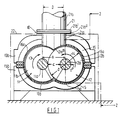
- the press is provided with two mutually parallel, horizontal press screws 11, 12 the directions of rotation of which are shown by arrows 13 and 14 in Fig. 1.
- the screws 11, 12 comprise a core 11a and 12a respectively and a screw-shaped wing 11b and 12b respectively fastened to the core.
- the screws 11, 12 are illustrated in mirror image form with opposite directions of rotation, where the screw 11 is shown with a direction of rotation (see the arrow 13) corresponding to the clockwise direction, while the screw 12 is shown with a direction of rotation (see the arrow 14) in the counterclockwise direction.
- a centre distance a (Fig. 1) between the screws and an equivalent pitch b (Fig. 2) in each of the screws and a distance c (Fig. 1) between outer surfaces of the cores 11a, 12a plus an outer screw diameter d (Fig. 1) at the periphery of wings of the screws.
- the pitch b in the illustrated embodiment is approximately 2/3 of the screw diameter.
- the distance c between outer surfaces of the cores is approximately equal to diameter d' (Fig. 1) of the core which in turn constitutes approximately 1/3 of the outer diameter d of the screw.
- the screws are surrounded below by a lower basket 15 with associated sieve sheet 15a and are surrounded above by an upper basket 16 with associated sieve sheet 16a.
- the lower basket is reinforced with a stand 15b, while the upper basket 16 is reinforced with an equivalent series of bridges 16b which are separately fixed with tension bolts and the like to the associated stand 15b.
- One end of the screws as shown at 12c in Fig. 2, is shown mounted in connection with an end cover 17.
- the screw cores 11a, 12a project endwise outside the end cover 17, where they are mounted in a bearing 18.
- a substantially vertically extending feed hopper 21 which comprises a short lower section 21a and an elongate upper main section 21b. Both sections 21a, 21b have a corresponding inner diameter D and both extend rectilinearly in alignment with each other.
- the feed hopper 21 is lined with a special friction-reducing material.
- inner diameter D of the feed hopper is shown equal to the centre distance a between the screws 11, 12, so that a uniformly thick string of the material which is supplied to the press can be fed directly to the intermediate space between the screws.
- a somewhat smaller diameter D than that which is illustrated in Fig. 1, will also be practically applicable, while on the other hand a diameter D greater than that which is shown in Fig. 1, reduces the effect of the solution according to the invention.
- the outlet opening 21c is not designed in one and the same plane, but is shown at one level at the top of she screw threads and at another, lower level at the centre plane centrally between the screws.
- Outlet opening 21c of the feed hopper 21 is localised just at the top of the press screws, centrally between the press screws, and has a breadth dimension equal to or less than the centre distance between the press screws.
- Radially outside the feed hopper the upper press basket is arranged, so that the feed hopper projects axially just within (below) the top portion of the press basket. This applies preferably at both ends of the outlet opening, regarded in the longitudinal direction of the press, but if desired the feed hopper can project downwardly between the screws only at the one end, for example only at the one end which faces inwardly into the press towards its discharge end.
- the illustrated short, lower section 21a is fastened at the rear edge via a lower fastening flange 21a' directly to the end cover 17 and at the front edge directly to an adjacent bridge member 16b.
- the section 21a is terminated at a level just above the generatrix of the press as indicated by chain lines 22 (Fig. 2).
- the upper, elongate section 21b which constitutes the main section of the feed hopper 21 and which can have a height dimension of several metres, is flangedly connected via an upper fastening flange 21b' directly to upper fastening flange 21a'' of the lower section 21a.
- the lower section 21a has an outlet which is particularly adapted to the inlet of the press, the section 21a projecting along the whole periphery a distance below its lower fastening flange 21a'.
- the feed hopper 21 is designed so that the lower portion 21a''' of the section 21a centrally in the press projects an additional distance downwardly into the cleft between screw wings 11b, 12b of the two screws 11, 12, more specifially the lower portion 21a''' projects further downwards at both opposite ends of the portion 21a''', as shown in Fig. 2.
- the said lower portion 21a''' By means of the said lower portion 21a''', one can ensure that the flow of material from the feed hopper is led in a concentrated and accurate manner directly into place in the intermediate spaces or the ducts between the press screws. Furthermore one can ensure that the said lower portion 21a''' forms a mechanical blocking arrangement or guard arrangement, which can prevent at least certain portions of the flow of material in the press from being pushed into the path of the flow of material from the feed hopper. It is assumed that the extended lower portion 21a''' of the feed hopper will effectively prevent the backward flow of material from the press back to the feed hopper.
- a bottle neck-like passage 30 and 31 respectively is shown in the screw cores 11a and 12a, reckoned from the bearing-forming end of the screw cores towards the main portion of the screw cores as indicated to the right in Fig. 2.
- Fig. 3 there is obtained hereby in the extension of the feed hopper a relatively large intake area between the screw cores.
- the pulsating movement has been changed by placing the thread crests of the screws axially close to each other as is shown in Fig. 2.
- wings 11b, 12b of the screws 11, 12 according to Fig. 2 and 3 are arranged tightly up to each other ("wing-to-wing").
- a larger common intake area between the press screws is obtained hereby and the pulsating action of the press screws can thereby be dampened to a significant degree, the press screws jointly pushing the supplied material downwardly and inwardly into the press by means of the two screw wings moveable towards each other and moveable relatively close to each other, and thereby ensuring a uniform flow of material to the lower part of the press.
Landscapes
- Engineering & Computer Science (AREA)
- Mechanical Engineering (AREA)
- Filling Or Emptying Of Bunkers, Hoppers, And Tanks (AREA)
Claims (4)
- Anordnung in einer sich im wesentlichen horizontal erstreckenden Doppelschneckenpresse (10) mit einem gemeinsamen Einfülltrichter (21), der sich nach unten zu den Preßschnecken erstreckt, eine große Höhe in bezug auf die Breiten- und/oder Längenabmessungen des Einfüllstrichers hat, wobei sich die Flügel (11b, 12b) der Preßschnecken (11, 12) in einer Richtung aufeinander zu nach unten in den Zwischenraum zwischen entsprechenden Kernen (11a, 12a) der Preßschnecken (11, 12) drehen, dadurch gekennzeichnet, daß die Querschnittsfläche des Einfülltrichters (21) über die gesamte Höhe des Einfülltrichters gleich oder im wesentlichen gleich ist, und daß die Auslaßöffnung (21c) des Einfülltrichters (21), die sich direkt oberhalb der Preßschnecken befindet, über einen relativ offenen und ungehinderten Durchgang zwischen den Preßschnecken (11, 12) direkt mit der unteren Trommel (15) der Presse in Verbindung steht, wobei die Auslaßöffnung (21c) des Einfülltrichters (21) eine Breitenabmessung (D) quer zur Presse aufweist, die im wesentlichen genauso groß ist wie oder etwas geringer als der Mittenabstand (A) zwischen den Preßschnecken (11, 12) wobei die Schneckenflügel (11b, 12b) der Preßschnecken (11, 12), die relativ dünnwandig sind, im wesentlichen Flügel an Flügel in und an dem Einlaßende der Presse angeordnet sind und so eine relativ große Querschnittsfläche zwischen Kernen (11a, 12a) der Schnecken (11, 12) und zwischen Flügelabschnitten der Schnecken bilden, die paarweise Flügel an Flügel aufeinandertreffen, und ein Abstand zwischen Außenflächen der Schneckenkerne (11a, 12a) an dem Einlaßende der Presse genauso groß ist wie oder größer als der Durchmesser des Schneckenkerns.
- Anordnung nach Anspruch 1, dadurch gekennzeichnet, daß der Einfülltrichter auf an sich bekannte Weise eine zylindrische Rohrform mit gleichmäßigem Durchmesser hat, d.h. daß die Breitenabmessung dem Innendurchmesser (D) des Einfülltrichters entspricht.
- Anordnung nach Anspruch 1 oder 2, dadurch gekennzeichnet, daß die Breitenabmessung (D) des Einfülltrichters (21) im wesentlichen der Schneckensteigung (b) am Auslaßende (21c) des Einfülltrichters entspricht.
- Anordnung nach einem der Ansprüche 1 bis 3, dadurch gekennzeichnet, daß die Kerne (11a, 12a) der beiden Preßschnecken (11, 12) am Einlaßende der Presse einen Kerndurchmesser haben, der ungefähr dem Kerndurchmesser am Lagerungsende des Kerns gleich ist, um eine größtmögliche Einlaßfläche zwischen den Schnecken zu gewährleisten, und vorzugsweise flaschenhalsartige Durchgänge (30, 31) zwischen dem Lagerungsende des Kerns und dem Kern unterhalb des Einlaßendes der Presse bilden.
Priority Applications (1)
| Application Number | Priority Date | Filing Date | Title |
|---|---|---|---|
| AT91903915T ATE113529T1 (de) | 1991-02-04 | 1991-02-04 | Einspeisevorrichtung für eine doppelschneckenpresse. |
Applications Claiming Priority (1)
| Application Number | Priority Date | Filing Date | Title |
|---|---|---|---|
| PCT/NO1991/000013 WO1992013711A1 (en) | 1991-02-04 | 1991-02-04 | Arrangement in intake for double-screw press |
Publications (2)
| Publication Number | Publication Date |
|---|---|
| EP0571376A1 EP0571376A1 (de) | 1993-12-01 |
| EP0571376B1 true EP0571376B1 (de) | 1994-11-02 |
Family
ID=19907659
Family Applications (1)
| Application Number | Title | Priority Date | Filing Date |
|---|---|---|---|
| EP91903915A Expired - Lifetime EP0571376B1 (de) | 1991-02-04 | 1991-02-04 | Einspeisevorrichtung für eine doppelschneckenpresse |
Country Status (4)
| Country | Link |
|---|---|
| EP (1) | EP0571376B1 (de) |
| JP (1) | JPH06504724A (de) |
| DE (1) | DE69105000D1 (de) |
| WO (1) | WO1992013711A1 (de) |
Family Cites Families (3)
| Publication number | Priority date | Publication date | Assignee | Title |
|---|---|---|---|---|
| SE91789C1 (de) * | ||||
| US3021782A (en) * | 1959-03-27 | 1962-02-20 | Baur Bros Co | Dewatering device and pressure feeder |
| FR2560817B1 (fr) * | 1984-03-08 | 1988-06-24 | Creusot Loire | Machine a vis de traitement de matiere |
-
1991
- 1991-02-04 EP EP91903915A patent/EP0571376B1/de not_active Expired - Lifetime
- 1991-02-04 JP JP3504023A patent/JPH06504724A/ja active Pending
- 1991-02-04 DE DE69105000T patent/DE69105000D1/de not_active Expired - Lifetime
- 1991-02-04 WO PCT/NO1991/000013 patent/WO1992013711A1/en not_active Ceased
Also Published As
| Publication number | Publication date |
|---|---|
| JPH06504724A (ja) | 1994-06-02 |
| DE69105000D1 (de) | 1994-12-08 |
| WO1992013711A1 (en) | 1992-08-20 |
| EP0571376A1 (de) | 1993-12-01 |
Similar Documents
| Publication | Publication Date | Title |
|---|---|---|
| CA2135757C (en) | Screw press | |
| CA2688323C (en) | Plug screw feeder for feeding cellulose pulp/chips | |
| EP0432388B1 (de) | Flügelzellenpumpe zum Fördern von pasteusen Massen, insbesondere von Wurstbrät | |
| US5676827A (en) | Apparatus for discharge of sediment from a tank | |
| CA2153385A1 (en) | Pumping process for operating a multi-phase screw pump and pump | |
| NO852157L (no) | Syklonseparator | |
| CA1058547A (en) | Screw conveyor having stopper bar means | |
| US3949888A (en) | Silo, especially for heavy flowing chemical and mineral substances | |
| WO2003035971A1 (en) | Container with discharging device | |
| NZ538865A (en) | Installation for hydraulically filling crates with floating objects such as fruits and having a single double-acting pump | |
| CA2022968A1 (en) | Method and apparatus for conveying bottles to a bottle processing machine | |
| US4473327A (en) | Apparatus for injecting pulverulent material | |
| WO1992013711A1 (en) | Arrangement in intake for double-screw press | |
| US6675958B2 (en) | Tube conveyor | |
| US7438550B2 (en) | Plant for the preparation of materials | |
| EP1317336A1 (de) | Vorrichtung zur abtrennung einer substanz in zwei phasen | |
| NO167903B (no) | Anordning ved innloep for to-skruepresse | |
| CA2032622A1 (en) | Silo with a discharge means | |
| EP0099000B1 (de) | Kolbenmaschine mit sternförmig angeordneten Zylindern | |
| DE69401500T2 (de) | Druckdichte schleuse | |
| EP2966014B1 (de) | Schneckenpumpe zum Fördern von Schüttgütern | |
| DE2713136A1 (de) | Vorrichtung zum lagern und foerdern von beton und anderen breiigen massen | |
| DE3715994C2 (de) | ||
| CN209758391U (zh) | 复合肥料斗出口的落料位置控制机构 | |
| EP0251258B1 (de) | Stückholz-Beschickungseinrichtung für Heizkessel |
Legal Events
| Date | Code | Title | Description |
|---|---|---|---|
| PUAI | Public reference made under article 153(3) epc to a published international application that has entered the european phase |
Free format text: ORIGINAL CODE: 0009012 |
|
| 17P | Request for examination filed |
Effective date: 19930804 |
|
| AK | Designated contracting states |
Kind code of ref document: A1 Designated state(s): AT BE CH DE DK ES FR GB GR IT LI LU NL SE |
|
| 17Q | First examination report despatched |
Effective date: 19940114 |
|
| GRAA | (expected) grant |
Free format text: ORIGINAL CODE: 0009210 |
|
| AK | Designated contracting states |
Kind code of ref document: B1 Designated state(s): AT BE CH DE DK ES FR GB GR IT LI LU NL SE |
|
| PG25 | Lapsed in a contracting state [announced via postgrant information from national office to epo] |
Ref country code: IT Free format text: LAPSE BECAUSE OF FAILURE TO SUBMIT A TRANSLATION OF THE DESCRIPTION OR TO PAY THE FEE WITHIN THE PRE;WARNING: LAPSES OF ITALIAN PATENTS WITH EFFECTIVE DATE BEFORE 2007 MAY HAVE OCCURRED AT ANY TIME BEFORE 2007. THE CORRECT EFFECTIVE DATE MAY BE DIFFERENT FROM THE ONE RECORDED.SCRIBED TIME-LIMIT Effective date: 19941102 Ref country code: NL Effective date: 19941102 Ref country code: DK Effective date: 19941102 Ref country code: ES Free format text: THE PATENT HAS BEEN ANNULLED BY A DECISION OF A NATIONAL AUTHORITY Effective date: 19941102 Ref country code: FR Effective date: 19941102 Ref country code: CH Effective date: 19941102 Ref country code: GR Free format text: LAPSE BECAUSE OF FAILURE TO SUBMIT A TRANSLATION OF THE DESCRIPTION OR TO PAY THE FEE WITHIN THE PRESCRIBED TIME-LIMIT Effective date: 19941102 Ref country code: AT Effective date: 19941102 Ref country code: BE Effective date: 19941102 Ref country code: LI Effective date: 19941102 |
|
| REF | Corresponds to: |
Ref document number: 113529 Country of ref document: AT Date of ref document: 19941115 Kind code of ref document: T |
|
| REF | Corresponds to: |
Ref document number: 69105000 Country of ref document: DE Date of ref document: 19941208 |
|
| PG25 | Lapsed in a contracting state [announced via postgrant information from national office to epo] |
Ref country code: SE Effective date: 19950202 |
|
| PG25 | Lapsed in a contracting state [announced via postgrant information from national office to epo] |
Ref country code: DE Effective date: 19950203 |
|
| PGFP | Annual fee paid to national office [announced via postgrant information from national office to epo] |
Ref country code: GB Payment date: 19950208 Year of fee payment: 5 |
|
| REG | Reference to a national code |
Ref country code: CH Ref legal event code: PL |
|
| PG25 | Lapsed in a contracting state [announced via postgrant information from national office to epo] |
Ref country code: LU Free format text: LAPSE BECAUSE OF NON-PAYMENT OF DUE FEES Effective date: 19950228 |
|
| EN | Fr: translation not filed | ||
| NLV1 | Nl: lapsed or annulled due to failure to fulfill the requirements of art. 29p and 29m of the patents act | ||
| PLBE | No opposition filed within time limit |
Free format text: ORIGINAL CODE: 0009261 |
|
| STAA | Information on the status of an ep patent application or granted ep patent |
Free format text: STATUS: NO OPPOSITION FILED WITHIN TIME LIMIT |
|
| 26N | No opposition filed | ||
| PG25 | Lapsed in a contracting state [announced via postgrant information from national office to epo] |
Ref country code: GB Effective date: 19960204 |
|
| GBPC | Gb: european patent ceased through non-payment of renewal fee |
Effective date: 19960204 |