EP0571201B1 - Electron multiplying device - Google Patents
Electron multiplying device Download PDFInfo
- Publication number
- EP0571201B1 EP0571201B1 EP93303890A EP93303890A EP0571201B1 EP 0571201 B1 EP0571201 B1 EP 0571201B1 EP 93303890 A EP93303890 A EP 93303890A EP 93303890 A EP93303890 A EP 93303890A EP 0571201 B1 EP0571201 B1 EP 0571201B1
- Authority
- EP
- European Patent Office
- Prior art keywords
- dynodes
- sequence
- electron multiplier
- housing
- base
- Prior art date
- Legal status (The legal status is an assumption and is not a legal conclusion. Google has not performed a legal analysis and makes no representation as to the accuracy of the status listed.)
- Expired - Lifetime
Links
Images


Classifications
-
- H—ELECTRICITY
- H01—ELECTRIC ELEMENTS
- H01J—ELECTRIC DISCHARGE TUBES OR DISCHARGE LAMPS
- H01J43/00—Secondary-emission tubes; Electron-multiplier tubes
- H01J43/04—Electron multipliers
-
- H—ELECTRICITY
- H01—ELECTRIC ELEMENTS
- H01J—ELECTRIC DISCHARGE TUBES OR DISCHARGE LAMPS
- H01J43/00—Secondary-emission tubes; Electron-multiplier tubes
- H01J43/04—Electron multipliers
- H01J43/28—Vessels, e.g. wall of the tube; Windows; Screens; Suppressing undesired discharges or currents
Definitions
- This invention relates to an ion (electron) multiplier for detecting or measuring energy beams of electrons, ions, charge particles, ultraviolet rays, soft X-rays, etc.
- the ion multiplying units have various types.
- Conventional quarter-cylindrical dynodes are substantially alternately arranged in a direction of incidence of energy beams.
- the arrangement of FIG. 1 is the typical one which is the so-called box-and-grid-type.
- Resistors are inserted between the respective dynodes DY and their adjacent ones.
- the resistors equidivide a voltage applied between a first-stage dynode DY1 and a final-stage dynode DY16.
- respective dynodes DY are supported, enclosed by respective support frames 1.
- Each support frame 1 is made of a conducting material and is electrically connected to the associated dynode DY.
- the ion multiplier further comprises two support rods 3 which are secured to a holder 2 of a thin steel plate and are parallel with each other. These support rods 3 are inserted in holes 4 of each support frame 1 to support the dynodes by the support rods 3. A gap between each support frame 1 and its adjacent one is retained constant by spacers 5 through which the support rods 3 are inserted.
- resistors R are disposed in one row on one of the rows of the dynodes. Leads L of each resistor R are welded respectively to vertically adjacent ones of the support frames 1.
- the above-described ion multiplying device is installed in a vacuum vessel with an energy beam source built in. But it is a problem that when the holder of a thin steel plate is not strong enough to install the device in the vessel. In addition, the dynodes are exposed, and need careful handling.
- the installation of the ion multiplying device is followed by drawing air out of the vessel, But the dynodes, which are exposed in the vessel, are subjected to air streams when the air of the vessel is evacuated. Sometimes the air streams contain dust, and the dust sticks to the surfaces of the dynodes, which may cause erroneous measurements. This problem also occurs when, after measurements, the vacuum vessel is released, and air flows into the vessel from the outside. Also in operations in vacuum, oil used in a vacuum pump, sample solvents may be attached onto the surfaces of the dynodes, and as the result, gain of the multiplying device may be degraded.
- energy beams not to be measured e.g., scattered energy beams
- energy beams are incident on the sides of the ion multiplying device to enter the exposed dynodes.
- plasmas are used, and in some cases, ultraviolet radiation from the plasmas are incident on the dynodes. These energy beams are a cause for noises.
- an electron multiplier comprising : a sequence of dynodes arranged to receive at one end an incident beam of radiation ; a base for supporting the sequence of dynodes ; and a housing mounted to the base and enclosing the sequence of dynodes.
- the invention aims to provide an ion multiplying device which has sufficient strength and is easy to handle, and can prevent the intrusion of unnecessary energy beams.
- an electron multiplier comprising: a sequence of dynodes arranged to receive at one end an incident beam of radiation; a base for supporting the sequence of dynodes; and a housing mounted to the base and enclosing the sequence of dynodes; characterised in that: the sequence of dynodes is supported at the other end thereof by the base; and the housing has a window disposed therein for permitting passage of said incident beam of radiation to said one end of the sequence of dynodes.
- the opening is of substantially the same shape as the window.
- the housing may be formed of a magnetic metal.
- the electron multiplier further comprises a pair of insulating support plates for supporting the sequence of dynodes, the support plates being secured to the base.
- the housing may have positioning slots formed therein; the support plates having tabs which are inserted in the slots when the housing is secured to the base.
- the electron multiplier further comprises an insulating filler plate disposed between said one end of the sequence of dynodes and the housing, the filler plate defining an opening aligned with the window for permitting passage of said incident beam of radiation to said one end of the sequence of dynodes.
- the electron multiplier may comprise a baffle disposed between said one end of the sequence of dynodes and the housing, the baffle defining a hole aligned with the window for permitting passage of said incident beam of radiation to said one end of the sequence of dynodes, the baffle absorbing or reflecting incident beams not directed toward said one end of the sequence of dynodes.
- the hole is larger than the window, the baffle comprising a plurality of black-colored spaced plates.
- the invention extends to a mass spectra analyser comprising a vacuum containing an electron multiplier as aforementioned.
- the ion multiplying device includes, as does the above-described conventional device, an ion multiplying unit E including a plurality of stages of dynodes DY (16 stages in this embodiment), and a collecting electrode (anode) for capturing electrons emitted from the final-stage dynode DY 16.
- the respective dynodes DY have a potential difference with respect to their downwardly adjacent ones so that they emit secondary electrons to the latter.
- the ion multiplying unit E includes a voltage dividing circuit of FIG. 8. Resistors R are inserted between the respective dynodes and their adjacent ones. A resistor R is inserted between the final-stage dynode DY 16 and the earth.
- the resistors R, the dynodes DY and the collecting electrode A are mounted between two support plates 10a, 10b of ceramics which are parallel with each other.
- Each support plate 10a, 10b is substantially rectangular.
- a block 11 is secured to one ends of the support plates 10a, 10b between both support plates by bolts and nuts 12.
- the block 11 is secured by screws to the central portion of a substantially square base 13.
- the support plates 10a, 10b are fixed to the base 13 in parallelism with each other.
- the base 13 is formed of a relatively thick stainless steel plate, and is so rigid that the base 13 is not deformed by normal uses.
- the hole 14 nearest to the corner is for mounting the ion multiplying device to, e.g., a vacuum vessel (not shown).
- the other holes 15, 15 are for mounting on the base 13 a casing which will be described later.
- the dynodes DY are arranged substantially alternately between the support plates 10a, 10b in the longitudinal direction thereof.
- the first-stage to the third-stage dynodes DY1 ⁇ DY3 which are relatively larger are arranged in the so-called box-and-grid-type arrangement, and the other smaller dynodes DY4 ⁇ DY 16 are arranged in the so-called line focus-type arrangement or linear focus arrangement.
- an energy beam enters along the longitudinal axis of the support plates 10a, 10b and impinges on the concave surface of the first-stage dynode DY1, and secondary electrons are emitted to multiply electrons.
- the secondary electrons are led to the concave surface of the second-stage dynode DY2.
- secondary electrons are led to a next stage-dynode and finally to the last-stage dynode DY16, which is nearest to the base 13.
- the collecting anode A is disposed at a position where the anode A can receive the electrons emitted from the final-stage dynode DY 16.
- a plurality of recesses are formed at a set interval in the longitudinal edges to each support plate 10a, 10b.
- the resistors of the voltage dividing circuit are mounted between the support plates 10a, 10b by the recesses 17.
- a resistor R is disposed between a pair of the recesses at the same height and is secured by inserting the leads of the resistors in recesses of the pair with the forward ends of the leads welded to the forward ends of tabs of the associated dynode DY.
- 9 resistors R are disposed on one side, and on the other side 7 resistors are disposed.
- the first-stage dynode DY1, the collecting electrode A and the final-stage dynode DY16 are connected to hermetic terminals 18 by a ceramic piped conductor 19.
- a metal plate 20 is mounted between the upper ends of the support plates 10a, 10b. In the metal plate there is formed an incidence opening 21 at a position opposed to an energy beam entrance of the first-stage dynode DY1.
- This metal plate 20 is connected to the first-stage dynode DY1 to have the same potential as the latter so that the metal plate has shielding function and also as a reinforcement of the ion multiplier assembly.
- the ion multiplier further comprises a casing 16 for protectively housing the dynodes DY, etc.
- the casing 16 has a shape of an upside-down cup, and includes a cylindrical portion 16a surrounding the support plates 10a, 10b secured to the base 13 and the hermetic terminals 18, an outward flange 16b formed in one-piece on the lower end of the cylindrical portion 16a, and a top surface 16c closing the top of the cylindrical portion 16a.
- the casing 16 is made of a magnetic metal, Permalloy or others, for the protection from the influence of the magnetic field.
- the flange 16b has a substantially rectangular shape as the base 13. Three holes 23, 22, 23 are formed in each corner of the flange 16b. When the casing 16 is mounted on the base 13 at a set position, each corner of flange 16b and that of the base 13 agree with each other with the holes 23, 22, 23 and the holes 15, 14, 15 respectively aligned with each other. A vis 24 is inserted through the inner holes 15, 23 and is fastened with a nut 25 to thereby secure the casing to the base 13.
- An entrance window 26 is formed in the top surface of the casing 16.
- the entrance window 26 is for inletting energy beams and is brought into alignment with the incidence opening 21 of the metal plate 20 and with the energy beam entrance of the first-stage dynode DY1.
- slots 27 in the top surface of the casing 16 there are formed 4 slots 27 in addition to the entrance window 26.
- the slots 27 receive tabs formed upward on the upper edges of the support plates 10a, 10b when the casing 16 is mounted on the base 13 at the set position.
- the assembly of the slots 27 and the tabs 28 facilitate the positioning of the casing 16, and the alignment of the incidence opening 21 with the entrance window 26.
- the ion multiplying device is secured by bolts to a mounting place, such as a vacuum flange or others, by means of the holes 14, 22 of the casing 13 and of the lange of the casing 16.
- the casing 13 has a rigidity sufficient to secure the ion multiplying unit E to the set position. Since the dynodes DY, etc. are housed in the casing 16, the fabricating operation can be made without paying special attention to their interference with the other members.
- FIG. 9 shows the ion multiplying device disposed in a vacuum vessel 40.
- the device of FIG. 9 is a Mass spectra analyzer. Inside the vacuum vessel 40 the ion multiplying device is disposed on the left end. A sample gas introduction chamber 41 is disposed opposed to the ion multiplying device for introducing sample gas into the vacuum vessel 40.
- an ion source 42 for ionizing the introduced sample gas and emitting ionized particles to the ion multiplying device.
- the ionized particles emitted from the ion source 42 take curved orbits when they pass through the ion analyzer 43, and only specific ones of the ionized particles selectively arrive at the ion multiplying device.
- Vacuum pumps 44, 45 are connected to the sample gas introduction chamber 41 and the vacuum chamber 40 respectively through a vacuum valves 46, 47 so that residual gas in their associated spaces are evacuated to maintain the interiors of the spaces at a vacuum atmosphere.
- the ion multiplying device is mounted in a vacuum vessel as in this case, the interior of the vessel is evacuated before a measurement, but the dynodes DY, etc., which are housed in the casing 16 are not exposed to the air flow.
- the risk of dust sticking to the dynodes DY is much reduced.
- Even when the dynodes DY are left in the air, the dynodes DY housed in the casing 16 are much less contaminated in comparison with those without the casing 16. Gain deterioration of the ion multiplying device due to backward diffusion of vacuum oil, sample solvents, etc. in an evacuating operation can be much reduced.
- the casing 16 shields off energy beams, as of neutrons, which might be irregularly reflected to adversely enter the ion multiplying device from the sides, and background ultraviolet radiation in mass analysis preventively from entering the dynodes DY.
- reference numeral 30 represents an insulator (filler plate).
- the insulator 30 is disposed between the metal plate 20 and the top surface 16c of the casing 16.
- a passage opening 32 of the same shape as the entrance window 26 and the incidence opening 21.
- a gap is formed between the top surface 16c of the casing 16 and the metal plate 20.
- the insulator 30 can have various forms. It is preferable for sealing the gap that is shown, the insulator 30 has a cylindrical shape having an outer diameter substantially equal to an inner diameter of the casing 16. In the case that the insulator 30 has such cylindrical shape, positioning slots 31 are formed in the insulator 30 so as to be into alignment with the slots 27 . The tabs 28 of the support plates 10a, 10b are inserted into the slots 31 and the slots 27, whereby the passage opening 32 of the insulator 30 for inletting energy beams is brought into alignment with the entrance window 26 of the casing 16, the incidence opening 21 of the meal plate 20 and the energy beam receiving surface of the first-stage dynode DY 1.
- FIG. 7 is a sectional view of another example of the casing 16. This example is different from the casing involved in the above-described embodiment in that in the former the upper end of a cylindrical portion 16a of the casing 16 is extended upward beyond a top surface 16c.
- a baffle (energy beam introducing members) 35 in the form of a plurality of rings is mounted on the inside peripheral surface of the extended portion 16d of the cylindrical portion 16a.
- the baffle 35 comprises a plurality of metal plates 36 each having both sides colored in black. Each metal plate 36 has an opening formed in central part thereof. The opening 36a is larger than the entrance window 26 below the metal plate 36. The openings of the respective metal plates define an energy beam introducing hole.
- the baffle 35 is for absorbing or reflecting energy beams entering from the sides, which are not to be measured so as to prohibit their entrance through the entrance window 26 of the casing 16. Because of the baffle 35, background ultraviolet radiation and neutral moleculed, etc. which are problems with mass analysis can be usefully reduced.
- the baffle 35 can have various shapes for preventing the intrusion of the background molecules and ultraviolet radiation.
- the dynodes DY housed in the casing 16 are mounted on the two support plates 10a, 10b, but this invention is also applicable to the structure of, e.g., FIG. 2.
- the ion multiplying device includes the casing.
- the casing can protect the ion multiplying unit E including the dynodes and the resistors, etc. from unnecessary energy beams not to be measured and dust, the backward diffusion of vacuum oil and sample solvents, etc. Unnecessary energy beams cause noises, and to shield off the unnecessary energy beams improves achievement of the ion multiplying device. Dust, vacuum oil, etc. are hindered from sticking to the dynodes, whereby the deterioration of gains of the ion multiplying device can be precluded.
- the casing protects the dynodes, etc. from external forces, such as impacts, etc.
- the base has a sufficient rigidity which facilitates the handling the ion multiplying device.
Landscapes
- Measurement Of Radiation (AREA)
Description
- This invention relates to an ion (electron) multiplier for detecting or measuring energy beams of electrons, ions, charge particles, ultraviolet rays, soft X-rays, etc.
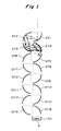
- As schematically shown in FIG. 1, in an ion multiplying device, energy beams, as of electrons or others, impinge on dynodes of the ion multiplying unit to multiply and emit secondary electrons, and the collecting electrodes (anodes) A collect the emitted secondary electrons for detection.
- The ion multiplying units have various types. Conventional quarter-cylindrical dynodes are substantially alternately arranged in a direction of incidence of energy beams. The arrangement of FIG. 1 is the typical one which is the so-called box-and-grid-type.
- Resistors are inserted between the respective dynodes DY and their adjacent ones. The resistors equidivide a voltage applied between a first-stage dynode DY1 and a final-stage dynode DY16.
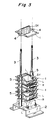
- This is the basic structure of the ion multiplying units. The general actual assembly of the ion multipliers is shown in FIGs. 2 and 3.
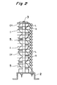
- In the ion multiplier of FIGs. 2 and 3, respective dynodes DY are supported, enclosed by respective support frames 1. Each support frame 1 is made of a conducting material and is electrically connected to the associated dynode DY. The ion multiplier further comprises two
support rods 3 which are secured to aholder 2 of a thin steel plate and are parallel with each other. Thesesupport rods 3 are inserted inholes 4 of each support frame 1 to support the dynodes by thesupport rods 3. A gap between each support frame 1 and its adjacent one is retained constant byspacers 5 through which thesupport rods 3 are inserted. - In this conventional ion multiplying device, resistors R are disposed in one row on one of the rows of the dynodes. Leads L of each resistor R are welded respectively to vertically adjacent ones of the support frames 1.
- For the measurement of energy beams, as of ions, the above-described ion multiplying device is installed in a vacuum vessel with an energy beam source built in. But it is a problem that when the holder of a thin steel plate is not strong enough to install the device in the vessel. In addition, the dynodes are exposed, and need careful handling.
- The installation of the ion multiplying device is followed by drawing air out of the vessel, But the dynodes, which are exposed in the vessel, are subjected to air streams when the air of the vessel is evacuated. Sometimes the air streams contain dust, and the dust sticks to the surfaces of the dynodes, which may cause erroneous measurements. This problem also occurs when, after measurements, the vacuum vessel is released, and air flows into the vessel from the outside. Also in operations in vacuum, oil used in a vacuum pump, sample solvents may be attached onto the surfaces of the dynodes, and as the result, gain of the multiplying device may be degraded.
- Furthermore, in some cases energy beams not to be measured, e.g., scattered energy beams, are incident on the sides of the ion multiplying device to enter the exposed dynodes. For analysis of ions of some kinds, plasmas are used, and in some cases, ultraviolet radiation from the plasmas are incident on the dynodes. These energy beams are a cause for noises.
- From US-A-3 272 984 an electron multiplier is known, comprising : a sequence of dynodes arranged to receive at one end an incident beam of radiation ; a base for supporting the sequence of dynodes ; and a housing mounted to the base and enclosing the sequence of dynodes.
- In view of these problems, this invention has been made. The invention aims to provide an ion multiplying device which has sufficient strength and is easy to handle, and can prevent the intrusion of unnecessary energy beams.
- According to the invention there is provided an electron multiplier comprising: a sequence of dynodes arranged to receive at one end an incident beam of radiation; a base for supporting the sequence of dynodes; and a housing mounted to the base and enclosing the sequence of dynodes; characterised in that: the sequence of dynodes is supported at the other end thereof by the base; and the housing has a window disposed therein for permitting passage of said incident beam of radiation to said one end of the sequence of dynodes.
- It is preferable that the opening is of substantially the same shape as the window.
- The housing may be formed of a magnetic metal.
- Preferably the electron multiplier further comprises a pair of insulating support plates for supporting the sequence of dynodes, the support plates being secured to the base.
- The housing may have positioning slots formed therein;
the support plates having tabs which are inserted in the slots when the housing is secured to the base. - It is preferable that the electron multiplier further comprises an insulating filler plate disposed between said one end of the sequence of dynodes and the housing, the filler plate defining an opening aligned with the window for permitting passage of said incident beam of radiation to said one end of the sequence of dynodes.
- The electron multiplier may comprise a baffle disposed between said one end of the sequence of dynodes and the housing, the baffle defining a hole aligned with the window for permitting passage of said incident beam of radiation to said one end of the sequence of dynodes, the baffle absorbing or reflecting incident beams not directed toward said one end of the sequence of dynodes.
- It is preferable that the hole is larger than the window, the baffle comprising a plurality of black-colored spaced plates.
- The invention extends to a mass spectra analyser comprising a vacuum containing an electron multiplier as aforementioned.
- The present invention will become more fully understood from the detailed description of embodiments given hereinbelow and the accompanying drawings which are given by way of illustration only, and thus are not to be considered as limiting the present invention.
- Further scope of applicability of the present invention will become apparent from the detailed description given hereinafter. However, it should be understood that the detailed description and specific examples, while indicating preferred embodiments of the invention, are given by way of illustration only, since various changes and modifications within the scope of the invention will become apparent to those skilled in the art from this detailed description.
-
- FIG. 1 is a schematic view explaining the principle of the ion multiplying device;
- FIG. 2 is a side view of the conventional general ion multiplying device;
- FIG. 3 is a perspective view of the ion multiplying device of FIG. 2 being assembled;
- FIG. 4 is a broken-down perspective view of the ion multiplying device according to one embodiment of this invention;
- FIG. 5 is a perspective view of the finished ion multiplying device of FIG. 4;
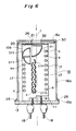
- FIG. 6 is a longitudinal sectional view of the ion multiplying device of FIG. 4;
- FIG. 7 is a sectional view of a modification of the casing used for the ion multiplying device of FIG. 4;
- FIG. 8 is a circuit diagram of a voltage dividing circuit used in the ion multiplying device of FIG. 4; and
- FIG. 9 is a block diagram of a vacuum vessel with the ion multiplying device installed in.
- Preferred embodiments of the invention will be explained with reference to the drawings attached hereto.
- In the drawings the common members are represented by common reference numerals. In the following description, "vertically, or up to down", and "horizontally, or left to right" means "vertically, or up to down" and "horizontal, or left to right" as viewed in the drawings.
- As shown in FIGs. 4 to 6, the ion multiplying device according to one embodiment of this invention includes, as does the above-described conventional device, an ion multiplying unit E including a plurality of stages of dynodes DY (16 stages in this embodiment), and a collecting electrode (anode) for capturing electrons emitted from the final-
stage dynode DY 16. The respective dynodes DY have a potential difference with respect to their downwardly adjacent ones so that they emit secondary electrons to the latter. To this end, the ion multiplying unit E includes a voltage dividing circuit of FIG. 8. Resistors R are inserted between the respective dynodes and their adjacent ones. A resistor R is inserted between the final-stage dynode DY 16 and the earth. - In this embodiment, the resistors R, the dynodes DY and the collecting electrode A are mounted between two
support plates 10a, 10b of ceramics which are parallel with each other. Eachsupport plate 10a, 10b is substantially rectangular. Ablock 11 is secured to one ends of thesupport plates 10a, 10b between both support plates by bolts andnuts 12. Theblock 11 is secured by screws to the central portion of a substantiallysquare base 13. Thus thesupport plates 10a, 10b are fixed to the base 13 in parallelism with each other. - The
base 13 is formed of a relatively thick stainless steel plate, and is so rigid that thebase 13 is not deformed by normal uses. In each corner of the base 13 there are formed threeholes hole 14 nearest to the corner is for mounting the ion multiplying device to, e.g., a vacuum vessel (not shown). Theother holes - As shown in FIG. 6, the dynodes DY are arranged substantially alternately between the
support plates 10a, 10b in the longitudinal direction thereof. The first-stage to the third-stage dynodes DY1 ∼ DY3 which are relatively larger are arranged in the so-called box-and-grid-type arrangement, and the other smaller dynodes DY4 ∼DY 16 are arranged in the so-called line focus-type arrangement or linear focus arrangement. In this arrangement, an energy beam enters along the longitudinal axis of thesupport plates 10a, 10b and impinges on the concave surface of the first-stage dynode DY1, and secondary electrons are emitted to multiply electrons. The secondary electrons are led to the concave surface of the second-stage dynode DY2. Thus secondary electrons are led to a next stage-dynode and finally to the last-stage dynode DY16, which is nearest to thebase 13. - The collecting anode A is disposed at a position where the anode A can receive the electrons emitted from the final-
stage dynode DY 16. - A plurality of recesses are formed at a set interval in the longitudinal edges to each
support plate 10a, 10b. The resistors of the voltage dividing circuit are mounted between thesupport plates 10a, 10b by therecesses 17. A resistor R is disposed between a pair of the recesses at the same height and is secured by inserting the leads of the resistors in recesses of the pair with the forward ends of the leads welded to the forward ends of tabs of the associated dynode DY. In this embodiment, 9 resistors R are disposed on one side, and on theother side 7 resistors are disposed. - The first-stage dynode DY1, the collecting electrode A and the final-stage dynode DY16 are connected to
hermetic terminals 18 by a ceramic pipedconductor 19. - A
metal plate 20 is mounted between the upper ends of thesupport plates 10a, 10b. In the metal plate there is formed anincidence opening 21 at a position opposed to an energy beam entrance of the first-stage dynode DY1. Thismetal plate 20 is connected to the first-stage dynode DY1 to have the same potential as the latter so that the metal plate has shielding function and also as a reinforcement of the ion multiplier assembly. - The ion multiplier according to this embodiment further comprises a
casing 16 for protectively housing the dynodes DY, etc. Thecasing 16 has a shape of an upside-down cup, and includes acylindrical portion 16a surrounding thesupport plates 10a, 10b secured to thebase 13 and thehermetic terminals 18, anoutward flange 16b formed in one-piece on the lower end of thecylindrical portion 16a, and atop surface 16c closing the top of thecylindrical portion 16a. It is preferable that thecasing 16 is made of a magnetic metal, Permalloy or others, for the protection from the influence of the magnetic field. - The
flange 16b has a substantially rectangular shape as thebase 13. Threeholes flange 16b. When thecasing 16 is mounted on the base 13 at a set position, each corner offlange 16b and that of the base 13 agree with each other with theholes holes inner holes nut 25 to thereby secure the casing to thebase 13. - An
entrance window 26 is formed in the top surface of thecasing 16. Theentrance window 26 is for inletting energy beams and is brought into alignment with theincidence opening 21 of themetal plate 20 and with the energy beam entrance of the first-stage dynode DY1. - In this embodiment, in the top surface of the
casing 16 there are formed 4slots 27 in addition to theentrance window 26. Theslots 27 receive tabs formed upward on the upper edges of thesupport plates 10a, 10b when thecasing 16 is mounted on the base 13 at the set position. The assembly of theslots 27 and thetabs 28 facilitate the positioning of thecasing 16, and the alignment of theincidence opening 21 with theentrance window 26. - The ion multiplying device according to this embodiment is secured by bolts to a mounting place, such as a vacuum flange or others, by means of the
holes casing 13 and of the lange of thecasing 16. Thecasing 13 has a rigidity sufficient to secure the ion multiplying unit E to the set position. Since the dynodes DY, etc. are housed in thecasing 16, the fabricating operation can be made without paying special attention to their interference with the other members. - FIG. 9 shows the ion multiplying device disposed in a
vacuum vessel 40. The device of FIG. 9 is a Mass spectra analyzer. Inside thevacuum vessel 40 the ion multiplying device is disposed on the left end. A samplegas introduction chamber 41 is disposed opposed to the ion multiplying device for introducing sample gas into thevacuum vessel 40. In thevacuum vessel 40 there is provided anion source 42 for ionizing the introduced sample gas and emitting ionized particles to the ion multiplying device. The ionized particles emitted from theion source 42 take curved orbits when they pass through theion analyzer 43, and only specific ones of the ionized particles selectively arrive at the ion multiplying device. Vacuum pumps 44, 45 are connected to the samplegas introduction chamber 41 and thevacuum chamber 40 respectively through avacuum valves - In the case that the ion multiplying device is mounted in a vacuum vessel as in this case, the interior of the vessel is evacuated before a measurement, but the dynodes DY, etc., which are housed in the
casing 16 are not exposed to the air flow. The risk of dust sticking to the dynodes DY is much reduced. Even when the dynodes DY are left in the air, the dynodes DY housed in thecasing 16 are much less contaminated in comparison with those without thecasing 16. Gain deterioration of the ion multiplying device due to backward diffusion of vacuum oil, sample solvents, etc. in an evacuating operation can be much reduced. - The
casing 16 shields off energy beams, as of neutrons, which might be irregularly reflected to adversely enter the ion multiplying device from the sides, and background ultraviolet radiation in mass analysis preventively from entering the dynodes DY. - The
casing 16 made of a magnetic metal, such as Permalloy, functions as an electromagnetic shield and prevents the influence due to magnetic fields and electric fields of incident energy beams. - In FIGs. 4 and 6,
reference numeral 30 represents an insulator (filler plate). Theinsulator 30 is disposed between themetal plate 20 and thetop surface 16c of thecasing 16. In the central part of theinsulator 30 there is formed apassage opening 32 of the same shape as theentrance window 26 and theincidence opening 21. A gap is formed between thetop surface 16c of thecasing 16 and themetal plate 20. There is a very low possibility that dust and unnecessary energy beams which have entered through theentrance window 26 intrude into thecasing 16 through the gap. But theinsulator 30 can perfectly prohibit the intrusion of the dust, etc. - The
insulator 30 can have various forms. It is preferable for sealing the gap that is shown, theinsulator 30 has a cylindrical shape having an outer diameter substantially equal to an inner diameter of thecasing 16. In the case that theinsulator 30 has such cylindrical shape,positioning slots 31 are formed in theinsulator 30 so as to be into alignment with theslots 27 . Thetabs 28 of thesupport plates 10a, 10b are inserted into theslots 31 and theslots 27, whereby the passage opening 32 of theinsulator 30 for inletting energy beams is brought into alignment with theentrance window 26 of thecasing 16, theincidence opening 21 of themeal plate 20 and the energy beam receiving surface of the first-stage dynode DY 1. - FIG. 7 is a sectional view of another example of the
casing 16. This example is different from the casing involved in the above-described embodiment in that in the former the upper end of acylindrical portion 16a of thecasing 16 is extended upward beyond atop surface 16c. A baffle (energy beam introducing members) 35 in the form of a plurality of rings is mounted on the inside peripheral surface of theextended portion 16d of thecylindrical portion 16a. - The
baffle 35 comprises a plurality ofmetal plates 36 each having both sides colored in black. Eachmetal plate 36 has an opening formed in central part thereof. Theopening 36a is larger than theentrance window 26 below themetal plate 36. The openings of the respective metal plates define an energy beam introducing hole. Thebaffle 35 is for absorbing or reflecting energy beams entering from the sides, which are not to be measured so as to prohibit their entrance through theentrance window 26 of thecasing 16. Because of thebaffle 35, background ultraviolet radiation and neutral moleculed, etc. which are problems with mass analysis can be usefully reduced. Thebaffle 35 can have various shapes for preventing the intrusion of the background molecules and ultraviolet radiation. - In the above-described embodiment, the dynodes DY housed in the
casing 16 are mounted on the twosupport plates 10a, 10b, but this invention is also applicable to the structure of, e.g., FIG. 2. - As described above, the ion multiplying device according to this invention includes the casing. The casing can protect the ion multiplying unit E including the dynodes and the resistors, etc. from unnecessary energy beams not to be measured and dust, the backward diffusion of vacuum oil and sample solvents, etc. Unnecessary energy beams cause noises, and to shield off the unnecessary energy beams improves achievement of the ion multiplying device. Dust, vacuum oil, etc. are hindered from sticking to the dynodes, whereby the deterioration of gains of the ion multiplying device can be precluded.
- The casing protects the dynodes, etc. from external forces, such as impacts, etc. The base has a sufficient rigidity which facilitates the handling the ion multiplying device.
- From the invention thus described, it will be obvious that the invention may be varied in many ways. Such variations are not to be regarded as a departure from the scope of the invention, and all such modifications as would be obvious to one skilled in the art are intended to be included within the scope of the invention as defined in the following claims.
Claims (11)
- An electron multiplier comprising:a sequence of dynodes (DY1 to DY16) arranged to receive at one end an incident beam of radiation;a base (13) for supporting the sequence of dynodes; anda housing (16) mounted to the base and enclosing the sequence of dynodes;characterised in that:the sequence of dynodes (DY1 to DY16) is supported at the other end thereof by the base; andthe housing has a window (26) disposed therein for permitting passage of said incident beam of radiation to said one end of the sequence of dynodes.
- An electron multiplier as claimed in claim 1, further comprising a metal plate (20) at said one end of the sequence of dynodes (DY1 to DY16), the metal plate defining an opening (21) through which radiation can pass to the sequence of dynodes.
- An electron multiplier as claimed in claim 2, wherein the opening (21) is of substantially the same shape as the window (26).
- An electron multiplier as claimed in any preceding claim, wherein the housing (16) is formed from a magnetic metal.
- An electron multiplier as claimed in any preceding claim, further comprising a pair of insulating support plates (10a, 10b) for supporting the sequence of dynodes, the support plates being secured to said base (13).
- An electron multiplier as claimed in claim 5, wherein the housing (16) has positioning slots (27) formed therein; and
the support plates (10a, 10b) have tabs (28) which are inserted in the slots (27) when the housing is secured to the base (13). - An electron multiplier as claimed in any preceding claim, further comprising an insulating filler plate (30) disposed between said one end of the sequence of dynodes and the housing, the filler plate defining an opening (32) aligned with the window (26) for permitting passage of said incident beam of radiation to said one end of the sequence of dynodes.
- An electron multiplier as claimed in any of claims 1 to 6, further comprising a baffle (35) disposed between said one end of the sequence of dynodes and the housing, the baffle defining a hole (36a) aligned with the window (26) for permitting passage of said incident beam of radiation to said one end of the sequence of dynodes, the baffle absorbing or reflecting incident beams not directed toward said one end of the sequence of dynodes.
- An electron multiplier as claimed in claim 8, wherein the hole (36a) is larger than the window (26), the baffle (35) comprising a plurality of spaced plates (36).
- An electron multiplier as claimed in claim 9, wherein the plates (36) are coloured black.
- A mass spectra analyser comprising a vacuum vessel (40) containing an electron multiplier as claimed in any preceding claim.
Applications Claiming Priority (2)
| Application Number | Priority Date | Filing Date | Title |
|---|---|---|---|
| JP127702/92 | 1992-05-20 | ||
| JP4127702A JP2662341B2 (en) | 1992-05-20 | 1992-05-20 | Electron multiplier |
Publications (2)
| Publication Number | Publication Date |
|---|---|
| EP0571201A1 EP0571201A1 (en) | 1993-11-24 |
| EP0571201B1 true EP0571201B1 (en) | 1996-08-28 |
Family
ID=14966596
Family Applications (1)
| Application Number | Title | Priority Date | Filing Date |
|---|---|---|---|
| EP93303890A Expired - Lifetime EP0571201B1 (en) | 1992-05-20 | 1993-05-19 | Electron multiplying device |
Country Status (4)
| Country | Link |
|---|---|
| US (1) | US5446275A (en) |
| EP (1) | EP0571201B1 (en) |
| JP (1) | JP2662341B2 (en) |
| DE (1) | DE69304250T2 (en) |
Families Citing this family (13)
| Publication number | Priority date | Publication date | Assignee | Title |
|---|---|---|---|---|
| JPH07245078A (en) * | 1994-03-07 | 1995-09-19 | Hamamatsu Photonics Kk | Photomultiplier |
| JP3455588B2 (en) * | 1994-06-29 | 2003-10-14 | 浜松ホトニクス株式会社 | Photoelectric detector with cooling device and method of manufacturing the same |
| JP3054032B2 (en) * | 1994-06-29 | 2000-06-19 | 浜松ホトニクス株式会社 | Electron tube |
| JP3618013B2 (en) * | 1995-07-20 | 2005-02-09 | 浜松ホトニクス株式会社 | Photomultiplier tube |
| JPH1083788A (en) * | 1996-09-06 | 1998-03-31 | Hamamatsu Photonics Kk | Magnetic shield case |
| US5866901A (en) * | 1996-12-05 | 1999-02-02 | Mks Instruments, Inc. | Apparatus for and method of ion detection using electron multiplier over a range of high pressures |
| US5914561A (en) * | 1997-08-21 | 1999-06-22 | Burle Technologies, Inc. | Shortened profile photomultiplier tube with focusing electrode |
| JP2001351565A (en) * | 2000-06-08 | 2001-12-21 | Hamamatsu Photonics Kk | Mass spectrometer |
| JP4250353B2 (en) * | 2001-06-22 | 2009-04-08 | エドワーズ株式会社 | Vacuum pump |
| JP2006144783A (en) * | 2004-11-24 | 2006-06-08 | Pfeiffer Vacuum Gmbh | Damage preventing device connectable to flange of vacuum pump having high-speed rotor |
| WO2010125669A1 (en) * | 2009-04-30 | 2010-11-04 | キヤノンアネルバ株式会社 | Ion detection device for mass analysis, ion detection method, and production method for ion detection device |
| SG11202008683RA (en) * | 2018-03-23 | 2020-10-29 | Adaptas Solutions Pty Ltd | Particle detector having improved performance and service life |
| AU2019264856A1 (en) * | 2018-05-07 | 2020-12-10 | Adaptas Solutions Pty Ltd | Detector having improved construction |
Family Cites Families (12)
| Publication number | Priority date | Publication date | Assignee | Title |
|---|---|---|---|---|
| US2952499A (en) * | 1957-11-18 | 1960-09-13 | Philco Corp | Processing system |
| US3229143A (en) | 1961-10-06 | 1966-01-11 | Nuclide Corp | Electron multiplier device |
| US3254209A (en) * | 1962-11-29 | 1966-05-31 | Gen Dynamics Corp | Method and apparatus for increasing the ionization of impurity ions in a mass spectrometer |
| US3272984A (en) * | 1963-06-07 | 1966-09-13 | Gca Corp | Electron multiplier for measuring the flow of positively charged particles |
| US3272986A (en) * | 1963-09-27 | 1966-09-13 | Honeywell Inc | Solar heat absorbers comprising alternate layers of metal and dielectric material |
| JPS447267Y1 (en) * | 1966-04-27 | 1969-03-18 | ||
| US4431943A (en) * | 1980-12-16 | 1984-02-14 | Rca Corporation | Electron discharge device having a high speed cage |
| AU561469B2 (en) * | 1981-08-25 | 1987-05-07 | Commonwealth Scientific And Industrial Research Organisation | Electron multiplier |
| JPS6264042A (en) * | 1985-09-13 | 1987-03-20 | Shimadzu Corp | Detector for charged particle or the like |
| JPH046741A (en) * | 1990-04-25 | 1992-01-10 | Hitachi Ltd | Ion detector for mass spectrometer |
| JPH04160728A (en) * | 1990-10-23 | 1992-06-04 | Murata Mfg Co Ltd | Manufacture of secondary-electron multiplier |
| JPH04233151A (en) * | 1990-12-28 | 1992-08-21 | Murata Mfg Co Ltd | Ion detector |
-
1992
- 1992-05-20 JP JP4127702A patent/JP2662341B2/en not_active Expired - Fee Related
-
1993
- 1993-05-19 EP EP93303890A patent/EP0571201B1/en not_active Expired - Lifetime
- 1993-05-19 DE DE69304250T patent/DE69304250T2/en not_active Expired - Fee Related
- 1993-05-19 US US08/063,418 patent/US5446275A/en not_active Expired - Fee Related
Also Published As
| Publication number | Publication date |
|---|---|
| DE69304250T2 (en) | 1997-01-30 |
| JP2662341B2 (en) | 1997-10-08 |
| EP0571201A1 (en) | 1993-11-24 |
| US5446275A (en) | 1995-08-29 |
| JPH05325879A (en) | 1993-12-10 |
| DE69304250D1 (en) | 1996-10-02 |
Similar Documents
| Publication | Publication Date | Title |
|---|---|---|
| EP0571201B1 (en) | Electron multiplying device | |
| US9934952B2 (en) | Charged-particle detector and method of controlling the same | |
| EP0281413B1 (en) | Mass spectrometer for positive and negative ions | |
| US5223711A (en) | Plasma sources mass spectrometry | |
| JP2968338B2 (en) | Cycloid mass spectrometer | |
| US20240063004A1 (en) | Particle detector having improved performance and service life | |
| US5903002A (en) | Charged-particle detectors and mass spectrometers employing the same | |
| US3939344A (en) | Prefilter-ionizer apparatus for use with quadrupole type secondary-ion mass spectrometers | |
| WO2006080104A2 (en) | Electron multiplier unit and photomultiplier including the same | |
| US5561292A (en) | Mass spectrometer and electron impact ion source thereof | |
| GB2323468A (en) | Mass spectrometer total pressure collector | |
| CN114207478A (en) | Detector comprising a transmissive secondary electron emission device | |
| US20050109947A1 (en) | Ion detector | |
| US11410839B2 (en) | Electron multipliers internal regions | |
| US11139153B2 (en) | MCP assembly and charged particle detector | |
| JP2001351565A (en) | Mass spectrometer | |
| US5880458A (en) | Photomultiplier tube with focusing electrode plate having frame | |
| JP7252179B2 (en) | Ion detectors, measurement devices and mass spectrometers | |
| JP4498545B2 (en) | Ion detector and electron multiplier | |
| US3117224A (en) | High vacuum mass analyser apparatus | |
| US6818887B2 (en) | Reflector for a time-of-flight mass spectrometer | |
| GB2576813A (en) | Ion guide | |
| JPH01289063A (en) | Multichannel neutral particle analyzer | |
| JPH05217547A (en) | Mass spectrometer | |
| Doehler et al. | Crossed-field beam tester |
Legal Events
| Date | Code | Title | Description |
|---|---|---|---|
| PUAI | Public reference made under article 153(3) epc to a published international application that has entered the european phase |
Free format text: ORIGINAL CODE: 0009012 |
|
| 17P | Request for examination filed |
Effective date: 19930930 |
|
| AK | Designated contracting states |
Kind code of ref document: A1 Designated state(s): DE FR GB IT |
|
| 17Q | First examination report despatched |
Effective date: 19950317 |
|
| GRAH | Despatch of communication of intention to grant a patent |
Free format text: ORIGINAL CODE: EPIDOS IGRA |
|
| GRAH | Despatch of communication of intention to grant a patent |
Free format text: ORIGINAL CODE: EPIDOS IGRA |
|
| GRAH | Despatch of communication of intention to grant a patent |
Free format text: ORIGINAL CODE: EPIDOS IGRA |
|
| GRAA | (expected) grant |
Free format text: ORIGINAL CODE: 0009210 |
|
| AK | Designated contracting states |
Kind code of ref document: B1 Designated state(s): DE FR GB IT |
|
| ET | Fr: translation filed | ||
| ITF | It: translation for a ep patent filed |
Owner name: ING. A. GIAMBROCONO & C. S.R.L. |
|
| REF | Corresponds to: |
Ref document number: 69304250 Country of ref document: DE Date of ref document: 19961002 |
|
| PLBE | No opposition filed within time limit |
Free format text: ORIGINAL CODE: 0009261 |
|
| STAA | Information on the status of an ep patent application or granted ep patent |
Free format text: STATUS: NO OPPOSITION FILED WITHIN TIME LIMIT |
|
| 26N | No opposition filed | ||
| REG | Reference to a national code |
Ref country code: GB Ref legal event code: IF02 |
|
| PGFP | Annual fee paid to national office [announced via postgrant information from national office to epo] |
Ref country code: DE Payment date: 20050512 Year of fee payment: 13 |
|
| PG25 | Lapsed in a contracting state [announced via postgrant information from national office to epo] |
Ref country code: IT Free format text: LAPSE BECAUSE OF NON-PAYMENT OF DUE FEES;WARNING: LAPSES OF ITALIAN PATENTS WITH EFFECTIVE DATE BEFORE 2007 MAY HAVE OCCURRED AT ANY TIME BEFORE 2007. THE CORRECT EFFECTIVE DATE MAY BE DIFFERENT FROM THE ONE RECORDED. Effective date: 20050519 |
|
| PG25 | Lapsed in a contracting state [announced via postgrant information from national office to epo] |
Ref country code: DE Free format text: LAPSE BECAUSE OF NON-PAYMENT OF DUE FEES Effective date: 20061201 |
|
| PGFP | Annual fee paid to national office [announced via postgrant information from national office to epo] |
Ref country code: GB Payment date: 20070516 Year of fee payment: 15 |
|
| PGFP | Annual fee paid to national office [announced via postgrant information from national office to epo] |
Ref country code: FR Payment date: 20070510 Year of fee payment: 15 |
|
| GBPC | Gb: european patent ceased through non-payment of renewal fee |
Effective date: 20080519 |
|
| REG | Reference to a national code |
Ref country code: FR Ref legal event code: ST Effective date: 20090119 |
|
| PG25 | Lapsed in a contracting state [announced via postgrant information from national office to epo] |
Ref country code: FR Free format text: LAPSE BECAUSE OF NON-PAYMENT OF DUE FEES Effective date: 20080602 |
|
| PG25 | Lapsed in a contracting state [announced via postgrant information from national office to epo] |
Ref country code: GB Free format text: LAPSE BECAUSE OF NON-PAYMENT OF DUE FEES Effective date: 20080519 |