EP0570302B1 - A device for dispensing wire, cable or the like - Google Patents
A device for dispensing wire, cable or the like Download PDFInfo
- Publication number
- EP0570302B1 EP0570302B1 EP93401251A EP93401251A EP0570302B1 EP 0570302 B1 EP0570302 B1 EP 0570302B1 EP 93401251 A EP93401251 A EP 93401251A EP 93401251 A EP93401251 A EP 93401251A EP 0570302 B1 EP0570302 B1 EP 0570302B1
- Authority
- EP
- European Patent Office
- Prior art keywords
- box
- reel
- hub
- wire
- inter
- Prior art date
- Legal status (The legal status is an assumption and is not a legal conclusion. Google has not performed a legal analysis and makes no representation as to the accuracy of the status listed.)
- Expired - Lifetime
Links
- 230000000007 visual effect Effects 0.000 claims 1
- 230000000903 blocking effect Effects 0.000 abstract 1
- 238000010276 construction Methods 0.000 description 2
- 230000006835 compression Effects 0.000 description 1
- 238000007906 compression Methods 0.000 description 1
- 239000000463 material Substances 0.000 description 1
- 238000000034 method Methods 0.000 description 1
- 238000004804 winding Methods 0.000 description 1
Images




Classifications
-
- B—PERFORMING OPERATIONS; TRANSPORTING
- B65—CONVEYING; PACKING; STORING; HANDLING THIN OR FILAMENTARY MATERIAL
- B65H—HANDLING THIN OR FILAMENTARY MATERIAL, e.g. SHEETS, WEBS, CABLES
- B65H49/00—Unwinding or paying-out filamentary material; Supporting, storing or transporting packages from which filamentary material is to be withdrawn or paid-out
- B65H49/18—Methods or apparatus in which packages rotate
- B65H49/20—Package-supporting devices
- B65H49/32—Stands or frameworks
- B65H49/322—Enclosing boxes with supporting means for the package or reel during unwinding
-
- B—PERFORMING OPERATIONS; TRANSPORTING
- B65—CONVEYING; PACKING; STORING; HANDLING THIN OR FILAMENTARY MATERIAL
- B65H—HANDLING THIN OR FILAMENTARY MATERIAL, e.g. SHEETS, WEBS, CABLES
- B65H75/00—Storing webs, tapes, or filamentary material, e.g. on reels
- B65H75/02—Cores, formers, supports, or holders for coiled, wound, or folded material, e.g. reels, spindles, bobbins, cop tubes, cans, mandrels or chucks
- B65H75/18—Constructional details
- B65H75/22—Constructional details collapsible; with removable parts
- B65H75/2245—Constructional details collapsible; with removable parts connecting flange to hub
-
- B—PERFORMING OPERATIONS; TRANSPORTING
- B65—CONVEYING; PACKING; STORING; HANDLING THIN OR FILAMENTARY MATERIAL
- B65H—HANDLING THIN OR FILAMENTARY MATERIAL, e.g. SHEETS, WEBS, CABLES
- B65H75/00—Storing webs, tapes, or filamentary material, e.g. on reels
- B65H75/02—Cores, formers, supports, or holders for coiled, wound, or folded material, e.g. reels, spindles, bobbins, cop tubes, cans, mandrels or chucks
- B65H75/18—Constructional details
- B65H75/22—Constructional details collapsible; with removable parts
- B65H75/2254—Constructional details collapsible; with removable parts with particular joining means for releasably connecting parts
- B65H75/2272—Constructional details collapsible; with removable parts with particular joining means for releasably connecting parts releasably connected by relative rotatable movement of parts, e.g. threaded or bayonet fit
-
- B—PERFORMING OPERATIONS; TRANSPORTING
- B65—CONVEYING; PACKING; STORING; HANDLING THIN OR FILAMENTARY MATERIAL
- B65H—HANDLING THIN OR FILAMENTARY MATERIAL, e.g. SHEETS, WEBS, CABLES
- B65H75/00—Storing webs, tapes, or filamentary material, e.g. on reels
- B65H75/02—Cores, formers, supports, or holders for coiled, wound, or folded material, e.g. reels, spindles, bobbins, cop tubes, cans, mandrels or chucks
- B65H75/18—Constructional details
- B65H75/30—Arrangements to facilitate driving or braking
-
- B—PERFORMING OPERATIONS; TRANSPORTING
- B65—CONVEYING; PACKING; STORING; HANDLING THIN OR FILAMENTARY MATERIAL
- B65H—HANDLING THIN OR FILAMENTARY MATERIAL, e.g. SHEETS, WEBS, CABLES
- B65H75/00—Storing webs, tapes, or filamentary material, e.g. on reels
- B65H75/02—Cores, formers, supports, or holders for coiled, wound, or folded material, e.g. reels, spindles, bobbins, cop tubes, cans, mandrels or chucks
- B65H75/34—Cores, formers, supports, or holders for coiled, wound, or folded material, e.g. reels, spindles, bobbins, cop tubes, cans, mandrels or chucks specially adapted or mounted for storing and repeatedly paying-out and re-storing lengths of material provided for particular purposes, e.g. anchored hoses, power cables
- B65H75/38—Cores, formers, supports, or holders for coiled, wound, or folded material, e.g. reels, spindles, bobbins, cop tubes, cans, mandrels or chucks specially adapted or mounted for storing and repeatedly paying-out and re-storing lengths of material provided for particular purposes, e.g. anchored hoses, power cables involving the use of a core or former internal to, and supporting, a stored package of material
- B65H75/44—Constructional details
- B65H75/4418—Arrangements for stopping winding or unwinding; Arrangements for releasing the stop means
- B65H75/4428—Arrangements for stopping winding or unwinding; Arrangements for releasing the stop means acting on the reel or on a reel blocking mechanism
- B65H75/4434—Arrangements for stopping winding or unwinding; Arrangements for releasing the stop means acting on the reel or on a reel blocking mechanism actuated by pulling on or imparting an inclination to the material
-
- B—PERFORMING OPERATIONS; TRANSPORTING
- B65—CONVEYING; PACKING; STORING; HANDLING THIN OR FILAMENTARY MATERIAL
- B65H—HANDLING THIN OR FILAMENTARY MATERIAL, e.g. SHEETS, WEBS, CABLES
- B65H2701/00—Handled material; Storage means
- B65H2701/50—Storage means for webs, tapes, or filamentary material
- B65H2701/51—Cores or reels characterised by the material
- B65H2701/512—Cores or reels characterised by the material moulded
- B65H2701/5122—Plastics
-
- B—PERFORMING OPERATIONS; TRANSPORTING
- B65—CONVEYING; PACKING; STORING; HANDLING THIN OR FILAMENTARY MATERIAL
- B65H—HANDLING THIN OR FILAMENTARY MATERIAL, e.g. SHEETS, WEBS, CABLES
- B65H2701/00—Handled material; Storage means
- B65H2701/50—Storage means for webs, tapes, or filamentary material
- B65H2701/53—Adaptations of cores or reels for special purposes
- B65H2701/537—Stopping the winding or unwinding of reels which do not feature spring motors
Definitions
- the present invention pertains to a device for dispensing wire, cable or the like and, more particularly, to a device which further stops rotation of a reel carrying a supply of wire, cable or the like as soon as dispensing is no longer needed.
- DE-A-1 486 614 discloses a wire dispensing device comprising a cardboard box defining a parallepiped body having a bottom, four side walls one of which includes a hole for the egress from said box of a strand of wire, with two folded top flaps forming a cover and a handle, together with a reel rotatably mounted in the box, said reel consisting of a hub and opposite side plates confining therebetween a wound supply of wire to be dispensed.
- US-A-4,124,176 discloses a device for dispensing wire, comprising :
- a device which is achieved by a device according to claim 1 and especially by mounting, within a box, a reel having a supply of wire, cable or the like, and a brake mechanism which will allow the rotation of the reel in one direction, i.e. of dispensing, but which will stop rotation of the reel as soon as the dispensing or pulling force is no longer felt on the strand.
- the present invention therefore relates to a device for dispensing wire, cable or the like which comprises:
- the inter-engageable means on the one side plate consist of a series of spaced abutting surfaces disposed at the periphery of the said one side plate to be contacted by the inter-engageable means on the brake device.
- the reel consists of a hub having, at one end, a fixed plate and, on the other end, a plate which has a first inner portion threaded onto the hub and a second outer portion which is co-axially mounted onto the first portion.
- the cover has downwardly extending legs which cooperate to maintain the reel within the box while allowing it to rotate and to be used in all positions possible.
- a box generally denoted 10, defining a parallelepiped body having a bottom 12, sidewalls 14, 16, 18 and 20 and a removable cover 22.
- Sidewalls 16 and 20 respectively display elongated openings 24 and 26 defining handles.
- Further elongated opening 28 and pointed slot 29 are provided on sidewall 20, the functions of which will be described further.
- Walls 14 and 18 respectively include U-shaped outwardly projecting enlarged areas 30 and 32 in which are slid a pair of downwardly extending legs 34 and 36, respectively, integral with the undersurface of the cover 22.
- Each leg 34, 36 has a concave extremity 38, 40, the function of which will also be described hereinbelow.
- the cover 22 has a pair of opposite troughs 42 and 44, each having a side opening adapted to come into registry with corresponding openings 46 and 48 on the sidewalls 14 and 18 of the box. Once positioned on the box, the cover may locked by appropriate means (not shown), such as spring loaded clips, fitted in these openings in registry.
- a reel generally denoted 50, on which is wound a supply of wire, cable or the like.
- a strand may be seen as 52 egressing from opening 28 on the sidewall 20 of the box.
- the reel 50 consists of a hub 54 to which is integrally formed a side plate 56 at one side thereof. At the other end of the hub is threadedly mounted a second side plate 58.
- the side plate 56 includes an annular wall 60, the rear face of which displays a series of circumferential elements 62, each constituted by a arc-shaped face 64 extending between faces 66 which are tangent thereto.
- the opposite end of the hub 54 has a threaded portion 68 on which is threadedly mounted the side plate 58.
- the opposite side plate 58 comprises an outer annular portion 70 circumferentially and concentrically mounted about an inner annular portion 72.
- the engagement between the two portions is accomplished through a tongue and groove arrangement 74, thereby allowing free rotation of the outer portion 70 relative to the inner portion 72, the latter having a threaded core 76 adapted to be engaged with threaded portion 68 of the hub.
- the opposite ends 80 and 82 of the hub are seated within the enlarged portions 30 and 32 of the sidewalls 14 and 18 of the box. These opposite ends 80 and 82 are securely maintained within the box as they are confined between their respective seats in walls 14 and 18 and the concave extremities 38 and 40 of the legs 34 and 36 of the cover 22.
- a brake device mounted within the box is a brake device, generally denoted 100, which has a cylindrical portion 102 and a pair of projecting members 104 and 106 at opposite ends thereof.
- Each member 104, 106 has a side extension (only one being shown as 108) acting as pivot for the brake device and adapted to rests on appropriate supports 110 mounted to the bottom 12 of the box as well as to each opposite sidewall 14, 18.
- Extending rearwardly of each member 104, 106 is a pair of elongate resilient elements 112 and 114 which, once installed in the box, contactingly press against the sidewall 16 as illustrated in figures 4 and 5.
- the cylindrical surface 102 acts as a sliding surface for the passage of the strand of wire or cable 52 thereon as it is unwound from the reel prior to passing through the opening 28.
- the projecting member 106 has a first surface 106a adapted to slide along the surface 64 on the side plate of the reel and a second abutting surface 106b adapted to contact the tangent surface 66 to stop the reel from rotating.
- the brake device 100 has its abutting surface 106b contacting surface 66; hence, rotation of the reel 58 in a counterclockwise direction as indicated by arrow 122 is prevented.
- This pivotal action also causes a further compression of the resilient elements 112 and 114 against the wall 16.
- the resiliency of the compressed elements 112 and 114 causes a pivotal movement of the brake device about pivots 108, thus causing surface 106a of the brake device to slide along the next sliding surface 64 of the reel until the abutting surface 106b contacts the next stop surface 66.
- the construction of the brake device is such as to enable an unwinding rotation of the reel in the direction indicated by arrow 122. However, immediate stoppage of rotation is achieved as soon as no pull is exerted on the strand.
- the side extension 30 on wall 14 has an opening 126, thus giving access to a tool to be inserted and engage a slot 128 at the extremity 80 of the reel; this allows the user to rewind that portion of the strand outside the box which is not used without removing the cover. Once the free end of the strand is adjacent the box, it can be tightly squeezed into the slot 29 in the sidewall 20 of the box.
- a slot 130 is provided on cover 22 to give an indication to the operator the amount of wire left on the reel; graduation marks could also be provided adjacent to the slot to indicate more accurate amount of the wire left.
Landscapes
- Unwinding Of Filamentary Materials (AREA)
- Insulated Conductors (AREA)
- Electric Cable Installation (AREA)
- Inorganic Insulating Materials (AREA)
- Basic Packing Technique (AREA)
- Insertion, Bundling And Securing Of Wires For Electric Apparatuses (AREA)
Abstract
Description
- The present invention pertains to a device for dispensing wire, cable or the like and, more particularly, to a device which further stops rotation of a reel carrying a supply of wire, cable or the like as soon as dispensing is no longer needed.
- At present, installers of cables, wires or the like for utilities companies draw from a reel a quantity of wire or cable to be installed. One example of a package of wire or cable and of a method of producing such package is that known under the trademark REELEX and may be found described in Canadian patents no. 970,749 issued July 8, 1975 and no. 1,071,605, both issued February 12, 1980 in the name of Windings, Inc. One problem with such a package is the manner in which the wire is coiled, i.e. in a 8-shape. When a pull is exerted on the wire to deliver it from the package, the wire tends to retain a certain amount of stress due to its packaged configuration, which stress causes a spring effect in the wire often resulting in entanglement of strands. Also, this package is delivered in a non-reusable cardboard box (usually waxed) causing environment problems, once emptied and discarded. Another problem is that some cable is always lost since unused pulled-out cable cannot be rewound into the package or in the box.
- DE-A-1 486 614 discloses a wire dispensing device comprising a cardboard box defining a parallepiped body having a bottom, four side walls one of which includes a hole for the egress from said box of a strand of wire, with two folded top flaps forming a cover and a handle, together with a reel rotatably mounted in the box, said reel consisting of a hub and opposite side plates confining therebetween a wound supply of wire to be dispensed.
- In such wire dispensing device, there are important losses of unused cables and wires whenever a reel is not equipped with a system to stop effectively the rotation of the reel; this results in an oversupply of wire, or cable, as it is removed from the reel. Such oversupply is lost because, for the operator, it is difficult or too time-consuming to rewind it at the end of each installing operation. For him, it is much simpler to cut and dispose of the excess wire than to rewind it. They are other problems associated with such oversupply, such as, again, entanglement of strands on the ground or floor as well as the possibility of having the strands laying in areas where they should not be present or in contact with parts or things with which they ought not to be.
- US-A-4,124,176 discloses a device for dispensing wire, comprising :
- a reel rotatably mounted; said reel consisting of a hub and opposite side plates confining therebetween a wound supply of wire to be dispensed;
- a brake device having a pivotable portion adapted to be slidingly contacted by said wire;
- inter-engageable means on said brake device and on one of said side plates cooperating to stop rotation of said reel; and
- It is an object of the present invention to overcome the above problems associated with the dispensing of wire, cable or the like from reels or packages of flexible material for twistless lay-out.
- This is achieved by a device according to
claim 1 and especially by mounting, within a box, a reel having a supply of wire, cable or the like, and a brake mechanism which will allow the rotation of the reel in one direction, i.e. of dispensing, but which will stop rotation of the reel as soon as the dispensing or pulling force is no longer felt on the strand. - The present invention therefore relates to a device for dispensing wire, cable or the like which comprises:
- a) a box defining a parallelepiped body having a bottom, sidewalls and a removable cover; the box displaying an opening for the egress therefrom of a strand of wire, cable or the like;
- b) a reel rotatably mounted in the box; the reel consisting of a hub and opposite side plates confining therebetween a wound supply of wire, cable, or the like to be dispensed;
- c) a brake device securely mounted in the box; the brake device having a pivotable portion adapted to be slidingly contacted by the strand prior to egressing from the box;
- d) inter-engageable means on the brake device and on one of the side plates cooperating to stop rotation of the reel; and
- e) resilient means having a first portion secured to said brake device and a second portion contacting a side wall of said box, said second portion being resiliently compressed against said side wall to urge said inter-engageable means in inter-engagement;
- In one preferred form of the invention, the inter-engageable means on the one side plate consist of a series of spaced abutting surfaces disposed at the periphery of the said one side plate to be contacted by the inter-engageable means on the brake device.
- In another embodiment of the present invention, the reel consists of a hub having, at one end, a fixed plate and, on the other end, a plate which has a first inner portion threaded onto the hub and a second outer portion which is co-axially mounted onto the first portion. Whenever there is a sudden stop due to the engagement of the brake mechanism, there is a tendency of the supply of wire or cable to overrun slightly on the hub; by being freely mounted on the inner annular portion, the outer portion follows this overrun of the wire supply thereby avoiding the threaded engagement of the inner portion of the plate to further tightly engage the threaded portion of the hub. Otherwise, it becomes difficult to remove the plate from hub to install a new supply of wire or cable.
- In a further embodiment of the invention, the cover has downwardly extending legs which cooperate to maintain the reel within the box while allowing it to rotate and to be used in all positions possible.
- Other objects and further scope of applicability of the present invention will become apparent from the detailed description given hereinafter.
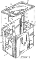
- Figure 1 is an exploded perspective view of the box and cover without the reel being mounted therein;
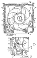
- Figure 2 is an elevation cross sectional view of the box with the reel mounted therein;
- Figure 3 is an enlarged cross-sectional view taken along lines 3-3 of figure 2;
- Figure 4 is an elevation cross sectional view of the box, brake device and reel taken along lines 4-4 of figure 2;
- Figure 5 is an enlarged cross-sectional view of the lower left corner area of figure 4;
- Figure 6 is a perspective view of the hub with one integral side plate of the reel;
- Figure 7 is a perspective view of the other side plate of the reel;
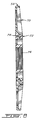
- Figure 8 is a cross-sectional view of the side plate taken along lines 8-8 of figure 7; and
- Figure 9 is a perspective view of the brake device.
- Referring to figure 1, there is shown a box, generally denoted 10, defining a parallelepiped body having a
bottom 12,sidewalls removable cover 22.Sidewalls elongated openings elongated opening 28 andpointed slot 29 are provided onsidewall 20, the functions of which will be described further. -
Walls areas legs cover 22. Eachleg concave extremity cover 22 has a pair ofopposite troughs corresponding openings sidewalls - Referring to figures 2 and 4, there is shown a reel, generally denoted 50, on which is wound a supply of wire, cable or the like. A strand may be seen as 52 egressing from opening 28 on the
sidewall 20 of the box. Thereel 50 consists of ahub 54 to which is integrally formed aside plate 56 at one side thereof. At the other end of the hub is threadedly mounted asecond side plate 58. - Referring to figure 6, the
side plate 56 includes anannular wall 60, the rear face of which displays a series ofcircumferential elements 62, each constituted by a arc-shaped face 64 extending betweenfaces 66 which are tangent thereto. The opposite end of thehub 54 has a threadedportion 68 on which is threadedly mounted theside plate 58. - Referring to figures 7 and 8, the
opposite side plate 58 comprises an outerannular portion 70 circumferentially and concentrically mounted about an innerannular portion 72. The engagement between the two portions is accomplished through a tongue andgroove arrangement 74, thereby allowing free rotation of theouter portion 70 relative to theinner portion 72, the latter having a threadedcore 76 adapted to be engaged with threadedportion 68 of the hub. - As can been seen in figures 2 and 3, the
opposite ends portions sidewalls opposite ends walls concave extremities legs cover 22. - Referring to figures 4, 5 and 9, also mounted within the box is a brake device, generally denoted 100, which has a
cylindrical portion 102 and a pair of projectingmembers member appropriate supports 110 mounted to thebottom 12 of the box as well as to eachopposite sidewall member resilient elements sidewall 16 as illustrated in figures 4 and 5. - The
cylindrical surface 102 acts as a sliding surface for the passage of the strand of wire orcable 52 thereon as it is unwound from the reel prior to passing through theopening 28. The projectingmember 106 has a first surface 106a adapted to slide along thesurface 64 on the side plate of the reel and a secondabutting surface 106b adapted to contact thetangent surface 66 to stop the reel from rotating. As illustrated in figures 4 and 5, thebrake device 100 has its abuttingsurface 106b contacting surface 66; hence, rotation of thereel 58 in a counterclockwise direction as indicated byarrow 122 is prevented. A pull exerted on thestrand 52 in the direction indicated byarrow 120, as it slides on thecylindrical surface 102, causes the brake device to pivot at theside extensions 108 thereby distancingsurface 106b fromsurface 66 of the reel. This pivotal action also causes a further compression of theresilient elements wall 16. As soon as the external pull is released, the resiliency of thecompressed elements pivots 108, thus causing surface 106a of the brake device to slide along the next slidingsurface 64 of the reel until theabutting surface 106b contacts thenext stop surface 66. Hence, the construction of the brake device is such as to enable an unwinding rotation of the reel in the direction indicated byarrow 122. However, immediate stoppage of rotation is achieved as soon as no pull is exerted on the strand. - The sudden stoppage of the reel causes the supply of wire on the reel to slide on the hub in the rotational direction. Normally, this would result in a further tightening engagement of the threaded
portion 76 of the side plate onto the threadedportions 68 of the hub. However, the particular construction of theside plate 58 with its freelyrotatable portion 70 allows the latter to follow the incremental movement of the hub supply, thus avoiding further tightening between the engaged threaded portions. - The
side extension 30 onwall 14 has anopening 126, thus giving access to a tool to be inserted and engage aslot 128 at theextremity 80 of the reel; this allows the user to rewind that portion of the strand outside the box which is not used without removing the cover. Once the free end of the strand is adjacent the box, it can be tightly squeezed into theslot 29 in thesidewall 20 of the box. - A
slot 130 is provided oncover 22 to give an indication to the operator the amount of wire left on the reel; graduation marks could also be provided adjacent to the slot to indicate more accurate amount of the wire left.
Claims (19)
- A device for dispensing wire, cable, or the like, comprising :a) a box (10) defining a parallelepiped body having a bottom (12), side walls (14, 16, 18, 20) and a removable cover (22); said box displaying an opening (28) for the egress therefrom of a strand (52) of wire, cable or the like;b) a reel (50) rotatably mounted in said box; said reel consisting of a hub (54) and opposite side plates (56,58) confining therebetween a wound supply of wire, cable, or the like to be dispensed;c) a brake device (100) securely mounted in said box; said brake device having a pivotable portion (102) adapted to be slidingly contacted by said strand (52) prior to egressing from said box;d) inter-engageable means (106b ; 66) on said brake device (100) and on one (56) of said side plates cooperating to stop rotation of said reel; ande) resilient means (112, 114) having a first portion secured to said brake device (100) and a second portion contacting a side wall (16) of said box (10), said second portion being resiliently compressed against said side wall (16) to urge said inter-engageable means in inter-engagement;said pivotable portion (102) of said brake device (100) being pivoted by a pull on said strand outside said box (10) thereby freeing said inter-engageable means from engagement with one another and allowing said reel (50) to rotate in a dispensing direction; said resilient means (112, 114) returning said inter-engageable means in engagement upon release of said pull to thereby block rotation of said reel (50).
- A device as defined in claim 1, wherein said inter-engageable means on said one side palte (56) consist of a series of spaced abutting surfaces (66) disposed peripherally on said one side plate to be contacted by the inter-engageable means (106b) on said brake device.
- A device as defined in claim 2, wherein said one side plate (56) further includes inwardly curved sliding surfaces (64) extending between said abutting surfaces (66).
- A device as defined in claim 1, wherein said hub (54) and said one side plate (56) define an integrally formed body.
- A device as defined in claim 4, wherein said hub (54) includes at one end opposite to said one side plate (56) a threaded portion (68).
- A device as defined in claim 5, wherein the other (58) of said side plates is threadedly mounted onto said threaded portion (68) of said hub (54).
- A device as defined in claim 6, wherein said other side plate (58) consists of two concentrically mounted portions (70, 72) including an inner annular portion (72) theradedly engaged with said hub (54) and an outer annular portion (70) freely mounted to said inner portion (72).
- A device as defined in claim 1, wherein two opposite side walls (14,18) of said box (10) each include support means (30, 32) to rotatably receive thereon opposite ends (80, 82) of said hub (54).
- A device as defined in claim 8, wherein said cover (22) has means (34, 36) downwardly extending in said box (10) adjacent said opposite side walls (14, 18) to confine said reel (50) in said box.
- A device as defined in claim 9, wherein said downwardly extending means consist of a pair of legs (34, 36) each having a lower end (38, 40) configured to extend over a corresponding portion of said end (80, 82) of said hub (54).
- A device as defined in claim 10, wherein said opposite side walls (14, 18) of said box (10) have recessed areas (30, 32) to receive therein said pair of legs (34, 36).
- A device as defined in claim 11, wherein one (30) of said recessed areas (30, 32) includes a wall opening (126) to provide access to one end (80) of said hub (54); said one end of said hub having tool engaging means (128) to receive a tool for manually rotating said reel (50) from outside said box (10).
- A device as defined in claim 1, wherein said resilient means consist of a pair of flexible elongated members (112, 114) having one end secured to said brake device (100) and the opposite end adapted to contact a side wall (16) of said box.
- A device as defined in claim 13, wherein said pivotable portion of said brake device (100) includes a cylindrical body (102) defining a sliding surface to allow sliding passage of said strand (52) thereon.
- A device as defined in claim 14, wherein said inter-engageable means on said brake device consist of projecting means (106b) on said cylindrical body (102) adapted to contact said inter-engageable means (66) on said one side plate of said reel.
- A device as defined in claim 1, wherein said cover (22) includes means (42, 44) cooperating with means (46, 48) on opposite side walls (14, 18) for locking said cover (22) to said box (10).
- A device as defined in claim 1, wherein said cover (22) includes an opening (130) to provide visual indication of the wire, cable or the like remaining on said reel (50) in said box (10).
- A device as defined in claim 1, wherein a pair of opposite side walls (16, 20) of said box (10) each include an opening (24, 26) defining a handle allowing said box (10) to be carried.
- A device as defined in claim 1, wherein one (20) of said side walls includes the opening (28) allowing egress of the strand (52) of wire, cable or the like, and said one side wall (20) further includes slot means (29) to fix one free end of the strand (52) of wire, cable or the like.
Applications Claiming Priority (2)
| Application Number | Priority Date | Filing Date | Title |
|---|---|---|---|
| CA2068828 | 1992-05-15 | ||
| CA002068828A CA2068828C (en) | 1992-05-15 | 1992-05-15 | Device for dispensing wire, cable or the like |
Publications (3)
| Publication Number | Publication Date |
|---|---|
| EP0570302A2 EP0570302A2 (en) | 1993-11-18 |
| EP0570302A3 EP0570302A3 (en) | 1995-06-14 |
| EP0570302B1 true EP0570302B1 (en) | 1997-03-05 |
Family
ID=4149848
Family Applications (1)
| Application Number | Title | Priority Date | Filing Date |
|---|---|---|---|
| EP93401251A Expired - Lifetime EP0570302B1 (en) | 1992-05-15 | 1993-05-14 | A device for dispensing wire, cable or the like |
Country Status (5)
| Country | Link |
|---|---|
| US (1) | US5261625A (en) |
| EP (1) | EP0570302B1 (en) |
| AT (1) | ATE149473T1 (en) |
| CA (1) | CA2068828C (en) |
| DE (1) | DE69308371T2 (en) |
Families Citing this family (41)
| Publication number | Priority date | Publication date | Assignee | Title |
|---|---|---|---|---|
| US5417232A (en) * | 1992-09-25 | 1995-05-23 | Ballard; Larry N. | Multiple lock dental floss holder and spool enclosure assembly therefor |
| USRE40351E1 (en) * | 1996-07-24 | 2008-06-03 | Lincoln Global, Inc. | Mechanism for braking the unwinding of a bundle of metallic wire housed in a drum |
| IT1286954B1 (it) * | 1996-07-24 | 1998-07-24 | C I F E S P A | Dispositivo per la frenatura dello svolgimento di filo metallico in matassa alloggiato in fusto |
| WO1998004489A1 (en) * | 1996-07-31 | 1998-02-05 | Italiana Conduttori S.R.L. | Cable spool holder and spool to be used therewith |
| FR2752825B1 (en) * | 1996-09-03 | 1998-10-16 | Telecommunications Sa | CABLE CONDITIONING DEVICE |
| FR2775671B1 (en) | 1998-03-09 | 2000-05-19 | Poujoulat Sa | PACKAGING OF A FLEXIBLE TUBULAR ELEMENT |
| US6367725B1 (en) | 2000-10-12 | 2002-04-09 | Brian S. Goodwin | Wire spooler/distributor |
| US6648141B2 (en) | 2001-09-04 | 2003-11-18 | Lincoln Global, Inc. | Packaging for containing and dispensing large quantities of wire |
| US6547176B1 (en) * | 2002-06-04 | 2003-04-15 | Air Liquide Canada Inc. | Wire unwinding controller |
| US20040255810A1 (en) * | 2003-03-28 | 2004-12-23 | O'brien John P. | Detonating cord inventory control marking system |
| US6913145B2 (en) * | 2003-04-15 | 2005-07-05 | Lincoln Global, Inc. | Welding wire container with ribbed walls and a mating retainer ring |
| US7147102B2 (en) * | 2004-01-21 | 2006-12-12 | Silverbrook Research Pty Ltd | Consumer tote with core |
| US7222734B2 (en) * | 2004-07-15 | 2007-05-29 | Lincoln Global, Inc. | Welding wire package with lifting strap |
| US7748660B2 (en) | 2007-06-22 | 2010-07-06 | Ofs Fitel, Llc | Fiber optic rapid spooling tool |
| DK2288469T3 (en) | 2008-05-27 | 2013-07-08 | Awds Technologies Srl | Wiring System |
| DK2174741T3 (en) | 2008-10-07 | 2012-10-01 | Sidergas Spa | Lid for welding wire container |
| US8674263B2 (en) | 2009-07-20 | 2014-03-18 | Awds Technologies Srl | Wire guiding liner, in particular a welding wire liner, with biasing means between articulated guiding bodies |
| US8393467B2 (en) | 2009-08-21 | 2013-03-12 | Sidergas Spa | Retainer for welding wire container, having fingers and half-moon shaped holding tabs |
| US8235211B2 (en) * | 2009-08-21 | 2012-08-07 | Sidergas Spa | Retainer for welding wire container, having fingers and half-moon shaped holding tabs |
| US8389901B1 (en) | 2010-05-27 | 2013-03-05 | Awds Technologies Srl | Welding wire guiding liner |
| AU2010257221B2 (en) * | 2010-12-15 | 2016-10-06 | Commscope Technologies Llc | Assembly for dispensing cable |
| US8770438B2 (en) * | 2011-04-18 | 2014-07-08 | Daniel A. Cahill | Portable containers for zip ties |
| US9601880B2 (en) * | 2011-11-08 | 2017-03-21 | Ortronics, Inc. | Cable assemblies and associated systems and methods |
| US8967520B2 (en) * | 2011-11-22 | 2015-03-03 | Lincoln Global, Inc. | Wire retaining ring for a welding system |
| US8882018B2 (en) * | 2011-12-19 | 2014-11-11 | Sidergas Spa | Retainer for welding wire container and welding wire container with retainer |
| WO2013187964A1 (en) * | 2012-04-06 | 2013-12-19 | Optical Cable Corporation | Fiber optic/electrical cable reel cartridge system |
| US10294065B2 (en) | 2013-06-06 | 2019-05-21 | Sidergas Spa | Retainer for a welding wire container and welding wire container |
| US10343231B2 (en) | 2014-05-28 | 2019-07-09 | Awds Technologies Srl | Wire feeding system |
| US10010962B1 (en) | 2014-09-09 | 2018-07-03 | Awds Technologies Srl | Module and system for controlling and recording welding data, and welding wire feeder |
| US10350696B2 (en) | 2015-04-06 | 2019-07-16 | Awds Technologies Srl | Wire feed system and method of controlling feed of welding wire |
| US9975728B2 (en) | 2015-09-10 | 2018-05-22 | Sidergas Spa | Wire container lid, wire container and wire feeding system |
| US9950857B1 (en) | 2016-10-17 | 2018-04-24 | Sidergas Spa | Welding wire container |
| CN109119928B (en) * | 2017-02-11 | 2020-03-27 | 烟台知兴知识产权咨询服务有限公司 | Power cable conveyer |
| CN107585640A (en) * | 2017-08-15 | 2018-01-16 | 国家电网公司 | A kind of electric power first-aid cable winding apparatus |
| CN110589629A (en) * | 2019-09-11 | 2019-12-20 | 武汉无限星云信息技术有限公司 | Line case for internet data center machine room |
| US11174121B2 (en) | 2020-01-20 | 2021-11-16 | Awds Technologies Srl | Device for imparting a torsional force onto a wire |
| US11278981B2 (en) | 2020-01-20 | 2022-03-22 | Awds Technologies Srl | Device for imparting a torsional force onto a wire |
| WO2022154970A1 (en) | 2021-01-15 | 2022-07-21 | Commscope Technologies Llc | Adjustable reloadable cable reel |
| FI4046950T3 (en) * | 2021-02-19 | 2024-03-19 | Nexans | Cable packaging assembly for storing and unspooling of an electric cable |
| WO2022187108A1 (en) | 2021-03-02 | 2022-09-09 | Commscope Technologies Llc | Adjustable reloadable cable reel |
| US20250066155A1 (en) * | 2023-08-24 | 2025-02-27 | Anderson Travis Holdings, LLC | Reel arrangement and locking mechanism |
Family Cites Families (24)
| Publication number | Priority date | Publication date | Assignee | Title |
|---|---|---|---|---|
| US248261A (en) * | 1881-10-11 | Take-up and tension for grain-binders | ||
| US209144A (en) * | 1878-10-22 | Improvement in tension-wheels | ||
| US1354598A (en) * | 1917-10-20 | 1920-10-05 | Hallie V D Crumbaugh | Thread-box |
| US1474580A (en) * | 1923-02-19 | 1923-11-20 | George L Clark | Electric-wiring machine |
| GB286859A (en) * | 1927-02-18 | 1928-03-15 | Henleys Telegraph Works Co Ltd | Improvements in or relating to drums for electric cables and the like |
| US1908073A (en) * | 1929-05-10 | 1933-05-09 | Gerrard Co Inc | Wire reel |
| US3069107A (en) * | 1958-12-01 | 1962-12-18 | Continental Copper & Steel Ind | Reel play-off stand |
| US3027003A (en) * | 1959-09-23 | 1962-03-27 | Phillips Electrical Company Lt | Cable reel carton device |
| US3150769A (en) * | 1962-09-06 | 1964-09-29 | South River Metal Products Co | Wire packaging and handling device |
| DE1486614A1 (en) * | 1964-08-14 | 1969-07-10 | South River Metal Products Co | Wire packing and handling device |
| US3680810A (en) * | 1971-02-16 | 1972-08-01 | Saxton Products Inc | Pay-out container for spooled wire and analogous elongated elements |
| CA970749A (en) * | 1972-05-25 | 1975-07-08 | Windings | Package of flexible material for twistless payout and method of making such package |
| US3796392A (en) * | 1972-11-06 | 1974-03-12 | Bell Telephone Labor Inc | Brake for a wire reel |
| CA1010831A (en) * | 1974-06-17 | 1977-05-24 | Leon Kowalski | Azimuth seeking reeled primer cord dispenser |
| US3982712A (en) * | 1975-11-28 | 1976-09-28 | Bassett Eugene E | Coil dispenser |
| FR2351897A1 (en) * | 1976-05-20 | 1977-12-16 | Callot Jean Pol | Wire unwinding drum used in fence making - is fitted with automatic brake operating from jockey pulley |
| US4077586A (en) * | 1976-05-26 | 1978-03-07 | General Cable Corporation | Drop wire payout apparatus |
| US4108397A (en) * | 1977-05-16 | 1978-08-22 | Hauck Dorothy M | Caddy for knitting and crocheting yarn |
| CA1071605A (en) * | 1977-10-03 | 1980-02-12 | Ronald E. Zajac | Tube for inner end feedout of flexible material and package utilizing the same |
| US4124176A (en) * | 1977-12-16 | 1978-11-07 | Western Electric Company | Self-tensioning reel |
| US4126281A (en) * | 1978-03-13 | 1978-11-21 | Young Bernard L | Skeiner |
| US4537366A (en) * | 1983-07-13 | 1985-08-27 | Swenson Kirk A | Roll container |
| BR8500013A (en) * | 1985-01-04 | 1985-07-02 | Pirelli Brasil | DEVELOPER MODULE FOR STACKING SPOOLS CONTAINING ELECTRIC CONDUCTORS |
| CA1260445A (en) * | 1989-01-09 | 1989-09-26 | Bernard Letourneau | Wire dispensing spool and casing |
-
1992
- 1992-05-15 CA CA002068828A patent/CA2068828C/en not_active Expired - Fee Related
- 1992-05-29 US US07/891,288 patent/US5261625A/en not_active Expired - Fee Related
-
1993
- 1993-05-14 EP EP93401251A patent/EP0570302B1/en not_active Expired - Lifetime
- 1993-05-14 DE DE69308371T patent/DE69308371T2/en not_active Expired - Fee Related
- 1993-05-14 AT AT93401251T patent/ATE149473T1/en not_active IP Right Cessation
Also Published As
| Publication number | Publication date |
|---|---|
| DE69308371T2 (en) | 1997-10-23 |
| CA2068828C (en) | 1998-12-22 |
| EP0570302A3 (en) | 1995-06-14 |
| US5261625A (en) | 1993-11-16 |
| EP0570302A2 (en) | 1993-11-18 |
| DE69308371D1 (en) | 1997-04-10 |
| ATE149473T1 (en) | 1997-03-15 |
| CA2068828A1 (en) | 1993-11-16 |
Similar Documents
| Publication | Publication Date | Title |
|---|---|---|
| CA2068828C (en) | Device for dispensing wire, cable or the like | |
| EP0922003B1 (en) | Cable spool holder and spool to be used therewith | |
| JPH0622684Y2 (en) | Tape dispenser | |
| US5509616A (en) | Retractable chalk line device | |
| AU2002219917B2 (en) | Hand-held adhesive tape dispenser | |
| EP1628889B1 (en) | A cap for palletised loads | |
| US5551647A (en) | Cable storage and feeding device | |
| CA1134769A (en) | Ribbon cartridge and method | |
| US4195794A (en) | Reel holder with drag | |
| US4787168A (en) | Fishing line dispenser and display package | |
| JPS60137766A (en) | Dispenser simultaneously executing distribution and cutting | |
| EP0698368A1 (en) | Apparatus for supporting a coreless paper roll and for impeding rotation of the roll during paper dispensing | |
| CA2004353A1 (en) | Apparatus for the application of an adhesive film | |
| US5465917A (en) | Welding wire dispenser with adjustable brake | |
| US3589634A (en) | Multiroll surveyor ribbon dispenser | |
| US4244503A (en) | Dispenser for flexible material | |
| WO1998052811A1 (en) | Wheeled device | |
| CA1205051A (en) | Dispenser for tape rolls | |
| US9670028B1 (en) | Trigger operated brake for handheld tape dispenser including a barbed spool holder | |
| US5826817A (en) | Self dispensing and storage device for flexible tubing | |
| US5938070A (en) | Self-adhesive stamp dispenser | |
| US5600934A (en) | Device for applying a closing strip | |
| US20070210131A1 (en) | Enclosed spool | |
| EP0310291B1 (en) | Apparatus for dispensing plastics stretch film | |
| US5052420A (en) | Tooth cleaner device for retention of reel means carrying a spool of strings |
Legal Events
| Date | Code | Title | Description |
|---|---|---|---|
| PUAI | Public reference made under article 153(3) epc to a published international application that has entered the european phase |
Free format text: ORIGINAL CODE: 0009012 |
|
| AK | Designated contracting states |
Kind code of ref document: A2 Designated state(s): AT BE CH DE DK ES FR GB GR IE IT LI LU MC NL PT SE |
|
| PUAL | Search report despatched |
Free format text: ORIGINAL CODE: 0009013 |
|
| AK | Designated contracting states |
Kind code of ref document: A3 Designated state(s): AT BE CH DE DK ES FR GB GR IE IT LI LU MC NL PT SE |
|
| 17P | Request for examination filed |
Effective date: 19951128 |
|
| 17Q | First examination report despatched |
Effective date: 19960130 |
|
| GRAG | Despatch of communication of intention to grant |
Free format text: ORIGINAL CODE: EPIDOS AGRA |
|
| GRAG | Despatch of communication of intention to grant |
Free format text: ORIGINAL CODE: EPIDOS AGRA |
|
| GRAH | Despatch of communication of intention to grant a patent |
Free format text: ORIGINAL CODE: EPIDOS IGRA |
|
| GRAH | Despatch of communication of intention to grant a patent |
Free format text: ORIGINAL CODE: EPIDOS IGRA |
|
| GRAA | (expected) grant |
Free format text: ORIGINAL CODE: 0009210 |
|
| AK | Designated contracting states |
Kind code of ref document: B1 Designated state(s): AT BE CH DE DK ES FR GB GR IE IT LI LU MC NL PT SE |
|
| PG25 | Lapsed in a contracting state [announced via postgrant information from national office to epo] |
Ref country code: NL Free format text: LAPSE BECAUSE OF FAILURE TO SUBMIT A TRANSLATION OF THE DESCRIPTION OR TO PAY THE FEE WITHIN THE PRESCRIBED TIME-LIMIT Effective date: 19970305 Ref country code: LI Effective date: 19970305 Ref country code: IT Free format text: LAPSE BECAUSE OF FAILURE TO SUBMIT A TRANSLATION OF THE DESCRIPTION OR TO PAY THE FEE WITHIN THE PRE;WARNING: LAPSES OF ITALIAN PATENTS WITH EFFECTIVE DATE BEFORE 2007 MAY HAVE OCCURRED AT ANY TIME BEFORE 2007. THE CORRECT EFFECTIVE DATE MAY BE DIFFERENT FROM THE ONE RECORDED.SCRIBED TIME-LIMIT Effective date: 19970305 Ref country code: GR Free format text: LAPSE BECAUSE OF FAILURE TO SUBMIT A TRANSLATION OF THE DESCRIPTION OR TO PAY THE FEE WITHIN THE PRESCRIBED TIME-LIMIT Effective date: 19970305 Ref country code: ES Free format text: THE PATENT HAS BEEN ANNULLED BY A DECISION OF A NATIONAL AUTHORITY Effective date: 19970305 Ref country code: DK Effective date: 19970305 Ref country code: CH Effective date: 19970305 Ref country code: BE Effective date: 19970305 Ref country code: AT Effective date: 19970305 |
|
| REF | Corresponds to: |
Ref document number: 149473 Country of ref document: AT Date of ref document: 19970315 Kind code of ref document: T |
|
| REG | Reference to a national code |
Ref country code: CH Ref legal event code: EP |
|
| REF | Corresponds to: |
Ref document number: 69308371 Country of ref document: DE Date of ref document: 19970410 |
|
| REG | Reference to a national code |
Ref country code: IE Ref legal event code: FG4D Free format text: 72311 |
|
| PG25 | Lapsed in a contracting state [announced via postgrant information from national office to epo] |
Ref country code: LU Free format text: LAPSE BECAUSE OF NON-PAYMENT OF DUE FEES Effective date: 19970514 Ref country code: IE Free format text: LAPSE BECAUSE OF NON-PAYMENT OF DUE FEES Effective date: 19970514 |
|
| PG25 | Lapsed in a contracting state [announced via postgrant information from national office to epo] |
Ref country code: SE Effective date: 19970605 Ref country code: PT Effective date: 19970605 |
|
| ET | Fr: translation filed | ||
| NLV1 | Nl: lapsed or annulled due to failure to fulfill the requirements of art. 29p and 29m of the patents act | ||
| REG | Reference to a national code |
Ref country code: CH Ref legal event code: PL |
|
| PG25 | Lapsed in a contracting state [announced via postgrant information from national office to epo] |
Ref country code: MC Effective date: 19971130 |
|
| PLBE | No opposition filed within time limit |
Free format text: ORIGINAL CODE: 0009261 |
|
| STAA | Information on the status of an ep patent application or granted ep patent |
Free format text: STATUS: NO OPPOSITION FILED WITHIN TIME LIMIT |
|
| 26N | No opposition filed | ||
| PGFP | Annual fee paid to national office [announced via postgrant information from national office to epo] |
Ref country code: GB Payment date: 19980508 Year of fee payment: 6 |
|
| PGFP | Annual fee paid to national office [announced via postgrant information from national office to epo] |
Ref country code: FR Payment date: 19980526 Year of fee payment: 6 |
|
| PGFP | Annual fee paid to national office [announced via postgrant information from national office to epo] |
Ref country code: DE Payment date: 19980630 Year of fee payment: 6 |
|
| PG25 | Lapsed in a contracting state [announced via postgrant information from national office to epo] |
Ref country code: GB Free format text: LAPSE BECAUSE OF NON-PAYMENT OF DUE FEES Effective date: 19990514 |
|
| GBPC | Gb: european patent ceased through non-payment of renewal fee |
Effective date: 19990514 |
|
| PG25 | Lapsed in a contracting state [announced via postgrant information from national office to epo] |
Ref country code: FR Free format text: LAPSE BECAUSE OF NON-PAYMENT OF DUE FEES Effective date: 20000131 |
|
| PG25 | Lapsed in a contracting state [announced via postgrant information from national office to epo] |
Ref country code: DE Free format text: LAPSE BECAUSE OF NON-PAYMENT OF DUE FEES Effective date: 20000301 |
|
| REG | Reference to a national code |
Ref country code: FR Ref legal event code: ST |