EP0570163A2 - Systems for optically inspecting cylindrical surfaces - Google Patents
Systems for optically inspecting cylindrical surfaces Download PDFInfo
- Publication number
- EP0570163A2 EP0570163A2 EP93303544A EP93303544A EP0570163A2 EP 0570163 A2 EP0570163 A2 EP 0570163A2 EP 93303544 A EP93303544 A EP 93303544A EP 93303544 A EP93303544 A EP 93303544A EP 0570163 A2 EP0570163 A2 EP 0570163A2
- Authority
- EP
- European Patent Office
- Prior art keywords
- image
- cigarette
- drum
- video camera
- illumination
- Prior art date
- Legal status (The legal status is an assumption and is not a legal conclusion. Google has not performed a legal analysis and makes no representation as to the accuracy of the status listed.)
- Granted
Links
Images


Classifications
-
- G—PHYSICS
- G01—MEASURING; TESTING
- G01N—INVESTIGATING OR ANALYSING MATERIALS BY DETERMINING THEIR CHEMICAL OR PHYSICAL PROPERTIES
- G01N21/00—Investigating or analysing materials by the use of optical means, i.e. using sub-millimetre waves, infrared, visible or ultraviolet light
- G01N21/84—Systems specially adapted for particular applications
- G01N21/88—Investigating the presence of flaws or contamination
- G01N21/95—Investigating the presence of flaws or contamination characterised by the material or shape of the object to be examined
- G01N21/952—Inspecting the exterior surface of cylindrical bodies or wires
-
- A—HUMAN NECESSITIES
- A24—TOBACCO; CIGARS; CIGARETTES; SIMULATED SMOKING DEVICES; SMOKERS' REQUISITES
- A24C—MACHINES FOR MAKING CIGARS OR CIGARETTES
- A24C5/00—Making cigarettes; Making tipping materials for, or attaching filters or mouthpieces to, cigars or cigarettes
- A24C5/32—Separating, ordering, counting or examining cigarettes; Regulating the feeding of tobacco according to rod or cigarette condition
- A24C5/34—Examining cigarettes or the rod, e.g. for regulating the feeding of tobacco; Removing defective cigarettes
- A24C5/3412—Examining cigarettes or the rod, e.g. for regulating the feeding of tobacco; Removing defective cigarettes by means of light, radiation or electrostatic fields
-
- B—PERFORMING OPERATIONS; TRANSPORTING
- B07—SEPARATING SOLIDS FROM SOLIDS; SORTING
- B07C—POSTAL SORTING; SORTING INDIVIDUAL ARTICLES, OR BULK MATERIAL FIT TO BE SORTED PIECE-MEAL, e.g. BY PICKING
- B07C5/00—Sorting according to a characteristic or feature of the articles or material being sorted, e.g. by control effected by devices which detect or measure such characteristic or feature; Sorting by manually actuated devices, e.g. switches
- B07C5/34—Sorting according to other particular properties
- B07C5/342—Sorting according to other particular properties according to optical properties, e.g. colour
- B07C5/3422—Sorting according to other particular properties according to optical properties, e.g. colour using video scanning devices, e.g. TV-cameras
-
- G—PHYSICS
- G01—MEASURING; TESTING
- G01N—INVESTIGATING OR ANALYSING MATERIALS BY DETERMINING THEIR CHEMICAL OR PHYSICAL PROPERTIES
- G01N21/00—Investigating or analysing materials by the use of optical means, i.e. using sub-millimetre waves, infrared, visible or ultraviolet light
- G01N21/84—Systems specially adapted for particular applications
- G01N21/88—Investigating the presence of flaws or contamination
- G01N21/8851—Scan or image signal processing specially adapted therefor, e.g. for scan signal adjustment, for detecting different kinds of defects, for compensating for structures, markings, edges
- G01N2021/8887—Scan or image signal processing specially adapted therefor, e.g. for scan signal adjustment, for detecting different kinds of defects, for compensating for structures, markings, edges based on image processing techniques
-
- G—PHYSICS
- G01—MEASURING; TESTING
- G01N—INVESTIGATING OR ANALYSING MATERIALS BY DETERMINING THEIR CHEMICAL OR PHYSICAL PROPERTIES
- G01N2201/00—Features of devices classified in G01N21/00
- G01N2201/10—Scanning
- G01N2201/102—Video camera
Definitions
- This invention relates to systems for optically inspecting cylindrical surfaces such as the cylindrical surfaces of cigarettes.
- the cylindrical surface may be defective due to a piece of tobacco stem piercing the paper, an imperfection in the way the filter has been joined to the remainder of the cigarette (including the possible complete absence of the intended filter), an imperfectly formed side seal which leaves some of the tobacco visible, a discoloration of the paper, etc.
- Tobacco smoking articles such as cigarettes and cigars, are made into rods on machines which take cut filler that is formed into a continuous rod of tobacco, and encircles the tobacco with a continuous ribbon of paper which is glued and heat-sealed.
- the continuous tobacco rod is formed and sealed in the making machine and then proceeds to another processing machine, such as a tipper.
- the tipper attaches a filter plug cut to the appropriate length between two tobacco rods.
- the tipper applies glue and wraps tipping paper around the filter segment and a portion of the tobacco rods. This creates a double cigarette length.
- the two cigarettes are then cut and oriented into a single row.
- a tipper as described is shown, for example, in U.S. Patent No. 3,527,234 to Hinzmann. It is the completed cigarette that is inspected for unsatisfactory conditions.
- Still other cigarette inspection systems use more than one drum to create more than one inspection zone.
- U.S. Patent No. 4,639,592 to Heitman passes cigarettes before optical inspection devices located at certain points along a predetermined path. The path requires at least two vacuum drums each to expose one side of the cigarette. Note that Heitman specifically prefers to not mechanically rotate the cigarette.
- Great British Patent No. 2,221,029 teaches a similar method.
- any successful inspection system for products such as cigarettes must be extremely fast in order to keep pace with the high speeds at which such products are typically made. For example, it is now common for a single cigarette making machine to make cigarettes at rates approaching 10,000 per minute. A successful cigarette inspection system must also be able to inspect for relatively small and/or subtle defects (e.g., a hole as small as about .5 millimeter in diameter or a minor discoloration of the cigarette paper).
- apparatus for optically inspecting substantially the entire cylindrical surface of a cylindrical object comprising: a first support for supporting the object so that a first side of the said surface of the object is exposed; a first image former for forming a first image of the said first side; means for exposing a second side of the said surface of the object, the first and second sides together including the whole of the said surface; a second image former for forming a second image of the said second side, the first and second sides together including the entire cylindrical surface of the object.
- a method for optically inspecting substantially the entire cylindrical surface of a cylindrical object comprising: supporting the object on a support surface; inspecting a first portion of the cylindrical surface of the object to generate an image; rotating the object through 180°; inspecting a second portion of the cylindrical surface of the object, the first and second portions together including the entire cylindrical surface of the object to generate another image; analyzing each image to determine whether or not they meet a predetermined criterion; and rejecting the object if the predetermined criterion is not met.
- the invention provides cylindrical surface inspection systems in which the object having the cylindrical surface is first supported (e.g., on the surface of a first rotating drum) so that one side of the object (preferably including at least half of the circumference of the cylinder) is exposed for optical inspection along a substantial length of the object.
- the exposed portion of the surface is illuminated by light from two linear light sources. These two light sources are aligned with the longitudinal axis of the cylindrical surface and are spaced apart by a relatively large distance circumferentially of the cylindrical surface so that collectively they preferably illuminate at least half of the circumference of the surface. Light reflected from the surface in two radially different directions is then used to form images of the surface.
- the two reflected light directions are preferably intermediate the directions from which the light arrives from the two light sources.
- the two reflected light directions are preferably sufficiently widely spaced circumferentially of the cylindrical surface so that collectively they provide image information regarding at least half the circumference of the surface.
- Optical components are preferably provided to direct the light reflected from the above-mentioned two directions to a single camera to reduce the number of cameras required.
- the support for the object is changed to expose the other side for optical inspection.
- the object may be transferred from the surface of the above-mentioned first rotating drum to the surface of a second rotating drum. Again, preferably at least half the circumference of the cylinder is exposed. This newly exposed portion of the surface is illuminated and imaged in the same way that the first side is illuminated and imaged.
- a second camera (aided by optical components similar to those mentioned above in connection with the first camera) receives the reflected light from the two directions associated with the second side of the object.
- each partial image of the cylindrical surface is analyzed to detect any defects in appearance.
- each image is subdivided into a plurality of regions, each of which is aligned with the longitudinal axis of the cylindrical surface, and each of which is only a relatively small fraction of the dimension of the image transverse to that longitudinal axis.
- the image information in each of these regions is compared to expected information for that region (e.g., on an absolute or relative basis). Aligning the regions with the longitudinal axis of the cylindrical surface and confining each region to a small fraction of the circumference of the cylinder increases the sensitivity of the system to possible variations in the illumination level of the object in the circumferential direction.
- any object having any unacceptable image is identified and preferably rejected so that it does not continue on for the further processing to which acceptable objects are subjected.
- This system also preferably includes means for displaying the images of the objects, especially the images of defective objects, so the operator of the system can observe the nature of any defects.
- the system may also display information regarding such statistics as the number and/or percentage of defective objects encountered.
- the invention provides in a second aspect a machine vision system comprising at least two-dimensional video cameras to inspect cigarettes at two positions on a single rolling drum, preferably as part of the tipper.
- a machine vision system comprising at least two-dimensional video cameras to inspect cigarettes at two positions on a single rolling drum, preferably as part of the tipper.
- the first rolling block attaches a filter plug to the tobacco rods, as part of the standard tipping operation of the tipper.
- a first two-dimensional video camera Located after the first rolling block is a first two-dimensional video camera to inspect nearly the entire first half of the completed single- or double-length cigarette.
- a second rolling block is then provided to roll the cigarette approximately 180°.
- a second two-dimensional video camera Located after the second rolling block is a second two-dimensional video camera to inspect nearly the entire second half of the cigarette.
- a rolling drum can be provided after the tipper to provide the space needed for a first inspection, rolling the completed cigarette and then a second inspection.
- This drum could also be located just at the end of the tipper.
- the vision system determines, from the information provided by the video cameras, whether the cigarette meets the preset characteristics for a completed cigarette. If the cigarette does not meet those characteristics, the cigarette is removed from the cigarette manufacturing system by a delivery/reject drum.
- the delivery/reject drum is located directly after the rolling drum and may be conventional.
- the second aspect of the invention provides a compact, efficient system for inspecting completed cigarettes at the high speeds of production encountered in today's modern manufacturing systems.
- FIG. 1 shows the final portion 100 of a conventional Max S cigarette tipping machine which has been modified to include apparatus according to the first aspect of the present Max S machine is manufactured by Hauni-Werke Korber & Co. KG. of Hamburg, Germany.
- the fabrication of the cigarettes is complete and it remains only to inspect them. Accordingly, as is conventional, the finished cigarettes are deposited one after another on conventional rotating inspection drum 110.
- Inspection drum 110 has a plurality of circumferentially spaced, axially extending flutes 112 on its outer surface.
- Each flute receives one cigarette 12, and the cigarette is held in the flute by reduced pressure ("vacuum") which is communicated to the bottom of the flute by passageways extending radially to the flute from a vacuum plenum in the interior of the drum.
- vacuum is typically applied only throughout the portion of the circumference of the drum to which the cigarettes are to be held as the drum rotates to convey the cigarettes.
- the vacuum to that flute is cut off so that the next drum can pick up the cigarette with no resistance from the first drum.
- flutes 112 are shallow enough so that more than half the circumference of each cigarette is exposed.
- a typical conventional inspection test is a "dilution check" to make sure that the cigarette has the proper resistance to longitudinal air flow.
- camera box 120a which is part of the optical inspection system of this invention.
- camera box 120a illuminates more than 180° of the circumference of the cylindrical surface of each cigarette passing in front of it and forms two angularly spaced images of that surface. These two images collectively cover more than 180° of the circumference of the cylindrical surface of the cigarette.
- camera box 120a is preferably located adjacent an upper portion of the circumference of inspection drum 110, and that it is also preferably angled down toward the cigarette which is being illuminated and imaged. This helps keep any dust and debris from accumulating on the front of box 120a (i.e., the side directed toward the cigarettes). Such dust and debris could interfere with proper illumination and imaging of the cigarettes in accordance with this invention.
- Drum 130 is a rotating, fluted, vacuum drum like drum 110. Any cigarette which the conventional Hauni inspection apparatus has found to be defective on drum 110 is blown off reject drum 130 and thereby rejected in the conventional way by conventional Hauni reject apparatus (not shown). Cigarettes found to be defective by the optical inspection apparatus of the first aspect of the invention are rejected at a later point as is explained below.
- Transfer drum 140 is another rotating, fluted, vacuum drum like the previously described drums.
- Drum 140 conveys cigarettes 12 from reject drum 130 to elevator drum 150.
- Elevator drum 150 is still another substantially conventional, rotating, fluted, vacuum drum like those described above, although certain modifications of drum 150 in accordance with the first aspect of the invention are discussed below.
- Elevator drum 150 conveys cigarettes 12 from transfer drum 140 past a second dual image camera box 120b to stacker drum 160.
- Camera box 120b may be substantially identical to box 120a. Accordingly, box 120b illuminates more than 180° of the exposed cylindrical surface of each cigarette passing box 120b on drum 150, and also forms two angularly spaced images of that surface. Again, these two images cover more than half the circumference of the cigarette surface. It will be noted, however, that the side of each cigarette exposed on drum 150 is diametrically opposite the side which is exposed on drum 110.
- the four images formed by camera boxes 120a and 120b collectively cover the entire circumference of the cylindrical surface of each cigarette. Indeed, each of these four images preferably overlaps the two circumferentially adjacent images to some extent to ensure that no part of the circumference of any cigarette is uninspected. It will also be noted that camera box 120b is adjacent an upper portion of drum 150, and that box 120b is angled down toward the cigarette that is being illuminated and imaged by that box. As in the case of camera box 120a, this helps keep dust and debris from accumulating on the front of box 120b and interfering with the performance of the box.
- Associating camera boxes 120a and 120b with two widely spaced drums 110 and 150 facilitates positioning both of the camera boxes so that they are adjacent the upper portion of a drum and directed downwardly so that neither accumulates dust and debris.
- the optical inspection apparatus of the first aspect of the invention has completed its inspection and analysis of the cigarette and has made a determination as to whether or not the cigarette has an acceptable appearance. If the appearance of the cigarette is acceptable, the cigarette is transferred from elevator drum 150 to stacker drum 160. On the other hand, if the appearance of the cigarette is not acceptable, transfer of the cigarette from drum 150 to drum 160 is prevented by a brief blast of pressurized air from inhibit transfer port 162 (see US patent application Serial No. 884 741. Accordingly, the defective cigarette remains on drum 150.
- Drum 150 is modified so that the vacuum, which is turned off adjacent the nip between drums 150 and 160, is turned on again immediately beyond that nip.
- cigarettes which have not been rejected by either the conventional Hauni reject mechanisms associated with reject drum 130 or the above-described reject mechanism of this invention transfer to drum 160 and are conveyed by that drum to the conventional stack forming region 170 of the machine.
- Stack former 170 removes the cigarettes from drum 160 and forms them into a stack for conveyance by mass flow conveyor 180.
- a conventional tray filler may be used to fill trays with the cigarettes removed from drum 160.
- Box 120 in FIG. 2 may be either box 120a or box 120b in FIG. 1.
- drum 20 in FIG. 2 may be either drum 110 or drum 150 in FIG. 1. Although shown rotating counterclockwise in FIG. 2, drum 20 may rotate in either direction in front of box 120.
- each of light sources 30 is substantially parallel to the longitudinal axis of cigarette A (i.e., perpendicular to the plane in which FIG. 2 is drawn).
- light sources 30 may illuminate any substantial portion of the length of cigarette A (e.g., at least a length greater than the circumference of the cigarette), in the depicted preferred embodiment light sources 30 illuminate the entire length of the cigarette. Both of light sources 30 are aimed at the cylindrical surface of cigarette A.
- light sources 30 are spaced apart quite widely in the circumferential direction around cigarette A. Accordingly, light sources 30 collectively illuminate the entire exposed surface of cigarette A.
- the angle between light sources 30 is approximately 118° so that approximately 270° of the circumference of cigarette A is illuminated by the combined effect of the two light sources.
- the illumination of cigarette A from light sources 30 is preferably both axially and circumferentially quite uniform and free from shadows (e.g., from cigarette A itself and from other cigarettes which are circumferentially adjacent to cigarette A on drum 20).
- Light sources 30 may be provided in any of several ways. In the embodiment shown in FIGS. 2 and 3, for example, optical fibers are used. The ends 33 of several bundles 32 of optical fibers are fanned or combed out in a linear array behind a translucent plastic (e.g., Lexan) strip 34. This array of optical fibers is stabilized and aimed at cigarette A by being clamped between members 36 and 38. Strip 34 somewhat diffuses the light from the optical fibers to help promote uniform illumination of cigarette A. As an alternative (shown in FIG. 4), each light source 30 could be formed of a line of light emitting diodes 40.
- a translucent plastic e.g., Lexan
- the illumination produced by light sources 30 is described above as axially uniform, the light produced by these light sources can be "programmed" in various ways if desired. For example, to compensate for a possible difference in the distance between light sources 30 and cigarette A, the farther light source could be illuminated more brightly. Similarly, to enhance or deemphasize certain features or regions of cigarette A, corresponding axial portions of light sources 30 could be illuminated more or less brightly than other axial portions. Not all of each light source 30 may need to be illuminated at the same time, but instead the illumination could "scan" along the length of the light source.
- the "color" of light sources 30 can also be selected as desired. For example, it may be desired to use infrared (IR) light sources combined with IR filtering of the light reflected from cigarette A in order to reduce or eliminate disturbances from ambient light.
- IR infrared
- light sources 30 are preferably strobed (i.e., briefly illuminated) each time a cigarette is properly positioned between them on drum 20. This has the effect of "freezing” the motion of the cigarette being inspected.
- apertures 52a and 52b in aperture plate 50 which is located between light sources 30 opposite cigarette A.
- apertures 52 are preferably linear and parallel to the longitudinal axis of cigarette A (see also FIG. 5).
- apertures 52 could be shorter (e.g., in the event that light sources 30 illuminate only a portion of the length of cigarette A), in the depicted preferred embodiment in which light sources 30 illuminate the full length of cigarette A, apertures 52 are also long enough to pass light reflected from the entire length of the cigarette.
- aperture plate 50 and the sizes and shapes of apertures 52 are preferably chosen to mask light reflected from extraneous surfaces such as the surfaces of the cigarettes adjacent to cigarette A on drum 20.
- the masking effect of apertures 52 is preferably enhanced by another aperture plate 54 behind plate 50 with apertures 56 that are optically aligned with apertures 52 to thereby effectively increase the thickness of plate 50.
- apertures 52 are nevertheless spaced sufficiently far apart circumferentially of cigarette A so that collectively they pass light reflected from at least half (and preferably somewhat more than half) the circumference of that cigarette.
- the angle between the optical paths defined by apertures 52 is approximately 57° so that approximately 240° of the circumference of cigarette A is imaged by the combined effect of these two apertures.
- the reflected light passing through aperture 52a is directed to one portion of the photosensitive image surface of conventional video camera 80 by mirrors 62 and 64.
- the reflected light passing through aperture 52b is directed to another portion of the image area of camera 80 by mirrors 66 and 68. Accordingly, camera 80 receives image information for at least half (preferably more than half) the circumference of the surface of cigarette A and produces a video output signal indicative of all of that image information.
- camera 80 is preferably a high speed, charge coupled device (“CCD”) camera.
- CCD charge coupled device
- FIG. 6 shows an illustrative embodiment of control and analysis apparatus 200 for the optical inspection systems of the first aspect of the invtion.
- Much of apparatus 200 is commercially available optical inspection apparatus (e.g., the 400 VPC machine vision system available from Pattern Processing Technologies, Inc. of Eden Prairie, Minnesota, although this apparatus has been specially adapted and programmed as discussed below in accordance with the present invention.
- a central component of apparatus 200 is processor 210.
- Processor 210 includes three major subsystems. These are frame grabber 212, image processor 214, and computational unit 216 (e.g., a conventional microprocessor).
- Shaft encoder 220 is associated with the mechanical portion of the cigarette making machine (e.g., the apparatus shown in FIG. 1) and produces an output signal pulse after each predetermined increment of motion of the machinery.
- shaft encoder 220 may be thought of as producing an output pulse each time a cigarette is positioned at location A (FIG. 2) opposite either of camera boxes 120.
- camera boxes 120 are preferably positioned in FIG. 1 so that both boxes have a cigarette at the associated location A at the same time.
- Image processor 214 receives the above-mentioned shaft encoder pulses and causes the remainder of apparatus 200 to perform one complete cycle of operation in response to each pulse.
- image processor 214 in response to receipt of a shaft encoder pulse indicating that a cigarette is at position A opposite each of camera boxes 120, image processor 214 causes strobe circuitry 230 to briefly illuminate the light sources 30 of both camera boxes 120.
- Image processor 214 also causes frame grabber 212 to begin the scanning of the cameras 80 in both camera boxes.
- the cigarette images captured by one of boxes 120 are preferably directed to the portion of the photosensitive area of the camera 80 in that box which is first to be scanned, while the cigarette images captured by the other of boxes 120 (e.g., box 120b) are preferably directed to the portion of the photosensitive area of the camera 80 in the second box which is scanned immediately after the above-mentioned portion of the first camera has been scanned.
- FIGS. 7a and 7b respectively show how the cigarette images fall on the photosensitive areas of the cameras in boxes 120a and 120b in the above-described example.
- Frame grabber 212 initially controls multiplexer 240 to pass only the output signal of the camera in box 120a (assuming that the camera in that box receives the image shown in FIG. 7a). After the meaningful portion of the image captured by box 120a has been scanned, frame grabber 212 causes multiplexer 240 to switch so that it passes only the output signal of the camera in box 120b. Accordingly, the output signal of multiplexer 240 represents a composite of the FIGS. 7a and 7b images as shown in FIG. 8. Frame grabber 212 stops all scanning of the cameras in boxes 120 after all meaningful image information has been scanned.
- the photosensitive area of each camera is 640 pixels wide (parallel to the longitudinal axes of the cigarette images) by 480 pixels high
- the first 100 to 115 scan lines in the output signal of multiplexer 240 then come from the camera in box 120a, while the remaining 100 to 115 lines come from the camera in box 120b.
- frame grabber 212 digitizes the analog video output signal of multiplexer 240 (e.g., by associating an appropriate one of 256 digital gray scale values with each pixel).
- the resulting digital image data is passed to image processor 214 for analysis to determine if the cigarette images contain any defects.
- image processor 214 could analyze the cigarette images in other ways, in the depicted preferred embodiment image processor 214 subdivides each cigarette image into many small regions 14 as shown, for example, in FIG. 9.
- Each region 14 is a rectangle having a relatively long dimension aligned with the longitudinal axis of the cigarette and a short dimension which is only a fraction of the width of the cigarette image (transverse to the longitudinal axis of cigarette).
- each region may be 40 pixels long (parallel to the longitudinal axis of the cigarette) by two pixels wide. Use of such fairly small regions facilitates detection of relatively small image defects.
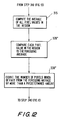
- Image processor 214 separately analyzes the pixel values in each of regions 14. Again, any of several techniques can be used for this analysis, but three exemplary techniques will be discussed here with reference to FIGS. 10-12.
- image processor 214 compares each of the pixel values associated with a region to a predetermined threshold value associated with that region (step 320). If more than a predetermined number of pixel values are below (or alternatively above) that threshold value (steps 330 and 340), the associated image region is identified as defective (step 350).
- step 380 If a predetermined number of regions (e.g., one or more) are thus found to be defective (step 380), the associated cigarette is identified as defective (step 390) and is therefore rejected when it reaches the point at which it would otherwise be transferred from drum 150 to drum 160 in the apparatus of FIG. 1.
- a predetermined number of regions e.g., one or more
- a variation of the foregoing technique is for image processor 214 to compare each pixel value in each region 14 to two predetermined threshold values associated with that region (step 320'), and to count the number of pixels having values outside the range between those thresholds (step 330'). If the resulting count is more than a predetermined number (step 340), the region is identified as having a defective image (step 350).
- FIG. 12 Another technique for analyzing the pixel values in each region 14 is shown in FIG. 12.
- FIG. 12 bears a similar relationship to FIG. 10 that FIG. 11 bears to FIG. 10, namely, the basic analytical process is shown in FIG. 10, but steps 320 and 330 in that FIG. are replaced by steps 320' and 330' in FIG. 11 or steps 315, 320", and 330" in FIG. 12.
- image processor 214 computes the average of all of the pixel values in each region (step 315). Each pixel value in the region is then compared to this average (step 320'').
- step 350 Processing then continues as described above in connection with FIG. 10.
- the technique of FIG. 12 helps render the apparatus insensitive to changes in illumination level from image to image.
- the system can be used to perform other tests on the cigarette.
- the apparatus can ensure that the length and/or diameter of the cigarette are within acceptable limits. If the cigarettes contrasts sufficiently with the supporting drum surfaces, the system can readily locate the pixel regions 14 at which the transitions between cigarette image and drum image occur. The system can then determine whether these transitions have the proper spacing side to side (cigarette diameter) or end to end (cigarette length). If not, this can form a basis for rejecting the cigarette. Other properties such as the straightness of the above-mentioned transition regions can also be tested to detect defects such as "flags" (wrapping components which are not properly or fully glued down), improperly cut ends, etc.
- image processor 214 Whenever image processor 214 detects a defective cigarette image as described above, it records that fact (e.g., in the appropriate stage of a shift register which shifts at the same rate as the cigarettes are being imaged). Thereafter, when enough inspection cycles have elapsed for the defective cigarette to travel from the imaging location (i.e., either the location opposite camera box 120a or the location opposite camera box 120b) at which it was found to be defective to the point at which it would normally transfer from drum 150 to drum 160, image processor 214 produces a reject output signal pulse which is applied to reject control 250. Reject control 250 causes inhibit transfer port 162 (FIG. 1) to emit the above-described pressurized air pulse required to prevent the defective cigarette from transferring from drum 150 to drum 160. This causes the defective cigarette to be rejected from the machine as is explained above in connection with FIG. 1.
- the system may also have a display 260 on which the images of the cigarettes and other data regarding the performance of the system are displayed.
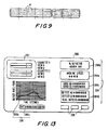
- FIG. 13 shows one possible arrangement of a video display 260.
- Four cigarette images are displayed in region 262. These may be the images most recently received by frame grabber 212.
- display 260 may hold for a few seconds any image found to be defective so that the operator of the machine can observe the defective image.
- Statistical information regarding the performance of the system is displayed in region 264. For example, in region 264a the percentage of defective cigarettes formed in this run may be displayed. In region 264b the current speed of the machine (e.g., in cigarettes per minute) may be displayed.
- region 264c the number of good images (views A and B) received from camera box 120a and the number of good images (views C and D) received from camera box 120b in this run are displayed.
- region 264d the number of defective views AB and CD, and the total number of defective views received in this run are displayed. Still other statistical information is displayed in region 266. This includes (in region 266a) a moving histogram showing the defect rate per 1000 cigarettes for the several most recent seconds of machine operation. And in region 266b a more current defect rate (e.g., the defect percentage for the most recently produced 1000 cigarettes) is displayed.
- Computational unit 216 (FIG.
- display is a so-called touch screen display
- touch screen buttons are displayed in region 268 for allowing the operator of the system to control certain aspects of the operation of the system (e.g., to reset the accumulation of statistical information or to modify the display in some desired way).
- a prism 70 may be used for this purpose as shown in FIG. 14.
- One operative portion 70a of prism 70 is used to redirect light (by refraction) from aperture 52a to camera 80, while another operative portion 70b of the prism is used to redirect light (by refraction) from aperture 52b to the camera.
- Another alternative prism embodiment 470 is shown in FIG. 15.
- light from aperture 52a enters one portion of the prism and is reflected internally off surfaces 470a and 470b in order to redirect the light toward camera 80.
- Light from aperture 52b enters another portion of prism 470 and is reflected internally off surfaces 470c and 470d in order to redirect the light toward camera 80.
- FIG. 16 shows the components of an embodiment of the second aspect of this invention.
- a rolling drum 1 that is preferably a suction drum.
- the drum has a peripheral rolling surface 2, which is caused, by a drive means (not shown), to advance at as contstant angular speed in a preferably counterclockwise direction.
- the flutes 4 extend at right angles to the direction of travel of the rolling surface 2.
- each of the flutes 4 is arranged to hold tobacco rods, double-length cigarettes or single-length cigarettes in place.
- the drum 1 is rotatable on a shaft (not shown) that extends to a conventional part of the tipper.
- the drive means for the rolling drum is also a conventional part of the tipper. In alternative embodiments, it should be understood that while certain details are considered conventional to the tipper, those details would be provided for if the embodiment of the invention being considered did not reside on the tipper.
- the first rolling block 3 is preferably a stationary block having a concave counter-surface 11 cooperating with the rolling surface 2 to define therewith an elongated curved channel or gap 8 best shown in FIG. 12.
- the gap 8 between the first rolling block 3 and the rolling drum 1 has a length sufficient to roll the tipping paper and attach the filter plug to the tobacco rods.
- the width of the gap 8 is less than the diameter of the completed cigarette so that the two surfaces cause the cigarette to roll during travel through the gap 8.
- auxiliary pieces of equipment that serve to feed the tobacco rods and filter plugs to the rolling drum and the invention.
- Such auxiliary equipment is conventional, and described, for example, in U.S. Patent No. 3,527,234 to Hinzmann.
- the depth of flutes 4 on the rolling drum 1 is only a fraction of the width of the gap 8.
- Each flute 4 is in communication with the intake ends of several radial suction ducts (not shown) and the inner or discharge ends of suction ducts. These ducts provide suction to attract the tipping paper, the tobacco rods and the filter plugs. The suction from the ducts holds the cigarettes against the force of gravity and centrifugal force while they travel along the rolling drum 1 before and after tipping and inspection.
- the completed cigarette 9 moves clear of the first rolling block 3 as it rests in its respective flute 4, held there by the suction ducts. The complete cigarette 9 is then first inspected
- a first camera 5 is provided, as shown in FIG. 16, to view the cigarette on the rolling surface 2 and is preferably two-dimensional.
- the first camera 5 has a lens arranged to receive light reflected off of the cigarette 9 as cigarette 9 travels past the first camera 5.
- a light source 20 attached to first camera 5.
- the light source 20 is arranged such that the light radiation is directed towards the portion of the rolling surface 2 focused on by the first camera 5.
- the light source 20 provides sufficient light to allow each cigarette length to reflect enough light for the camera to properly operate, thereby allowing inspection.
- the cigarette 9 remains in its respective flute 4 as the rolling drum 1 continues in a preferably counterclockwise direction.
- the cigarette 9 is rolled approximately 180° by a second rolling block 12 working in conjunction with the rolling drum 1.
- the second rolling block 12 is preferably a stationary block and has a concave counter-surface 13 cooperating with the rolling surface 2 to define therewith an elongated curved channel or gap 18.
- the gap 18 between the counter-surface 13 and the rolling surface 2 has an arc length sufficient to roll the cigarette 9 by approximately 180° from its position before entering the gap 18.
- the gap 18 has a width that is less than the diameter of the cigarette 9 so that the surfaces defining the gap cause the cigarette 9 to roll during travel through the gap.
- the concave counter-surface 13 has a surface that provides sufficient friction to rotate, but not damage, the cigarette 9.
- the counter-surface 13 has a front edge 19 to receive the cigarette 9.
- the rolling surface 2 preferably travels in a counterclockwise direction, the cigarette 9 rolls in a preferably clockwise direction in its respective flute 4.
- the rolling block 12 is described as stationary, it need only be stationary with respect to the rolling drum 1.
- the rolling block 12 is attached in an adjustable manner by an attachment means 17.
- the attachment means 17 allows the rolling block 12 to be adjusted for different cigarette diameters.
- a second camera 14 is provided, preferably two-dimensional, to inspect nearly 180° of the cigarette.
- a light source 21 attached to the second camera 14.
- the light source 21 is arranged such that the light given off is directed towards the portion of the rolling surface 2 focused on by the second camera 14.
- the light source 21 provides sufficient light to allow each cigarette to reflect enough light for the second camera 14 to properly operate, thereby allowing inspection.
- the cameras 5, 14 are video cameras that may be conventional as known to those skilled in the art.
- the first camera 5 is placed such that the lens of the camera views the cigarette after the cigarette has moved past the first rolling block.
- the second camera 14 is placed such that the lens of the camera views the cigarette after it has been rotated approximately 180° by the second rolling block 12.
- Each camera views nearly 180° of the circumference of the cigarette 9. Therefore, since the portion of the cigarette 9 hidden to the first camera 5, is inspected by the second camera 14, nearly the entire cigarette is inspected on a single rolling drum.
- the third and fourth cameras 22, 23 in addition to the individual cameras 5 and 14, there are third and fourth cameras 22, 23.
- the third camera 22 is arranged to view the cigarette at the same location on the rolling surface 2 as the first camera 5 and is also connected to the vision system 30.
- the fourth camera 23 arranged to view the cigarette at the same location on the rolling surface 2 as the second camera 14. More than one camera viewing the cigarette at each inspection point allows more than 180° of inspection of the cigarette's circumference. Thus, it is possible to inspect the entire cigarette circumference. Alternatively, any method to get two views of the completed cigarette at each of the two inspection points will allow for inspection of the entire cigarette circumference.
- a vision system 30 is employed in this invention and may be conventional.
- the vision system 30 is connected to each of the first and second cameras 5, 14 to receive the signals outputted by the camera as a result of their having viewed the cigarette 9.
- the information received from the cameras is compared to a predetermined set of characteristics.
- the vision system 30 determines such characteristics and unsatisfactory conditions as stem holes, skewed or torn tipping, spots from glue, flavors or oil, tobacco under the rod seam, torn ends on the cigarette end, and the dimensions of the cigarette (including its length and diameter).
- a vision monitoring system such as that produced by Pattern Processing Technologies, Inc., model 400 VPC TM will serve the purposes of this invention. See also U.S. Patent No. 3,049,588 to Barnett for a camera system used to inspect and compare an object to a standard.
- the cigarette 9 passes to a delivery/reject unit. As shown in FIG. 16, this comprises at least a delivery/reject drum 16.
- the delivery/reject drum 16 is a second vacuum drum with a traveling surface that rolls in a direction opposite from that of the rolling drum 1.
- the delivery/reject drum 16 receives the cigarette 9 from the rolling drum 1.
- the cigarette 9 is either rejected or, preferably, delivered by the delivery/reject drum to another part of the tipper that divides double-length cigarettes into two single-length cigarettes. Delivery of completed cigarettes by the delivery/reject drum can be to any machinery that directly follows the delivery/reject drum.
- the apparatus may be located just upstream of a cigarette packer, and then the delivery/reject drum would deliver approved completed cigarettes directly to the packer.
- a cigarette 9 is rejected if it does not meet the predetermined set of characteristics programmed into the vision system.
- Rejected completed cigarettes are sent to a recycle unit for recycling of at least the tobacco.
- Transfer of the cigarette 9 between the rolling drum 1 and the delivery/reject drum 16 may be conventional. See for example, U.S. Patent No. 3,527,234 to Hinzmann.
- the signals received from the vision system may also be conventional. See for example U.S. Patent No. 3,049,588 to Barnett.
Abstract
Description
- This invention relates to systems for optically inspecting cylindrical surfaces such as the cylindrical surfaces of cigarettes.
- It is highly desirable to be able to inspect the entire cylindrical surface of cylindrical objects such as cigarettes. Any of a wide variety of defects may occur in such objects, and it is desirable to have automated equipment for detecting those defects so that defective objects can be rejected and/or so that any malfunctioning of the machinery producing those objects can be promptly identified and corrected. In the case of cigarettes, for example, the cylindrical surface may be defective due to a piece of tobacco stem piercing the paper, an imperfection in the way the filter has been joined to the remainder of the cigarette (including the possible complete absence of the intended filter), an imperfectly formed side seal which leaves some of the tobacco visible, a discoloration of the paper, etc.
- Although inspection of this kind may take place at any stage in the production of the cigarettes, it can be advantageous to perform such inspection after processing of the individual cigarettes is complete or substantially complete. At this point in their fabrication, the individual cigarettes are most easily moved through the cigarette making machinery transverse to their length. This makes it difficult to use known cylindrical surface inspection apparatus such as that shown, for example, in Heitmann et al. U.S. patent 4,645,921, which requires the cigarettes to be passed longitudinally through the inspection apparatus.
- On the other hand, with the cigarettes moving transverse to their length it is much more difficult to image the entire surface of the cigarette. For example, the cylindrical nature of the surface makes uniform illumination of the surface and elimination of shadows difficult. Thus, it may be necessary to inspect the surface piecemeal, but it is highly desirable to keep the number of inspections to a minimum in order to avoid undue proliferation of the inspection components.
- Tobacco smoking articles, such as cigarettes and cigars, are made into rods on machines which take cut filler that is formed into a continuous rod of tobacco, and encircles the tobacco with a continuous ribbon of paper which is glued and heat-sealed. The continuous tobacco rod is formed and sealed in the making machine and then proceeds to another processing machine, such as a tipper. The tipper attaches a filter plug cut to the appropriate length between two tobacco rods. The tipper applies glue and wraps tipping paper around the filter segment and a portion of the tobacco rods. This creates a double cigarette length. The two cigarettes are then cut and oriented into a single row. A tipper as described is shown, for example, in U.S. Patent No. 3,527,234 to Hinzmann. It is the completed cigarette that is inspected for unsatisfactory conditions.
- Optical scanning of cigarettes during production is taught by U.S. Patent No. 4,277,678 to Wahle et al. There, a cigarette is inspected in the tipping machine by two optoelectrical units mounted on a single rolling drum. The cigarette is stopped in its path and rotated using a separate rotary element while the optoelectrical units scan the cigarette's wrapper for unsatisfactory conditions. Each optoelectrical unit scans the entire cigarette for particular unsatisfactory conditions.
- Other cigarette inspection systems test the cigarettes at several testing stations. Each station tests the cigarette for one or two different types of unsatisfactory conditions. U.S. Patent No. 4,403,620 to Joseph et al., U.S. Patent No. 4,484,591 to Wahle et al. and U.S. Patent No. 4,901,860 to Wahle et al. all teach separate testing stations for different unsatisfactory conditions in cigarettes.
- Still other cigarette inspection systems use more than one drum to create more than one inspection zone. U.S. Patent No. 4,639,592 to Heitman passes cigarettes before optical inspection devices located at certain points along a predetermined path. The path requires at least two vacuum drums each to expose one side of the cigarette. Note that Heitman specifically prefers to not mechanically rotate the cigarette. Great British Patent No. 2,221,029 teaches a similar method.
- Further, other devices inspect cigarettes before they are completed. For example, U.S. Patent No. 4,350,170 to Baier teaches inspection of the cigarette rod as it comes off the rod making machine by passing the rod through an annular housing. A similar device is taught by U.S. Patent No. 4,208,578 to McLoughlin et al.
- None of the devices known currently in the field, inspect cigarettes in the simple, effective, compact system as disclosed herein. This invention provides a method and apparatus to inspect cigarettes at the speeds of modern production while inspecting nearly the entire cigarette.
- It should also be noted that any successful inspection system for products such as cigarettes must be extremely fast in order to keep pace with the high speeds at which such products are typically made. For example, it is now common for a single cigarette making machine to make cigarettes at rates approaching 10,000 per minute. A successful cigarette inspection system must also be able to inspect for relatively small and/or subtle defects (e.g., a hole as small as about .5 millimeter in diameter or a minor discoloration of the cigarette paper).
- In view of the foregoing, it has been desired to improve and simplify systems for inspecting cylindrical surfaces.
- It has also been desired to provide cylindrical surface inspection systems which are capable of inspecting the entire circumference of such surfaces at very high speeds.
- It has also been desired to provide an apparatus and method to visually inspect completed cigarettes.
- It has also been desired to provide an apparatus and method to that will automatically reject assembled cigarettes that do not meet inspection standards.
- It has also been desired to provide an apparatus and method to visually inspect nearly 360° of the circumference of the assembled cigarette.
- It has also been desired to provide an apparatus and method to visually inspect nearly the entire surface of an assembled cigarette in a compact, efficient space employing a minimum of equipment.
- According to the invention there is provided apparatus for optically inspecting substantially the entire cylindrical surface of a cylindrical object comprising:
a first support for supporting the object so that a first side of the said surface of the object is exposed;
a first image former for forming a first image of the said first side;
means for exposing a second side of the said surface of the object, the first and second sides together including the whole of the said surface;
a second image former for forming a second image of the said second side, the first and second sides together including the entire cylindrical surface of the object. - There is also provided, according to the invention a method for optically inspecting substantially the entire cylindrical surface of a cylindrical object comprising:
supporting the object on a support surface;
inspecting a first portion of the cylindrical surface of the object to generate an image;
rotating the object through 180°;
inspecting a second portion of the cylindrical surface of the object, the first and second portions together including the entire cylindrical surface of the object to generate another image;
analyzing each image to determine whether or not they meet a predetermined criterion; and
rejecting the object if the predetermined criterion is not met. - In a first aspect, the invention provides cylindrical surface inspection systems in which the object having the cylindrical surface is first supported (e.g., on the surface of a first rotating drum) so that one side of the object (preferably including at least half of the circumference of the cylinder) is exposed for optical inspection along a substantial length of the object. The exposed portion of the surface is illuminated by light from two linear light sources. These two light sources are aligned with the longitudinal axis of the cylindrical surface and are spaced apart by a relatively large distance circumferentially of the cylindrical surface so that collectively they preferably illuminate at least half of the circumference of the surface. Light reflected from the surface in two radially different directions is then used to form images of the surface. The two reflected light directions are preferably intermediate the directions from which the light arrives from the two light sources. However, the two reflected light directions are preferably sufficiently widely spaced circumferentially of the cylindrical surface so that collectively they provide image information regarding at least half the circumference of the surface. Optical components are preferably provided to direct the light reflected from the above-mentioned two directions to a single camera to reduce the number of cameras required.
- After passing the point at which the first side of the object is imaged as described above, the support for the object is changed to expose the other side for optical inspection. For example, the object may be transferred from the surface of the above-mentioned first rotating drum to the surface of a second rotating drum. Again, preferably at least half the circumference of the cylinder is exposed. This newly exposed portion of the surface is illuminated and imaged in the same way that the first side is illuminated and imaged. A second camera (aided by optical components similar to those mentioned above in connection with the first camera) receives the reflected light from the two directions associated with the second side of the object.
- Because the images of the cylindrical surface of the object typically do not fill the entire field of view of either of the above-mentioned cameras, only the portions of the camera screens containing cylindrical surface image information are scanned. The resulting saving in scanning time greatly speeds the operation of the system.
- Each partial image of the cylindrical surface is analyzed to detect any defects in appearance. Although any of a wide variety of image analysis techniques can be used, in the preferred embodiments, each image is subdivided into a plurality of regions, each of which is aligned with the longitudinal axis of the cylindrical surface, and each of which is only a relatively small fraction of the dimension of the image transverse to that longitudinal axis. The image information in each of these regions is compared to expected information for that region (e.g., on an absolute or relative basis). Aligning the regions with the longitudinal axis of the cylindrical surface and confining each region to a small fraction of the circumference of the cylinder increases the sensitivity of the system to possible variations in the illumination level of the object in the circumferential direction.
- On the basis of the foregoing analysis, any object having any unacceptable image is identified and preferably rejected so that it does not continue on for the further processing to which acceptable objects are subjected.
- This system also preferably includes means for displaying the images of the objects, especially the images of defective objects, so the operator of the system can observe the nature of any defects. The system may also display information regarding such statistics as the number and/or percentage of defective objects encountered.
- The invention provides in a second aspect a machine vision system comprising at least two-dimensional video cameras to inspect cigarettes at two positions on a single rolling drum, preferably as part of the tipper. There is at least one rolling block that works in conjunction with the rolling drum to roll the cigarette.
- In the preferred operation, the first rolling block attaches a filter plug to the tobacco rods, as part of the standard tipping operation of the tipper. Located after the first rolling block is a first two-dimensional video camera to inspect nearly the entire first half of the completed single- or double-length cigarette. A second rolling block is then provided to roll the cigarette approximately 180°. Located after the second rolling block is a second two-dimensional video camera to inspect nearly the entire second half of the cigarette.
- In an alternative embodiment, a rolling drum can be provided after the tipper to provide the space needed for a first inspection, rolling the completed cigarette and then a second inspection. This drum could also be located just at the end of the tipper.
- The vision system determines, from the information provided by the video cameras, whether the cigarette meets the preset characteristics for a completed cigarette. If the cigarette does not meet those characteristics, the cigarette is removed from the cigarette manufacturing system by a delivery/reject drum. The delivery/reject drum is located directly after the rolling drum and may be conventional.
- The second aspect of the invention provides a compact, efficient system for inspecting completed cigarettes at the high speeds of production encountered in today's modern manufacturing systems.
- The invention will be further described, by way of example, with reference to the drawings, in which:
- FIG. 1 is a simplified elevational view of illustrative cylindrical surface inspection apparatus constructed in accordance with the first aspect of the invention;
- FIG. 2 is a more detailed view of a representative portion of the apparatus of FIG. 1;
- FIG. 3 is a view taken along the line 3-3 in FIG. 2;
- FIG. 4 is a simplified elevational view of a component which can be used in place of the component shown in FIG. 3;
- FIG. 5 is a simplified view taken generally along the line 5-5 in FIG. 2;
- FIG. 6 is a block diagram of illustrative control and analysis apparatus constructed in accordance with the principles of the first aspect of the invention;
- FIGS. 7a and 7b are illustrative images formed on the video cameras in the apparatus of FIG. 1;
- FIG. 8 shows a composite of the images of FIGS. 7a and 7b which is formed in the apparatus of FIG. 6;
- FIG. 9 is a diagram which is useful in explaining how the apparatus of FIG. 6 may analyze images;
- FIGS. 10a and 10b (collectively referred to as FIG. 10) are a flow chart of an illustrative image analysis process which can be carried out in the apparatus of FIG. 6;
- FIG. 11 is a flow chart showing how two steps in FIG. 10 can be modified to analyze images somewhat differently ;
- FIG. 12 is a flow chart showing another possible modification of the above-mentioned two steps in FIG. 10;
- FIG. 13 is a simplified rendering of a typical display on the display component in the apparatus of FIG. 6;
- FIG. 14 shows an alternative embodiment of a portion of FIG. 2;
- FIG. 15 shows another alternative embodiment of a portion of FIG. 2;
- FIG. 16 is a view of an embodiment of apparatus according to the second aspect of the invention isolated from the other parts of the tipper;
- FIG. 17 is a detailed view of the first rolling block working of FIG 1 in conjunction with the rolling drum; and
- FIG. 18 is a detailed view of the second rolling block of FIG. 1 working in conjunction with the rolling drum.
- Although the principles of this invention are equally applicable to inspecting the cylindrical surfaces of other types of objects, the invention will be fully understood from the following explanation of its application to inspecting the cylindrical surfaces of finished or substantially finished cigarettes.
- FIG. 1 shows the
final portion 100 of a conventional Max S cigarette tipping machine which has been modified to include apparatus according to the first aspect of the present Max S machine is manufactured by Hauni-Werke Korber & Co. KG. of Hamburg, Germany. By thetime cigarettes 12 reach the portion of the machinery shown in FIG. 1, the fabrication of the cigarettes is complete and it remains only to inspect them. Accordingly, as is conventional, the finished cigarettes are deposited one after another on conventionalrotating inspection drum 110.Inspection drum 110 has a plurality of circumferentially spaced, axially extendingflutes 112 on its outer surface. Each flute receives onecigarette 12, and the cigarette is held in the flute by reduced pressure ("vacuum") which is communicated to the bottom of the flute by passageways extending radially to the flute from a vacuum plenum in the interior of the drum. Such vacuum is typically applied only throughout the portion of the circumference of the drum to which the cigarettes are to be held as the drum rotates to convey the cigarettes. When a flute reaches the angular location at which the cigarette in that flute is to be transferred to another drum, the vacuum to that flute is cut off so that the next drum can pick up the cigarette with no resistance from the first drum. It will be noted thatflutes 112 are shallow enough so that more than half the circumference of each cigarette is exposed. - While the cigarettes are on
inspection drum 110 they are inspected in the conventional way by inspection apparatus (not shown) which is part of the Hauni machinery. For example, a typical conventional inspection test is a "dilution check" to make sure that the cigarette has the proper resistance to longitudinal air flow. - In addition, while the cigarettes are on
drum 110, they also pass dualimage camera box 120a which is part of the optical inspection system of this invention. As will be described in more detail below,camera box 120a illuminates more than 180° of the circumference of the cylindrical surface of each cigarette passing in front of it and forms two angularly spaced images of that surface. These two images collectively cover more than 180° of the circumference of the cylindrical surface of the cigarette. It should be noted thatcamera box 120a is preferably located adjacent an upper portion of the circumference ofinspection drum 110, and that it is also preferably angled down toward the cigarette which is being illuminated and imaged. This helps keep any dust and debris from accumulating on the front ofbox 120a (i.e., the side directed toward the cigarettes). Such dust and debris could interfere with proper illumination and imaging of the cigarettes in accordance with this invention. - After passing
camera box 120a, the cigarettes are transferred frominspection drum 110 toconventional reject drum 130.Drum 130 is a rotating, fluted, vacuum drum likedrum 110. Any cigarette which the conventional Hauni inspection apparatus has found to be defective ondrum 110 is blown offreject drum 130 and thereby rejected in the conventional way by conventional Hauni reject apparatus (not shown). Cigarettes found to be defective by the optical inspection apparatus of the first aspect of the invention are rejected at a later point as is explained below. - After passing approximately half way around reject
drum 130, the cigarettes are transferred to conventional transfer drum 140. Transfer drum 140 is another rotating, fluted, vacuum drum like the previously described drums. Drum 140 conveyscigarettes 12 fromreject drum 130 toelevator drum 150. -
Elevator drum 150 is still another substantially conventional, rotating, fluted, vacuum drum like those described above, although certain modifications ofdrum 150 in accordance with the first aspect of the invention are discussed below.Elevator drum 150 conveyscigarettes 12 from transfer drum 140 past a second dual image camera box 120b to stackerdrum 160. Camera box 120b may be substantially identical tobox 120a. Accordingly, box 120b illuminates more than 180° of the exposed cylindrical surface of each cigarette passing box 120b ondrum 150, and also forms two angularly spaced images of that surface. Again, these two images cover more than half the circumference of the cigarette surface. It will be noted, however, that the side of each cigarette exposed ondrum 150 is diametrically opposite the side which is exposed ondrum 110. Accordingly, the four images formed bycamera boxes 120a and 120b collectively cover the entire circumference of the cylindrical surface of each cigarette. Indeed, each of these four images preferably overlaps the two circumferentially adjacent images to some extent to ensure that no part of the circumference of any cigarette is uninspected. It will also be noted that camera box 120b is adjacent an upper portion ofdrum 150, and that box 120b is angled down toward the cigarette that is being illuminated and imaged by that box. As in the case ofcamera box 120a, this helps keep dust and debris from accumulating on the front of box 120b and interfering with the performance of the box. Associatingcamera boxes 120a and 120b with two widely spaceddrums 110 and 150 (i.e., drums which are spaced apart by twoother drums 130 and 140) facilitates positioning both of the camera boxes so that they are adjacent the upper portion of a drum and directed downwardly so that neither accumulates dust and debris. - By the time each cigarette is approaching the top of
elevator drum 150, the optical inspection apparatus of the first aspect of the invention has completed its inspection and analysis of the cigarette and has made a determination as to whether or not the cigarette has an acceptable appearance. If the appearance of the cigarette is acceptable, the cigarette is transferred fromelevator drum 150 tostacker drum 160. On the other hand, if the appearance of the cigarette is not acceptable, transfer of the cigarette fromdrum 150 to drum 160 is prevented by a brief blast of pressurized air from inhibit transfer port 162 (see US patent application Serial No. 884 741. Accordingly, the defective cigarette remains ondrum 150.Drum 150 is modified so that the vacuum, which is turned off adjacent the nip betweendrums drum 150 tostripper 152 which strips the defective cigarettes from the drum in order to reject them. The cigarettes extend axially beyond both end faces ofdrum 150 so that fingers ofstripper 152 adjacent those end faces can engage the cigarettes and strip them from the drum. The rejected cigarettes collected bystripper 152 are conveyed out of the machine (e.g., by pressurized air flowing through the stripper). - Returning to the discussion of
drum 160, cigarettes which have not been rejected by either the conventional Hauni reject mechanisms associated withreject drum 130 or the above-described reject mechanism of this invention transfer to drum 160 and are conveyed by that drum to the conventionalstack forming region 170 of the machine. Stack former 170 removes the cigarettes fromdrum 160 and forms them into a stack for conveyance bymass flow conveyor 180. Alternatively, a conventional tray filler may be used to fill trays with the cigarettes removed fromdrum 160. - Turning now to a more detailed consideration of the construction and operation of dual
image camera boxes 120a and 120b, the major components of a typical one of such boxes are shown in FIG. 2.Box 120 in FIG. 2 may be eitherbox 120a or box 120b in FIG. 1. Similarly, drum 20 in FIG. 2 may be either drum 110 ordrum 150 in FIG. 1. Although shown rotating counterclockwise in FIG. 2, drum 20 may rotate in either direction in front ofbox 120. - As
drum 20 revolves, it positionscigarettes 12 one after another midway between twolinear light sources 30a and 30b associated withcamera box 120. In FIG. 2 the cigarette identified by the letter A is thus positioned midway between the light sources. The linear axis of each oflight sources 30 is substantially parallel to the longitudinal axis of cigarette A (i.e., perpendicular to the plane in which FIG. 2 is drawn). Althoughlight sources 30 may illuminate any substantial portion of the length of cigarette A (e.g., at least a length greater than the circumference of the cigarette), in the depicted preferred embodimentlight sources 30 illuminate the entire length of the cigarette. Both oflight sources 30 are aimed at the cylindrical surface of cigarette A. However,light sources 30 are spaced apart quite widely in the circumferential direction around cigarette A. Accordingly,light sources 30 collectively illuminate the entire exposed surface of cigarette A. For example, in the particular embodiment shown in FIG. 2 the angle betweenlight sources 30 is approximately 118° so that approximately 270° of the circumference of cigarette A is illuminated by the combined effect of the two light sources. The illumination of cigarette A fromlight sources 30 is preferably both axially and circumferentially quite uniform and free from shadows (e.g., from cigarette A itself and from other cigarettes which are circumferentially adjacent to cigarette A on drum 20). -
Light sources 30 may be provided in any of several ways. In the embodiment shown in FIGS. 2 and 3, for example, optical fibers are used. The ends 33 ofseveral bundles 32 of optical fibers are fanned or combed out in a linear array behind a translucent plastic (e.g., Lexan)strip 34. This array of optical fibers is stabilized and aimed at cigarette A by being clamped betweenmembers Strip 34 somewhat diffuses the light from the optical fibers to help promote uniform illumination of cigarette A. As an alternative (shown in FIG. 4), eachlight source 30 could be formed of a line oflight emitting diodes 40. - Although the illumination produced by
light sources 30 is described above as axially uniform, the light produced by these light sources can be "programmed" in various ways if desired. For example, to compensate for a possible difference in the distance betweenlight sources 30 and cigarette A, the farther light source could be illuminated more brightly. Similarly, to enhance or deemphasize certain features or regions of cigarette A, corresponding axial portions oflight sources 30 could be illuminated more or less brightly than other axial portions. Not all of eachlight source 30 may need to be illuminated at the same time, but instead the illumination could "scan" along the length of the light source. The "color" oflight sources 30 can also be selected as desired. For example, it may be desired to use infrared (IR) light sources combined with IR filtering of the light reflected from cigarette A in order to reduce or eliminate disturbances from ambient light. - Regardless of the structure of
light sources 30, they are preferably strobed (i.e., briefly illuminated) each time a cigarette is properly positioned between them ondrum 20. This has the effect of "freezing" the motion of the cigarette being inspected. - Light reflected from two circumferentially different (although preferably immediately adjacent or even somewhat overlapping) regions of cigarette A illuminated by
light sources 30 passes throughapertures aperture plate 50 which is located betweenlight sources 30 opposite cigarette A. Likelight sources 30, apertures 52 are preferably linear and parallel to the longitudinal axis of cigarette A (see also FIG. 5). Although apertures 52 could be shorter (e.g., in the event thatlight sources 30 illuminate only a portion of the length of cigarette A), in the depicted preferred embodiment in whichlight sources 30 illuminate the full length of cigarette A, apertures 52 are also long enough to pass light reflected from the entire length of the cigarette. The thickness ofaperture plate 50 and the sizes and shapes of apertures 52 are preferably chosen to mask light reflected from extraneous surfaces such as the surfaces of the cigarettes adjacent to cigarette A ondrum 20. In addition, the masking effect of apertures 52 is preferably enhanced by anotheraperture plate 54 behindplate 50 with apertures 56 that are optically aligned with apertures 52 to thereby effectively increase the thickness ofplate 50. Although betweenlight sources 30 and therefore closer together than the light sources, apertures 52 are nevertheless spaced sufficiently far apart circumferentially of cigarette A so that collectively they pass light reflected from at least half (and preferably somewhat more than half) the circumference of that cigarette. For example, in the particular embodiment shown in FIG. 2 the angle between the optical paths defined by apertures 52 is approximately 57° so that approximately 240° of the circumference of cigarette A is imaged by the combined effect of these two apertures. - The reflected light passing through
aperture 52a is directed to one portion of the photosensitive image surface ofconventional video camera 80 bymirrors aperture 52b is directed to another portion of the image area ofcamera 80 bymirrors camera 80 receives image information for at least half (preferably more than half) the circumference of the surface of cigarette A and produces a video output signal indicative of all of that image information. - In order to ensure that both of the images received by
camera 80 are focused, the length of the paths along which both images travel must be the same.Mirrors - Although various types of video cameras can be employed, in the preferred embodiments in which images must be captured at very high speeds (e.g., at the rate of approximately 10,000 per minute),
camera 80 is preferably a high speed, charge coupled device ("CCD") camera. - FIG. 6 shows an illustrative embodiment of control and
analysis apparatus 200 for the optical inspection systems of the first aspect of the invtion. Much ofapparatus 200 is commercially available optical inspection apparatus (e.g., the 400 VPC machine vision system available from Pattern Processing Technologies, Inc. of Eden Prairie, Minnesota, although this apparatus has been specially adapted and programmed as discussed below in accordance with the present invention. A central component ofapparatus 200 isprocessor 210.Processor 210 includes three major subsystems. These areframe grabber 212,image processor 214, and computational unit 216 (e.g., a conventional microprocessor). -
Shaft encoder 220 is associated with the mechanical portion of the cigarette making machine (e.g., the apparatus shown in FIG. 1) and produces an output signal pulse after each predetermined increment of motion of the machinery. For example,shaft encoder 220 may be thought of as producing an output pulse each time a cigarette is positioned at location A (FIG. 2) opposite either ofcamera boxes 120. (Although not mentioned previously, it will be understood thatcamera boxes 120 are preferably positioned in FIG. 1 so that both boxes have a cigarette at the associated location A at the same time.) -
Image processor 214 receives the above-mentioned shaft encoder pulses and causes the remainder ofapparatus 200 to perform one complete cycle of operation in response to each pulse. In particular, in response to receipt of a shaft encoder pulse indicating that a cigarette is at position A opposite each ofcamera boxes 120,image processor 214 causesstrobe circuitry 230 to briefly illuminate thelight sources 30 of bothcamera boxes 120.Image processor 214 also causesframe grabber 212 to begin the scanning of thecameras 80 in both camera boxes. - As suggested above, the cigarette images captured by one of boxes 120 (e.g.,
box 120a) are preferably directed to the portion of the photosensitive area of thecamera 80 in that box which is first to be scanned, while the cigarette images captured by the other of boxes 120 (e.g., box 120b) are preferably directed to the portion of the photosensitive area of thecamera 80 in the second box which is scanned immediately after the above-mentioned portion of the first camera has been scanned. This is illustrated by FIGS. 7a and 7b, which respectively show how the cigarette images fall on the photosensitive areas of the cameras inboxes 120a and 120b in the above-described example. -
Frame grabber 212 initially controlsmultiplexer 240 to pass only the output signal of the camera inbox 120a (assuming that the camera in that box receives the image shown in FIG. 7a). After the meaningful portion of the image captured bybox 120a has been scanned,frame grabber 212 causes multiplexer 240 to switch so that it passes only the output signal of the camera in box 120b. Accordingly, the output signal ofmultiplexer 240 represents a composite of the FIGS. 7a and 7b images as shown in FIG. 8.Frame grabber 212 stops all scanning of the cameras inboxes 120 after all meaningful image information has been scanned. For example, in a preferred embodiment in which the photosensitive area of each camera is 640 pixels wide (parallel to the longitudinal axes of the cigarette images) by 480 pixels high, it may only be necessary to scan about 200 to 230 lines of the photosensitive areas of the cameras. The first 100 to 115 scan lines in the output signal ofmultiplexer 240 then come from the camera inbox 120a, while the remaining 100 to 115 lines come from the camera in box 120b. The placement of the meaningful image information on the photosensitive areas of the cameras so that only portions of those areas need to be scanned, and the resulting partial scanning of the photosensitive areas, greatly increases the speed with which the system can process images. - In addition to controlling the scanning operations of the cameras in
boxes 120,frame grabber 212 digitizes the analog video output signal of multiplexer 240 (e.g., by associating an appropriate one of 256 digital gray scale values with each pixel). The resulting digital image data is passed to imageprocessor 214 for analysis to determine if the cigarette images contain any defects. - Although
image processor 214 could analyze the cigarette images in other ways, in the depicted preferredembodiment image processor 214 subdivides each cigarette image into manysmall regions 14 as shown, for example, in FIG. 9. Eachregion 14 is a rectangle having a relatively long dimension aligned with the longitudinal axis of the cigarette and a short dimension which is only a fraction of the width of the cigarette image (transverse to the longitudinal axis of cigarette). For example, each region may be 40 pixels long (parallel to the longitudinal axis of the cigarette) by two pixels wide. Use of such fairly small regions facilitates detection of relatively small image defects. Use of regions which are only a small fraction of the width of the cigarette images (perpendicular to the longitudinal axis of the cigarette) helps the system compensate or adjust for possible nonuniformity in the level of illumination of the cigarette in the circumferential direction. This latter point will become more apparent as the discussion proceeds. -
Image processor 214 separately analyzes the pixel values in each ofregions 14. Again, any of several techniques can be used for this analysis, but three exemplary techniques will be discussed here with reference to FIGS. 10-12. In the first technique (FIG. 10), after performingstep 310 to subdivide the image intoregions 14 as described above,image processor 214 compares each of the pixel values associated with a region to a predetermined threshold value associated with that region (step 320). If more than a predetermined number of pixel values are below (or alternatively above) that threshold value (steps 330 and 340), the associated image region is identified as defective (step 350). If a predetermined number of regions (e.g., one or more) are thus found to be defective (step 380), the associated cigarette is identified as defective (step 390) and is therefore rejected when it reaches the point at which it would otherwise be transferred fromdrum 150 to drum 160 in the apparatus of FIG. 1. - A variation of the foregoing technique (shown in FIG. 11) is for
image processor 214 to compare each pixel value in eachregion 14 to two predetermined threshold values associated with that region (step 320'), and to count the number of pixels having values outside the range between those thresholds (step 330'). If the resulting count is more than a predetermined number (step 340), the region is identified as having a defective image (step 350). - Another technique for analyzing the pixel values in each
region 14 is shown in FIG. 12. (FIG. 12 bears a similar relationship to FIG. 10 that FIG. 11 bears to FIG. 10, namely, the basic analytical process is shown in FIG. 10, but steps 320 and 330 in that FIG. are replaced by steps 320' and 330' in FIG. 11 orsteps image processor 214 computes the average of all of the pixel values in each region (step 315). Each pixel value in the region is then compared to this average (step 320''). If more than a predetermined number of pixels have values which deviate from this average by more than a predetermined amount (steps 330" and 340), the region is identified as having a defective image (step 350). Processing then continues as described above in connection with FIG. 10. The technique of FIG. 12 helps render the apparatus insensitive to changes in illumination level from image to image. - In addition to performing overall inspection of the cigarette images for defects in appearance, the system can be used to perform other tests on the cigarette. For example, the apparatus can ensure that the length and/or diameter of the cigarette are within acceptable limits. If the cigarettes contrasts sufficiently with the supporting drum surfaces, the system can readily locate the
pixel regions 14 at which the transitions between cigarette image and drum image occur. The system can then determine whether these transitions have the proper spacing side to side (cigarette diameter) or end to end (cigarette length). If not, this can form a basis for rejecting the cigarette. Other properties such as the straightness of the above-mentioned transition regions can also be tested to detect defects such as "flags" (wrapping components which are not properly or fully glued down), improperly cut ends, etc. - Whenever
image processor 214 detects a defective cigarette image as described above, it records that fact (e.g., in the appropriate stage of a shift register which shifts at the same rate as the cigarettes are being imaged). Thereafter, when enough inspection cycles have elapsed for the defective cigarette to travel from the imaging location (i.e., either the location oppositecamera box 120a or the location opposite camera box 120b) at which it was found to be defective to the point at which it would normally transfer fromdrum 150 to drum 160,image processor 214 produces a reject output signal pulse which is applied to rejectcontrol 250.Reject control 250 causes inhibit transfer port 162 (FIG. 1) to emit the above-described pressurized air pulse required to prevent the defective cigarette from transferring fromdrum 150 to drum 160. This causes the defective cigarette to be rejected from the machine as is explained above in connection with FIG. 1. - In addition to inspecting and rejecting defective cigarettes, the system may also have a
display 260 on which the images of the cigarettes and other data regarding the performance of the system are displayed. For example, FIG. 13 shows one possible arrangement of avideo display 260. Four cigarette images are displayed inregion 262. These may be the images most recently received byframe grabber 212. If desired,display 260 may hold for a few seconds any image found to be defective so that the operator of the machine can observe the defective image. Statistical information regarding the performance of the system is displayed inregion 264. For example, in region 264a the percentage of defective cigarettes formed in this run may be displayed. Inregion 264b the current speed of the machine (e.g., in cigarettes per minute) may be displayed. Inregion 264c the number of good images (views A and B) received fromcamera box 120a and the number of good images (views C and D) received from camera box 120b in this run are displayed. Inregion 264d the number of defective views AB and CD, and the total number of defective views received in this run are displayed. Still other statistical information is displayed inregion 266. This includes (in region 266a) a moving histogram showing the defect rate per 1000 cigarettes for the several most recent seconds of machine operation. And in region 266b a more current defect rate (e.g., the defect percentage for the most recently produced 1000 cigarettes) is displayed. Computational unit 216 (FIG. 6) may compute and provide the displayed statistical information (e.g., by counting frame initiation and reject initiation output pulses from image processor 214). Lastly, assuming that display is a so-called touch screen display, several touch screen "buttons" are displayed inregion 268 for allowing the operator of the system to control certain aspects of the operation of the system (e.g., to reset the accumulation of statistical information or to modify the display in some desired way). - It will be understood that the foregoing is merely illustrative of the principles of the first aspect of the invention, and that various modifications can be made by those skilled in the art.
- For example, as an alternative to the system of
mirrors camera 80, aprism 70 may be used for this purpose as shown in FIG. 14. One operative portion 70a ofprism 70 is used to redirect light (by refraction) fromaperture 52a tocamera 80, while another operative portion 70b of the prism is used to redirect light (by refraction) fromaperture 52b to the camera. Anotheralternative prism embodiment 470 is shown in FIG. 15. In this alternative, light fromaperture 52a enters one portion of the prism and is reflected internally offsurfaces 470a and 470b in order to redirect the light towardcamera 80. Light fromaperture 52b enters another portion ofprism 470 and is reflected internally offsurfaces 470c and 470d in order to redirect the light towardcamera 80. - FIG. 16 shows the components of an embodiment of the second aspect of this invention. There is a rolling
drum 1 that is preferably a suction drum. The drum has a peripheral rollingsurface 2, which is caused, by a drive means (not shown), to advance at as contstant angular speed in a preferably counterclockwise direction. On the rollingsurface 2, there are a plurality of successive axiallyparallel flutes 4 spaced from each other by identical distances. Theflutes 4 extend at right angles to the direction of travel of the rollingsurface 2. Also, each of theflutes 4 is arranged to hold tobacco rods, double-length cigarettes or single-length cigarettes in place. Thedrum 1 is rotatable on a shaft (not shown) that extends to a conventional part of the tipper. The drive means for the rolling drum is also a conventional part of the tipper. In alternative embodiments, it should be understood that while certain details are considered conventional to the tipper, those details would be provided for if the embodiment of the invention being considered did not reside on the tipper. - It should also be understood that although double-length cigarettes are referred to throughout this portion of the description to describe a preferred embodiment of this invention, one of ordinary skill in the art will appreciate that single-length cigarettes could also be inspected using this invention. As such, the term "completed cigarette" will be used to mean any cigarette whether single or double-length, and whether attached to a filter or not.
- Working in conjunction with the rolling
drum 1 is a first rolling block 3. The first rolling block 3 is preferably a stationary block having aconcave counter-surface 11 cooperating with the rollingsurface 2 to define therewith an elongated curved channel or gap 8 best shown in FIG. 12. The gap 8 between the first rolling block 3 and the rollingdrum 1 has a length sufficient to roll the tipping paper and attach the filter plug to the tobacco rods. The width of the gap 8 is less than the diameter of the completed cigarette so that the two surfaces cause the cigarette to roll during travel through the gap 8. There are several auxiliary pieces of equipment that serve to feed the tobacco rods and filter plugs to the rolling drum and the invention. There is also auxiliary equipment to remove the completed cigarettes from the rolling drum. Such auxiliary equipment is conventional, and described, for example, in U.S. Patent No. 3,527,234 to Hinzmann. - The depth of
flutes 4 on the rollingdrum 1 is only a fraction of the width of the gap 8. Eachflute 4 is in communication with the intake ends of several radial suction ducts (not shown) and the inner or discharge ends of suction ducts. These ducts provide suction to attract the tipping paper, the tobacco rods and the filter plugs. The suction from the ducts holds the cigarettes against the force of gravity and centrifugal force while they travel along the rollingdrum 1 before and after tipping and inspection. - After the filter plug has been attached to the tobacco rods, the completed
cigarette 9 moves clear of the first rolling block 3 as it rests in itsrespective flute 4, held there by the suction ducts. Thecomplete cigarette 9 is then first inspected - It will be appreciated by one of skill in the art that should the rolling drum be located at the end of or after the tipper, then the first inspection will be after the completed cigarette is transferred to the rolling drum. A
first camera 5 is provided, as shown in FIG. 16, to view the cigarette on the rollingsurface 2 and is preferably two-dimensional. Thefirst camera 5 has a lens arranged to receive light reflected off of thecigarette 9 ascigarette 9 travels past thefirst camera 5. - In a preferred embodiment, there is a
light source 20 attached tofirst camera 5. Thelight source 20 is arranged such that the light radiation is directed towards the portion of the rollingsurface 2 focused on by thefirst camera 5. Thelight source 20 provides sufficient light to allow each cigarette length to reflect enough light for the camera to properly operate, thereby allowing inspection. - The
cigarette 9 remains in itsrespective flute 4 as the rollingdrum 1 continues in a preferably counterclockwise direction. After inspection by thefirst camera 5, thecigarette 9 is rolled approximately 180° by asecond rolling block 12 working in conjunction with the rollingdrum 1. As shown in FIG. 18, thesecond rolling block 12 is preferably a stationary block and has aconcave counter-surface 13 cooperating with the rollingsurface 2 to define therewith an elongated curved channel orgap 18. Thegap 18 between the counter-surface 13 and the rollingsurface 2 has an arc length sufficient to roll thecigarette 9 by approximately 180° from its position before entering thegap 18. Thegap 18 has a width that is less than the diameter of thecigarette 9 so that the surfaces defining the gap cause thecigarette 9 to roll during travel through the gap. Theconcave counter-surface 13 has a surface that provides sufficient friction to rotate, but not damage, thecigarette 9. The counter-surface 13 has afront edge 19 to receive thecigarette 9. As the rollingsurface 2 preferably travels in a counterclockwise direction, thecigarette 9 rolls in a preferably clockwise direction in itsrespective flute 4. While the rollingblock 12 is described as stationary, it need only be stationary with respect to the rollingdrum 1. In a preferred embodiment, the rollingblock 12 is attached in an adjustable manner by an attachment means 17. The attachment means 17 allows the rollingblock 12 to be adjusted for different cigarette diameters. - After the
cigarette 9 has been rotated, asecond camera 14 is provided, preferably two-dimensional, to inspect nearly 180° of the cigarette. In a preferred embodiment, there is alight source 21 attached to thesecond camera 14. Thelight source 21 is arranged such that the light given off is directed towards the portion of the rollingsurface 2 focused on by thesecond camera 14. Thelight source 21 provides sufficient light to allow each cigarette to reflect enough light for thesecond camera 14 to properly operate, thereby allowing inspection. - The
cameras first camera 5 is placed such that the lens of the camera views the cigarette after the cigarette has moved past the first rolling block. Thesecond camera 14 is placed such that the lens of the camera views the cigarette after it has been rotated approximately 180° by thesecond rolling block 12. Each camera views nearly 180° of the circumference of thecigarette 9. Therefore, since the portion of thecigarette 9 hidden to thefirst camera 5, is inspected by thesecond camera 14, nearly the entire cigarette is inspected on a single rolling drum. - In a preferred embodiment, in addition to the
individual cameras fourth cameras third camera 22 is arranged to view the cigarette at the same location on the rollingsurface 2 as thefirst camera 5 and is also connected to thevision system 30. Thefourth camera 23 arranged to view the cigarette at the same location on the rollingsurface 2 as thesecond camera 14. More than one camera viewing the cigarette at each inspection point allows more than 180° of inspection of the cigarette's circumference. Thus, it is possible to inspect the entire cigarette circumference. Alternatively, any method to get two views of the completed cigarette at each of the two inspection points will allow for inspection of the entire cigarette circumference. - A
vision system 30 is employed in this invention and may be conventional. Thevision system 30 is connected to each of the first andsecond cameras cigarette 9. Generally, the information received from the cameras is compared to a predetermined set of characteristics. Thevision system 30 determines such characteristics and unsatisfactory conditions as stem holes, skewed or torn tipping, spots from glue, flavors or oil, tobacco under the rod seam, torn ends on the cigarette end, and the dimensions of the cigarette (including its length and diameter). For example, a vision monitoring system such as that produced by Pattern Processing Technologies, Inc.,model 400 VPCTM will serve the purposes of this invention. See also U.S. Patent No. 3,049,588 to Barnett for a camera system used to inspect and compare an object to a standard. - After the second camera inspection, the
cigarette 9 passes to a delivery/reject unit. As shown in FIG. 16, this comprises at least a delivery/reject drum 16. The delivery/reject drum 16 is a second vacuum drum with a traveling surface that rolls in a direction opposite from that of the rollingdrum 1. The delivery/reject drum 16 receives thecigarette 9 from the rollingdrum 1. In response to signals received from thevision system 30, thecigarette 9 is either rejected or, preferably, delivered by the delivery/reject drum to another part of the tipper that divides double-length cigarettes into two single-length cigarettes. Delivery of completed cigarettes by the delivery/reject drum can be to any machinery that directly follows the delivery/reject drum. For example, in an alternative embodiment, the apparatus may be located just upstream of a cigarette packer, and then the delivery/reject drum would deliver approved completed cigarettes directly to the packer. - A
cigarette 9 is rejected if it does not meet the predetermined set of characteristics programmed into the vision system. Rejected completed cigarettes are sent to a recycle unit for recycling of at least the tobacco. Transfer of thecigarette 9 between the rollingdrum 1 and the delivery/reject drum 16 may be conventional. See for example, U.S. Patent No. 3,527,234 to Hinzmann. The signals received from the vision system may also be conventional. See for example U.S. Patent No. 3,049,588 to Barnett. - It is clear that while two rolling blocks are discussed, only one rolling block is required for inspection of a cigarette. One of ordinary skill in the art will appreciate that any rolling surface and relative stationary block with two cameras and a vision system may be employed.
Claims (69)
- Apparatus for optically inspecting substantially the entire cylindrical surface of a cylindrical object (9) comprising:
a first support (110)(1) for supporting the object (9) so that a first side of the said surface of the object is exposed;
a first image former (120a)(5) for forming a first image of the said first side;
means (130,140,150)(12) for exposing a second side of the said surface of the object (9), the first and second sides together including the whole of the said surface;
a second image former (120b) (14) for forming a second image of the said second side, the first and second sides together including the entire cylindrical surface of the object. - Apparatus according to claim 1 for optically inspecting substantially the entire circumference of the cylindrical surface of a cylindrical object (12) comprising:
a first object support (10) for supporting the object so that a first side of the said surface of the object is exposed for optical inspection;
a first image former (120a) for forming a first image of the said first side, the first image including a first predetermined fraction of the circumference of the said surface;
a second object support (130,140,150) for receiving the said object from the first object support (110) and for suppporting the said object so that a second side of the said surface is exposed for optical inspection, the said second side including all portions of the circumference of the said surface which are not included in the said first side; and
a second image former (120b) for forming a second image of the said second side, the second image including all portions of the circumference of the said surface which are not included in the first image. - Apparatus according to claim 2 wherein the first object support comprises:
a first drum (110) having a substantially cylindrical surface which is mounted for concentric rotation about a first axis, the cylindrical surface of the first drum being radially indented by a first longitudinal flute (112) parallel to the first axis, the object being supported in the first flute so that the said frist side projects outward from the first flute. - Apparatus according to claim 3 wherein the first axis is substantially horizontal.
- Apparatus according to claim 3 or 4 wherein the first image former (120a) is disposed relative to the first drum (110) so that the first image former (120a) forms the first image while the object is on the first drum at a locating above the first axis.
- Apparatus according to any of claims 2 to 5 wherein the second object support (103,140,150) comprises:
a second drum (150) having a substantially cylindrical surface which is mounted for concentric rotation about a second axis, the cylindrical surface of the second drum being radially indented by a second longitudinal flute parallel to the second axis, the object being supported in the second flute so that the second side projects outward from the second flute. - Apparatus according to claim 6 wherein the second axis is substantially horizontal.
- Apparatus according to claim 6 or 7 wherein the second image former (120b) is disposed relative to the second drum so that the second image former (120b) forms the second image while the object is on the second drum at a location above the second axis.
- Apparatus according to claim 6, 7 or 8 wherein the second object support (130,140,150) further comprises:
a first rotating intermediate drum (130) for receiving the object from the first drum (110) after the first image former (120a) has formed the first image and for passing the object on toward the second drum (150); and
at least one additional intermediate drum (140) for receiving the object from the first intermediate drum (130) and for transferring the object to the second drum (150). - Apparatus according to any of claims 2 to 9 wherein the first predetermined fraction is more than half the circumference of the surface of the object.
- Apparatus according to claim 10 wherein the second image includes a second predetermined fraction of the circumference of the said surface, the second fraction being more than half the circumference of the said surface.
- Apparatus according to claim 11 wherein the first and second images overlap one another in two circumferentially spaced regions.
- Apparatus according to any of claims 2 to 12 wherein the first image former (120a) comprises:
first (30a) and second (30b) sources of illumination for illuminating, respectively, the said first side of the object from two directions which are spaced from one another circumferentially of the surface of the object. - Apparatus according to claim 13 wherein each of the first (30a) and second (30b) sources of illumination are linear illumination sources having a longitudinal axis substantially parallel to the longitudinal axis of the first side of the object.
- Apparatus according to claim 13 or 14 wherein first (30a) and second (30b) sources of illumination are infrared illumination sources.
- Apparatus according to claim 13, 14, or 15 wherein the first image former (120a) further comprises:
first (52a) and second (52b) reflected illumination guides for respectively guiding illumination reflected from the first side of the object along two directions which are spaced from one another circumferentially of the surface of the object. - Apparatus according to claim 16 wherein the two directions associated with the first (52a) and second (52b) reflected illumination guides are both between the two directions associated with the first (30a) and second (30b) sources of illumination.
- Apparatus according to claim 16 or 17 wherein the reflected illumination guided by each of the first (52a) and second (52b) reflected illumination guides comprises an image of a portion of the circumference of the said first side, and wherein the first image former (120a) further comprises:
a first video camera (80) having a photosensitive area; and
first means (62,64,66,68) for directing the reflected illumination guided by both of the first (52a) and second (52b) reflected illumination guided by both of the first (52a) and second (52b) reflected illumination guides to the photosensitive area of the first video camera (80). - Apparatus according to claim 18 wherein the first means (62,64,66,68) for directing directs the reflected illumination guided by the first (52a) and second (52b) reflected illumination guides to respective different portions of the photosensitive area of the first video camera (80).
- Apparatus according to claim 18 or 19 wherein the first means (62,64,66,68) for directing makes the optical path length of the reflected illumination guided by both of the first (52a) and second (52b) reflected illumination guides substantially the same between the surface of the object and the photosensitive area of the first video camera (80).
- Apparatus according to claim 18, 19 or 20 wherein the reflected illumination directed to the said photosensitive area of the first video camera (80) occupies only a portion of the said photosensitive area, and wherein the first means (62,64,66,68) for directing directs the reflected illumination to a portion of the photosensitive area of the first video camera (80) which is relatively early in the scanning sequence of the first video camera (80).
- Apparatus according to any of claims 2 to 21 wherein the second image former (120b) comprises:
third (30a) and fourth (30b) sources of illumination for illuminating, respectively, the said second side of the object from two directions which are spaced from one another circumferentially of the surface of the object. - Apparatus according to claim 22 wherein third (30a) and fourth (30b) sources of illumination are linear illumination sources having a longitudinal axis substantially parallel to the longitudinal axis of the said second side of the object.
- Apparatus according to claim 22 or 23 wherein the sources of illumination (30a)(30b) are infrared illumination sources.
- Apparatus according to claim 22, 23 or 24 wherein the second image former (120b) further comprises:
third (52a) and fourth (52b) reflected illumination guides for respectively guiding illumination reflected from the second side of the object along two directions which are spaced from one another circumferentially of the surface of the object. - Apparatus according to claim 25 wherein the two directions associated with the third (52a) and fourth (52b) reflected illumination guides are both between the two directions associated with the third (30a) and fourth (30b) sources of illumination means.
- Apparatus according to claim 25 or 26 wherein the reflected illumination guide by each of the third (52a) and fourth (52b) reflected illumination guides comprises an image of a portion of the circumference of the said second side of the object, and wherein the second image former (120b) further comprises:
a second video camera (80) having a photosensitive area; and
second means (62,64,66,68) for directing the reflected illumination guided by both of the third (52a) and fourth (52b) reflected illumination guides to the photosensitive area of the second video camera (80). - Apparatus according to claim 27 wherein the second means (62,64,66,68) for directing directs the reflected illumination guided by the third (52a) and fourth (52b) reflected illumination guides to respective different portions of the photosensitive area of the second video camera (80).
- Apparatus according to claim 27 or 28 wherein the second means (62,64,66,68) for directing makes the optical path length of the reflected illumination guided by both of the third (52a) and fourth (52b) reflected illumination guiding means substantially the same between the said surface of the object and the photosensitive area of the second video camera (80).
- The apparatus according to claim 27, 28 or 29 wherein the reflected illumination directed to the photosensitive area of the second video camera (80) occupies only a portion of the said photosensitive area, and wherein the second means (62,64,66,68) for directing directs the reflected illumination to a portion of the photosensitive area of the second video camera which is relatively early in the scanning sequence of the second video camera (80).
- Apparatus according to any of claims 2 to 30 further comprising:
means (214) for analyzing the first and second images in order to determine whether the object has an acceptable appearance; and
means (162) for conveying the object from the second object support (150) to a different destination depending on whether or not the said means (216) for analyzing determines that the object has an acceptable appearance. - Apparatus according to claim 31 wherein the said means (214) for analyzing comprises:
means for subdividing each of the images into a plurality of regions, each region being only a relatively small fraction of the dimension of the associated image perpendicular to the longitudinal axis of the object; and
means for separately processing the image information in each of the regions in order to determine the acceptability of the image information in the region. - Apparatus according to claim 32 wherein the image information associated with each of the said regions is represented by a plurality of pixel values, and wherein the means for processing comprises:
means for comparing each of the said pixel values to a predetermined value so that the image information in that region can be indicated to be unacceptable if more than a predetermined number of the said pixel values have a predetermined relationship to the said predetermined value. - Apparatus according to claim 33 whreein the said predetermined value is calculated as the average of all of the pixel values in the said region.
- Apparatus according to any of claims 2 to 34 wherein the first image former (120a) comprises:
a first video camera (80) having a photosensitive area which is larger than necessary to receive the first image; and
first means (62,64,66,68) for directing the light of the first image to a portion of the photosensitive area of the first video camera (80) which is scanned relatively early in the scanning sequence of the first video camera (80) in order to produce a first video camera output signal. - Apparatus according to claim 35 wherein the second image former (120b) comprises:
a second video camera (80) having a photosensitive area which is larger than necessary to receive the second image; and
second means (62,64,66,68) for directing the light of the second image to a portion of the photosensitive area of the second video camera (80) which is scanned relatively early in the scanning sequence of the second video camera (80) in order to produce a second video camera output signal. - Apparatus according to claim 36 wherein the first means (62,64,66,68) for directing directs the light of the first image to a first portion of the photosensitive area of the first video camera (80) which is distinct from a second portion of the photosensitive area of the second video camera to which the second means (62,64, 66,68) for directing directs the light of the second image.
- Apparatus according to claim 37 further comprising:
means (212) for simultaneously initiating the scanning of the first and second video cameras (80); and
means (240) for multiplexing the first and second video camera output signal, the composite video output signal being the first video camera output signal during the scanning of the first portion of the photosensitive area of the first video camera, and the composite video output signal being the second video camera output signal during the scanning of the second portion of the photosensitive area of the second video camera. - Apparatus according to any of claims 2 to 38 the first (110) and second (150) object supports move the object relative to the first (120a) and second (120b) image formers, respectively, and wherein each of the first and second image formers comprises:
stroboscopic illumination sources (30a)(30b) for momentarily illuminating the object as it moves relative to each of the first (120a) and second (120b) image formers in order to effectively stop the motion of the object relative to the image formers so that the first and second images of the object are effectively still images. - Apparatus according to any of claims 2 to 39 wherein the object is one of a plurality of similar objects which are handled one after another in sequence by the first (110) and second (150) object supports, and wherein the first (120a) and second (120b) image formers are respectively disposed relative to the first and second object supports so that each time a first object is positioned on the first object support (110) for formation of a first image of the first object, a second object is simultaneously positioned on the second object support (150) for formation of a second image of the second object.
- Apparatus according to claim 1 for optically inspecting a portion of the cylindrical surface of an opaque, substantially cylindrical object, the surface portion having an axial length which is substantially greater than the circumference of the object and the surface portion extending circumferentially at least half way around the object, all of the said surface portion being inspected substantially instantaneously, the apparatus comprising:
a support (110) for the object so that the surface portion is exposed for optical inspection;
a source (34a,b) for directing illumination at the surface portion from two directions which are circumferentially spaced from one another by a first predetermined amount and which are selected so that the light from the said two directions collectively illuminates all of the surface portion; and
means (52a,b) for receiving light reflected from the surface portion in two directions which are circumferentially intermediate the two directions associated with the sources (34a,b) for directing and which are circumferentially spaced from one another by a second predetermined amount which is less than the first predetermined amount, the two directions associated with the means (52a,b) for receiving being selected so that the means for receiving receives light reflected from all of the surface portion. - Apparatus according to claim 41 wherein the source for directing comprises first (34a) and second (34b) substantially linear sources of illumination, each of which directs light at the said surface portion from a respective one of the said two directions associated with the said source, each light source being linearly aligned with the said surface portion.
- Apparatus according to claim 41 or 42 wherein the means for receiving comprises first (52a) and second (52b) linear apertures, each of which passes light reflected from the said surface portion in a respective one of the said two directions associated with the means for receiving, each aperture being linearly aligned with the said surface portion.
- Apparatus according to claim 41, 42 or 43 further comprising:
means (80) for detecting the light received by the means for receiving (52a,b) in order to produce a signal indicative of the light. - Apparatus according to claim 44 wherein the means for detecting comprises a video camera (80).
- Apparatus according to claim 45 in which the means for receiving comprises first (52a) and second (52b) linear apertures, through which light reflected from the said surface portion in a respective one of the said directions passes to the video camera (80).
- Apparatus according to claim 46 whrein the video camera (80) has an image receiving surface, and wherein the said means for direction (62,64,66,68) directs light passing through each of (52a,b) apertures to a respective different portion of the image receiving surface.
- Apparatus according to claim 47 in which the said means for directing comprises:
first (62) and second (66) mirrors for respectively reflecting light passing through the first (52a) and second (52b) apertures from different directions toward a common axis; and
third (66) and fourth (68) mirrors on respective opposite sides of the said common axis for respectively reflecting light from the first (62) and second (64) mirrors toward the image receiving surface. - Apparatus according to claim 47 wherein the said means for directing comprises at least one prism for receiving light passing through one of the apertures (52a,b) and redirecting that light toward the image receiving surface.
- Apparatus according to claim 49 wherein the prism has two operative portions, each of which redirects light passing through a respective one of the apertures (52a,b) toward the image receiving surface.
- Apparatus according to claim 50 wherein the two operative portions cause convergence of the light passing through the apertures (52a,b).
- Apparatus according to claim 51 wherein the two operative portions cause the convergence by refraction of the light passing through the two operative portions.
- Apparatus according to claim 51 wherein the two operative portions cause the convergence by internal reflection of the light passing through the operative portions.
- Apparatus according to claim 53 wherein each of the operative portions comprises:
a first surface for internally reflecting the light from a respective one of the apertures (52a,b) toward the light reflected by the first surface of the other one of the operative portions; and
a second surface for internally reflecting the light reflected by the first surface of the operative portion toward the image receiving surface. - Apparatus according to any of claims 2 to 54 wherein each of the sources (34a,b) of illumination comprises a linear array of the ends of a plurality of optical fibres (33).
- Apparatus according to any of claims 2 to 54 wherein each of the sources (34a,b) of illumination comprises a plurality of light emitting diodes (40) disposed in a linear array.
- Apparatus according to claim 1 for inspection of cigarettes comprising:
a rolling drum (1) having a travelling rolling surface (2) with a plurality of successive flutes (4) spaced from each other by identical distances and extending at right angles to the direction of travel of the rolling surface (2);
a drive for the rolling drum;
a rolling block (12) having a counter-surface (13) defining with the rolling surface (2) a gap (18) through which a cigarette (9) advances, the width of the gap (18) being less than the diameter of a cigarette so that the surfaces (2)(13) cause the cigarette to roll during travel through the gap;
a first camera (5) arranged to view the cigarette before it enters the gap (18);
a second camera (14) arranged to view the cigarette (9) after it exits the gap (18), wherein each of the first and second cameras generates a first signal;
a vision system coupled to the first (5) and second (14) camereas, wherein the vision system receives the first signals from the cameras, to compare the first signals to a predetermined set of characteristics and generate a second signal based on the comparison; and
a delivery/reject unit having a delivery/reject drum (16) to receive the cigarette (9) from the rolling surface (2), the said unit being coupled to receive the second signal from the vision system for rejecting cigarettes that do not comply with the predetermined set of characteristics. - Apparatus according to claim 57 wherein the arc length of the gap (18) is sufficient to roll the cigarette (9) approximately 180° from its position before entering the gap.
- Apparatus according to claim 57 or 58 further comprising a first light (20) source proximate the first camera (5).
- Apparatus according to any of claims 57, 58 or 59 further comprising a second light source (21) proximate the second camera (14).
- Apparatus according to any of claims 57 to 60 further comprising third (22) and fourth (23) cameras, the third camera being arranged to view the cigarette (9) at the same location on the rolling surface (2) as the first camera and being connected to the vision system, and the fourth camera being arranged to view the cigarette at the same location on the rolling surface as the second camera (14) and being connected to the vision system.
- A method for optically inspecting substantially the entire cylindrical surface of a cylindrical object (9) comprising:
supporting the object on a support surface (1)(110);
inspecting a first portion of the cylindrical surface of the object (9) to generate an image;
rotating the object (9) through 180°;
inspecting a second portion of the cylindrical surface of the object, the first and second portions together including the entire cylindrical surface of the object to generate another image;
analyzing each image to determine whether or not they meet a predetermined criterion; and
rejecting the object if the predetermined criterion is not met. - A method according to claim 62 for inspecting the entire cylindrical surface of a cylindrical object comprising:
on a first support (110), illuminating the circumferential portion of the said surface from two directions to form first and second images;
analyzing the first and second images to determine whether or not the object meets a predetermined criterion;
transferring the object to a second support (150);
illuminating a second circumferential portion of the cylindrical surface of the object from two directions to form third and fourth images, the first and second portions together including the entire circumferenctial surface;
analyzing the third and fourth images to determine whether or not the object meets a predetermine criterion; and
rejecting the object if the predetermined criterion is not met. - A method according to claim 62 of inspecting cigarettes comprising providing a cigarette (9) on a rolling surface (2), viewing the cigarette a first time with a first camera (5), rolling the cigarette approximately 180° with a rolling block (12), viewing the cigarette a second time, sending a first signal as a result of the first and second viewings to a vision system, comparing the first signal to a predetermined set of characteristics, transferring the cigarette to a delivery/reject unit (16), sending a second signal based on the comparison from the vision system to the delivery/reject unit and rejecting the cigarettes that do not comply with the predetermined set of characteristics.
- A method according to claim 64 wherein the step the of viewing the cigarette (9) is viewed second time with a second camera (14).
- A method according to claim 64 or 65 wherein the step of viewing the cigarette (9) a first time comprises viewing nearly 180° of the circumference of the cigarette.
- A method according to any of claims 64 to 66, wherein the step of viewing the cigarette (9) a second time comprises viewing nearly 180° of the circumference of the cigarette.
- A method according to any claims 64 to 67, wherein the step of rolling the cigarette (9) comprises providing a rolling block (12) with a counter-surface (13) cooperating with the rolling surface (2) to define therewith a gap (18), the rolling surface moving the cigarette through the gap, and the gap having a length sufficient to roll the cigarette by approximately 180° from its position before entering the gap.
- A method according claim 68, wherein the rolling block (12) in the step of rolling the cigarette (9) is stationary relative to the rolling surface.
Applications Claiming Priority (4)
| Application Number | Priority Date | Filing Date | Title |
|---|---|---|---|
| US889457 | 1978-03-23 | ||
| US88474692A | 1992-05-15 | 1992-05-15 | |
| US884746 | 1992-05-15 | ||
| US07/889,457 US5228462A (en) | 1992-05-27 | 1992-05-27 | Cigarette inspection device |
Publications (3)
| Publication Number | Publication Date |
|---|---|
| EP0570163A2 true EP0570163A2 (en) | 1993-11-18 |
| EP0570163A3 EP0570163A3 (en) | 1994-02-09 |
| EP0570163B1 EP0570163B1 (en) | 1998-08-26 |
Family
ID=27128737
Family Applications (1)
| Application Number | Title | Priority Date | Filing Date |
|---|---|---|---|
| EP93303544A Expired - Lifetime EP0570163B1 (en) | 1992-05-15 | 1993-05-07 | Apparatus and Method for optically inspecting cylindrical surfaces |
Country Status (7)
| Country | Link |
|---|---|
| EP (1) | EP0570163B1 (en) |
| JP (1) | JP3317548B2 (en) |
| AT (1) | ATE170288T1 (en) |
| BR (1) | BR9301899A (en) |
| DE (1) | DE69320528T2 (en) |
| DK (1) | DK0570163T3 (en) |
| ES (1) | ES2120481T3 (en) |
Cited By (23)
| Publication number | Priority date | Publication date | Assignee | Title |
|---|---|---|---|---|
| EP0548695A2 (en) * | 1991-12-27 | 1993-06-30 | Japan Tobacco Inc. | Apparatus for inspecting appearance of cylindrical objects |
| EP0639764A1 (en) * | 1993-08-17 | 1995-02-22 | Philip Morris Products Inc. | Systems for optical inspection |
| EP0707192A1 (en) * | 1993-04-05 | 1996-04-17 | Aweta B.V. | Method and apparatus for measuring form parameters of items |
| EP0704172A3 (en) * | 1994-09-30 | 1997-08-20 | Philip Morris Prod | Methods and apparatus for inspecting the appearance of substantially circular objects |
| EP0812548A1 (en) * | 1996-06-10 | 1997-12-17 | G.D S.p.A. | A method and a device for monitoring the external integrity of cigarettes |
| EP0937978A1 (en) * | 1998-02-23 | 1999-08-25 | G.D S.p.A. | An electro-optical unit for scanning the entire lateral surface of articles substantially cylindrical in shape |
| WO2004095956A1 (en) * | 2003-04-25 | 2004-11-11 | Souza Cruz S.A. | A machine for opening cigarette packs and inspecting cigarettes |
| EP1826557A1 (en) | 2006-02-27 | 2007-08-29 | Hauni Maschinenbau AG | Optical monitoring of products of the tobacco processing industry |
| EP1830179A1 (en) * | 2003-03-20 | 2007-09-05 | Molins Plc | A method and apparatus for determining one or more physical properties of a rolled smoking article or filter rod |
| EP2112533A1 (en) | 2008-04-23 | 2009-10-28 | Chromasens GmbH | LED line lighting |
| EP2183985A1 (en) * | 2008-11-11 | 2010-05-12 | Molins PLC | Determining track origin |
| ITBO20090530A1 (en) * | 2009-08-06 | 2011-02-07 | Gd Spa | METHOD AND EQUIPMENT TO CONTROL THE EXTERNAL INTEGRITY OF SMOKE ITEMS. |
| WO2012080686A1 (en) * | 2010-12-15 | 2012-06-21 | Molins Plc | Apparatus for imaging features of a rod |
| CN103720033A (en) * | 2014-01-12 | 2014-04-16 | 南京新路机电设备有限责任公司 | On-line automatic cigarette circumference detector |
| GB2473230B (en) * | 2009-09-03 | 2014-08-20 | Molins Plc | Apparatus for Imaging Features of a Rod |
| US20160346821A1 (en) * | 2013-03-13 | 2016-12-01 | Alcoa Inc. | System and method for inspection of roll surface |
| WO2017049059A1 (en) | 2015-09-18 | 2017-03-23 | Datalogic Ip Tech S.R.L. | Stereoscopic system and method for quality inspection of cigarettes in cigarette packer machines |
| EP2918180B1 (en) * | 2014-02-21 | 2018-04-04 | Hauni Maschinenbau GmbH | Optical inspection of rod-shaped articles from the tobacco processing industry |
| WO2019070209A1 (en) * | 2017-10-06 | 2019-04-11 | Adel Kalemci̇li̇k Ti̇caret Ve Sanayi̇ A.Ş. | Pen inspection and sorting mechanism |
| CN112557415A (en) * | 2020-12-11 | 2021-03-26 | 中电科信息产业有限公司 | Cigarette quality inspection device and cigarette quality control equipment |
| CN113210296A (en) * | 2021-06-03 | 2021-08-06 | 广东三水合肥工业大学研究院 | Industrial digital production online quality intelligent detection sorting unit |
| CN114199755A (en) * | 2021-12-09 | 2022-03-18 | 浙江中烟工业有限责任公司 | Cut tobacco material detection system and processing-resistant characteristic analysis method |
| CN115060565A (en) * | 2022-08-16 | 2022-09-16 | 昆明理工大学 | Detection equipment and method for pre-splitting blasting model test |
Families Citing this family (9)
| Publication number | Priority date | Publication date | Assignee | Title |
|---|---|---|---|---|
| US9080987B2 (en) * | 2011-05-26 | 2015-07-14 | Altria Client Services, Inc. | Oil soluble taggants |
| US9244017B2 (en) | 2011-05-26 | 2016-01-26 | Altria Client Services Llc | Oil detection process and apparatus |
| US10900897B2 (en) | 2012-05-29 | 2021-01-26 | Altria Client Services Llc | Oil detection process |
| US9097668B2 (en) | 2013-03-15 | 2015-08-04 | Altria Client Services Inc. | Menthol detection on tobacco |
| US9073091B2 (en) | 2013-03-15 | 2015-07-07 | Altria Client Services Inc. | On-line oil and foreign matter detection system and method |
| WO2016077471A1 (en) | 2014-11-11 | 2016-05-19 | Altria Client Services Inc. | Method for detecting oil on tobacco products and packaging |
| DE102016107247A1 (en) * | 2016-04-19 | 2017-10-19 | Hauni Maschinenbau Gmbh | Arrangement and method for optically inspecting rod-shaped articles of the tobacco processing industry |
| CN112024448B (en) * | 2020-08-28 | 2021-11-12 | 浙江中烟工业有限责任公司 | Method for detecting cigarette mouth building foreign matter based on machine vision |
| CN113712245B (en) * | 2021-08-31 | 2022-09-23 | 河南中烟工业有限责任公司 | Cigarette circumference accurate control method |
Citations (4)
| Publication number | Priority date | Publication date | Assignee | Title |
|---|---|---|---|---|
| US3527234A (en) * | 1966-05-20 | 1970-09-08 | Hauni Werke Koerber & Co Kg | Apparatus for convoluting uniting bands around rod-shaped articles |
| US4639592A (en) * | 1983-06-14 | 1987-01-27 | Hauni-Werke Korber & Co. Kg. | Cigarette testing apparatus |
| DE3628088A1 (en) * | 1986-08-19 | 1988-02-25 | Bat Cigarettenfab Gmbh | DEVICE FOR THE OPTICAL INSPECTION OF THE SURFACE OF ROD-SHAPED SMOKE ARTICLES AND / OR FILTER RODS FOR THE TOBACCO INDUSTRY |
| US5013905A (en) * | 1988-05-31 | 1991-05-07 | G.D Societa' Per Azioni | Method of electro-optically inspecting cigarettes |
-
1993
- 1993-05-07 EP EP93303544A patent/EP0570163B1/en not_active Expired - Lifetime
- 1993-05-07 DE DE69320528T patent/DE69320528T2/en not_active Expired - Fee Related
- 1993-05-07 DK DK93303544T patent/DK0570163T3/en active
- 1993-05-07 AT AT93303544T patent/ATE170288T1/en not_active IP Right Cessation
- 1993-05-07 ES ES93303544T patent/ES2120481T3/en not_active Expired - Lifetime
- 1993-05-14 BR BR9301899A patent/BR9301899A/en not_active IP Right Cessation
- 1993-05-17 JP JP13953093A patent/JP3317548B2/en not_active Expired - Fee Related
Patent Citations (4)
| Publication number | Priority date | Publication date | Assignee | Title |
|---|---|---|---|---|
| US3527234A (en) * | 1966-05-20 | 1970-09-08 | Hauni Werke Koerber & Co Kg | Apparatus for convoluting uniting bands around rod-shaped articles |
| US4639592A (en) * | 1983-06-14 | 1987-01-27 | Hauni-Werke Korber & Co. Kg. | Cigarette testing apparatus |
| DE3628088A1 (en) * | 1986-08-19 | 1988-02-25 | Bat Cigarettenfab Gmbh | DEVICE FOR THE OPTICAL INSPECTION OF THE SURFACE OF ROD-SHAPED SMOKE ARTICLES AND / OR FILTER RODS FOR THE TOBACCO INDUSTRY |
| US5013905A (en) * | 1988-05-31 | 1991-05-07 | G.D Societa' Per Azioni | Method of electro-optically inspecting cigarettes |
Cited By (34)
| Publication number | Priority date | Publication date | Assignee | Title |
|---|---|---|---|---|
| EP0548695A3 (en) * | 1991-12-27 | 1995-04-05 | Japan Tobacco Inc | Apparatus for inspecting appearance of cylindrical objects |
| EP0548695A2 (en) * | 1991-12-27 | 1993-06-30 | Japan Tobacco Inc. | Apparatus for inspecting appearance of cylindrical objects |
| EP0707192A1 (en) * | 1993-04-05 | 1996-04-17 | Aweta B.V. | Method and apparatus for measuring form parameters of items |
| EP0639764A1 (en) * | 1993-08-17 | 1995-02-22 | Philip Morris Products Inc. | Systems for optical inspection |
| EP0704172A3 (en) * | 1994-09-30 | 1997-08-20 | Philip Morris Prod | Methods and apparatus for inspecting the appearance of substantially circular objects |
| US6181372B1 (en) | 1996-06-10 | 2001-01-30 | G.D S.P.A. | Method and a device for monitoring the external integrity of cigarettes |
| EP0812548A1 (en) * | 1996-06-10 | 1997-12-17 | G.D S.p.A. | A method and a device for monitoring the external integrity of cigarettes |
| EP0937978A1 (en) * | 1998-02-23 | 1999-08-25 | G.D S.p.A. | An electro-optical unit for scanning the entire lateral surface of articles substantially cylindrical in shape |
| US6516083B1 (en) | 1998-02-23 | 2003-02-04 | G. D S.P.A. | Electro-optical unit for scanning the entire lateral surface of articles substantially cylindrical in shape |
| EP1830179A1 (en) * | 2003-03-20 | 2007-09-05 | Molins Plc | A method and apparatus for determining one or more physical properties of a rolled smoking article or filter rod |
| WO2004095956A1 (en) * | 2003-04-25 | 2004-11-11 | Souza Cruz S.A. | A machine for opening cigarette packs and inspecting cigarettes |
| US7578297B2 (en) | 2003-04-25 | 2009-08-25 | Souza Cruz S.A. | Machine for opening cigarette packs and inspecting cigarettes |
| CN100407952C (en) * | 2003-04-25 | 2008-08-06 | 索萨·克鲁斯股份有限公司 | A machine for opening cigarette packs and inspecting cigarettes |
| EP1826557B1 (en) | 2006-02-27 | 2015-09-23 | Hauni Maschinenbau AG | Optical monitoring of products of the tobacco processing industry |
| EP1826557A1 (en) | 2006-02-27 | 2007-08-29 | Hauni Maschinenbau AG | Optical monitoring of products of the tobacco processing industry |
| EP2112533A1 (en) | 2008-04-23 | 2009-10-28 | Chromasens GmbH | LED line lighting |
| EP2183985A1 (en) * | 2008-11-11 | 2010-05-12 | Molins PLC | Determining track origin |
| GB2465032A (en) * | 2008-11-11 | 2010-05-12 | Molins Plc | Determining track origin in a cigarette making machine |
| US7973943B2 (en) | 2008-11-11 | 2011-07-05 | Molins Plc | Determining track origin |
| JP2011036244A (en) * | 2009-08-06 | 2011-02-24 | G D Spa | Method and equipment for monitoring external integrity of tobacco product |
| ITBO20090530A1 (en) * | 2009-08-06 | 2011-02-07 | Gd Spa | METHOD AND EQUIPMENT TO CONTROL THE EXTERNAL INTEGRITY OF SMOKE ITEMS. |
| EP2281470A1 (en) * | 2009-08-06 | 2011-02-09 | G.D S.p.A. | A method and equipment for monitoring the external integrity of tobacco products |
| GB2473230B (en) * | 2009-09-03 | 2014-08-20 | Molins Plc | Apparatus for Imaging Features of a Rod |
| WO2012080686A1 (en) * | 2010-12-15 | 2012-06-21 | Molins Plc | Apparatus for imaging features of a rod |
| US20160346821A1 (en) * | 2013-03-13 | 2016-12-01 | Alcoa Inc. | System and method for inspection of roll surface |
| CN103720033A (en) * | 2014-01-12 | 2014-04-16 | 南京新路机电设备有限责任公司 | On-line automatic cigarette circumference detector |
| EP2918180B1 (en) * | 2014-02-21 | 2018-04-04 | Hauni Maschinenbau GmbH | Optical inspection of rod-shaped articles from the tobacco processing industry |
| WO2017049059A1 (en) | 2015-09-18 | 2017-03-23 | Datalogic Ip Tech S.R.L. | Stereoscopic system and method for quality inspection of cigarettes in cigarette packer machines |
| EP3349600A4 (en) * | 2015-09-18 | 2019-06-12 | Datalogic IP Tech S.r.l. | Stereoscopic system and method for quality inspection of cigarettes in cigarette packer machines |
| WO2019070209A1 (en) * | 2017-10-06 | 2019-04-11 | Adel Kalemci̇li̇k Ti̇caret Ve Sanayi̇ A.Ş. | Pen inspection and sorting mechanism |
| CN112557415A (en) * | 2020-12-11 | 2021-03-26 | 中电科信息产业有限公司 | Cigarette quality inspection device and cigarette quality control equipment |
| CN113210296A (en) * | 2021-06-03 | 2021-08-06 | 广东三水合肥工业大学研究院 | Industrial digital production online quality intelligent detection sorting unit |
| CN114199755A (en) * | 2021-12-09 | 2022-03-18 | 浙江中烟工业有限责任公司 | Cut tobacco material detection system and processing-resistant characteristic analysis method |
| CN115060565A (en) * | 2022-08-16 | 2022-09-16 | 昆明理工大学 | Detection equipment and method for pre-splitting blasting model test |
Also Published As
| Publication number | Publication date |
|---|---|
| DE69320528D1 (en) | 1998-10-01 |
| ATE170288T1 (en) | 1998-09-15 |
| JPH0666728A (en) | 1994-03-11 |
| ES2120481T3 (en) | 1998-11-01 |
| EP0570163A3 (en) | 1994-02-09 |
| DE69320528T2 (en) | 1999-02-25 |
| BR9301899A (en) | 1993-11-23 |
| JP3317548B2 (en) | 2002-08-26 |
| EP0570163B1 (en) | 1998-08-26 |
| DK0570163T3 (en) | 1999-05-25 |
Similar Documents
| Publication | Publication Date | Title |
|---|---|---|
| EP0570163B1 (en) | Apparatus and Method for optically inspecting cylindrical surfaces | |
| US5432600A (en) | Systems for optically inspecting cylindrical surfaces | |
| US5228462A (en) | Cigarette inspection device | |
| US5085510A (en) | Pharmaceutical tablet vision inspection system | |
| EP0330495A2 (en) | Package inspection system | |
| KR100853340B1 (en) | Apparatus and method for visually inspecting a cigarette packaging process | |
| US4639592A (en) | Cigarette testing apparatus | |
| EP1694145B1 (en) | A system for monitoring and controlling machines used in the manufacture of tobacco products | |
| US6516083B1 (en) | Electro-optical unit for scanning the entire lateral surface of articles substantially cylindrical in shape | |
| US20050098744A1 (en) | Process and device for measuring the length and/or the diameter of filter bars | |
| US4644176A (en) | Method and apparatus for scanning the exterior of rod-shaped articles of the tobacco processing industry | |
| JPH08210826A (en) | Method and equipment for checking outer appearance of substantially circular material body | |
| JPH0654226B2 (en) | Automatic visual inspection machine for chip parts | |
| JPH0112471B2 (en) | ||
| EP0117402B1 (en) | Apparatus for inspecting capsules | |
| EP0843974B1 (en) | Method and device for inspecting without direct contact the ends of cigarettes, or similar | |
| JP4424537B2 (en) | Foreign matter inspection device | |
| US20040237973A1 (en) | Apparatus for ascertaining the transverse dimensions of rod-shaped articles | |
| GB2042717A (en) | Method and Apparatus for Examining Objects | |
| JP2004045097A (en) | Visual inspection apparatus | |
| JPH08285791A (en) | Visual inspection apparatus for inner surface of deep object | |
| KR102568342B1 (en) | Detection system | |
| JPH06347226A (en) | Visual inspection apparatus for inner surface of deep bottom product | |
| JPH0145022B2 (en) |
Legal Events
| Date | Code | Title | Description |
|---|---|---|---|
| PUAI | Public reference made under article 153(3) epc to a published international application that has entered the european phase |
Free format text: ORIGINAL CODE: 0009012 |
|
| AK | Designated contracting states |
Kind code of ref document: A2 Designated state(s): AT BE CH DE DK ES FR GB GR IE IT LI LU MC NL PT SE |
|
| PUAL | Search report despatched |
Free format text: ORIGINAL CODE: 0009013 |
|
| AK | Designated contracting states |
Kind code of ref document: A3 Designated state(s): AT BE CH DE DK ES FR GB GR IE IT LI LU MC NL PT SE |
|
| 17P | Request for examination filed |
Effective date: 19940728 |
|
| 17Q | First examination report despatched |
Effective date: 19951228 |
|
| GRAG | Despatch of communication of intention to grant |
Free format text: ORIGINAL CODE: EPIDOS AGRA |
|
| GRAH | Despatch of communication of intention to grant a patent |
Free format text: ORIGINAL CODE: EPIDOS IGRA |
|
| GRAH | Despatch of communication of intention to grant a patent |
Free format text: ORIGINAL CODE: EPIDOS IGRA |
|
| GRAG | Despatch of communication of intention to grant |
Free format text: ORIGINAL CODE: EPIDOS AGRA |
|
| GRAG | Despatch of communication of intention to grant |
Free format text: ORIGINAL CODE: EPIDOS AGRA |
|
| GRAH | Despatch of communication of intention to grant a patent |
Free format text: ORIGINAL CODE: EPIDOS IGRA |
|
| GRAH | Despatch of communication of intention to grant a patent |
Free format text: ORIGINAL CODE: EPIDOS IGRA |
|
| GRAA | (expected) grant |
Free format text: ORIGINAL CODE: 0009210 |
|
| AK | Designated contracting states |
Kind code of ref document: B1 Designated state(s): AT BE CH DE DK ES FR GB GR IE IT LI LU MC NL PT SE |
|
| REF | Corresponds to: |
Ref document number: 170288 Country of ref document: AT Date of ref document: 19980915 Kind code of ref document: T |
|
| REG | Reference to a national code |
Ref country code: CH Ref legal event code: EP |
|
| REF | Corresponds to: |
Ref document number: 69320528 Country of ref document: DE Date of ref document: 19981001 |
|
| REG | Reference to a national code |
Ref country code: CH Ref legal event code: NV Representative=s name: BOVARD AG PATENTANWAELTE |
|
| ET | Fr: translation filed | ||
| REG | Reference to a national code |
Ref country code: ES Ref legal event code: FG2A Ref document number: 2120481 Country of ref document: ES Kind code of ref document: T3 |
|
| REG | Reference to a national code |
Ref country code: IE Ref legal event code: FG4D |
|
| REG | Reference to a national code |
Ref country code: PT Ref legal event code: SC4A Free format text: AVAILABILITY OF NATIONAL TRANSLATION Effective date: 19981120 |
|
| REG | Reference to a national code |
Ref country code: DK Ref legal event code: T3 |
|
| PLBE | No opposition filed within time limit |
Free format text: ORIGINAL CODE: 0009261 |
|
| STAA | Information on the status of an ep patent application or granted ep patent |
Free format text: STATUS: NO OPPOSITION FILED WITHIN TIME LIMIT |
|
| 26N | No opposition filed | ||
| PGFP | Annual fee paid to national office [announced via postgrant information from national office to epo] |
Ref country code: MC Payment date: 20010427 Year of fee payment: 9 |
|
| PGFP | Annual fee paid to national office [announced via postgrant information from national office to epo] |
Ref country code: LU Payment date: 20010516 Year of fee payment: 9 |
|
| REG | Reference to a national code |
Ref country code: GB Ref legal event code: IF02 |
|
| PG25 | Lapsed in a contracting state [announced via postgrant information from national office to epo] |
Ref country code: MC Free format text: LAPSE BECAUSE OF NON-PAYMENT OF DUE FEES Effective date: 20020507 Ref country code: LU Free format text: LAPSE BECAUSE OF NON-PAYMENT OF DUE FEES Effective date: 20020507 |
|
| PGFP | Annual fee paid to national office [announced via postgrant information from national office to epo] |
Ref country code: AT Payment date: 20040406 Year of fee payment: 12 |
|
| PGFP | Annual fee paid to national office [announced via postgrant information from national office to epo] |
Ref country code: FR Payment date: 20040408 Year of fee payment: 12 |
|
| PGFP | Annual fee paid to national office [announced via postgrant information from national office to epo] |
Ref country code: DK Payment date: 20040413 Year of fee payment: 12 Ref country code: CH Payment date: 20040413 Year of fee payment: 12 |
|
| PGFP | Annual fee paid to national office [announced via postgrant information from national office to epo] |
Ref country code: GB Payment date: 20040415 Year of fee payment: 12 |
|
| PGFP | Annual fee paid to national office [announced via postgrant information from national office to epo] |
Ref country code: NL Payment date: 20040419 Year of fee payment: 12 |
|
| PGFP | Annual fee paid to national office [announced via postgrant information from national office to epo] |
Ref country code: PT Payment date: 20040420 Year of fee payment: 12 |
|
| PGFP | Annual fee paid to national office [announced via postgrant information from national office to epo] |
Ref country code: IE Payment date: 20040421 Year of fee payment: 12 Ref country code: SE Payment date: 20040421 Year of fee payment: 12 |
|
| PGFP | Annual fee paid to national office [announced via postgrant information from national office to epo] |
Ref country code: DE Payment date: 20040422 Year of fee payment: 12 |
|
| PGFP | Annual fee paid to national office [announced via postgrant information from national office to epo] |
Ref country code: GR Payment date: 20040423 Year of fee payment: 12 |
|
| PGFP | Annual fee paid to national office [announced via postgrant information from national office to epo] |
Ref country code: ES Payment date: 20040510 Year of fee payment: 12 |
|
| PGFP | Annual fee paid to national office [announced via postgrant information from national office to epo] |
Ref country code: BE Payment date: 20040527 Year of fee payment: 12 |
|
| PG25 | Lapsed in a contracting state [announced via postgrant information from national office to epo] |
Ref country code: IT Free format text: LAPSE BECAUSE OF NON-PAYMENT OF DUE FEES Effective date: 20050507 Ref country code: AT Free format text: LAPSE BECAUSE OF NON-PAYMENT OF DUE FEES Effective date: 20050507 |
|
| PG25 | Lapsed in a contracting state [announced via postgrant information from national office to epo] |
Ref country code: SE Free format text: LAPSE BECAUSE OF NON-PAYMENT OF DUE FEES Effective date: 20050508 |
|
| PG25 | Lapsed in a contracting state [announced via postgrant information from national office to epo] |
Ref country code: IE Free format text: LAPSE BECAUSE OF NON-PAYMENT OF DUE FEES Effective date: 20050509 Ref country code: ES Free format text: LAPSE BECAUSE OF NON-PAYMENT OF DUE FEES Effective date: 20050509 |
|
| PG25 | Lapsed in a contracting state [announced via postgrant information from national office to epo] |
Ref country code: LI Free format text: LAPSE BECAUSE OF NON-PAYMENT OF DUE FEES Effective date: 20050531 Ref country code: DK Free format text: LAPSE BECAUSE OF NON-PAYMENT OF DUE FEES Effective date: 20050531 Ref country code: CH Free format text: LAPSE BECAUSE OF NON-PAYMENT OF DUE FEES Effective date: 20050531 Ref country code: BE Free format text: LAPSE BECAUSE OF NON-PAYMENT OF DUE FEES Effective date: 20050531 |
|
| PG25 | Lapsed in a contracting state [announced via postgrant information from national office to epo] |
Ref country code: PT Free format text: LAPSE BECAUSE OF NON-PAYMENT OF DUE FEES Effective date: 20051107 |
|
| BERE | Be: lapsed |
Owner name: *PHILIP MORRIS PRODUCTS S.A. Effective date: 20050531 |
|
| PG25 | Lapsed in a contracting state [announced via postgrant information from national office to epo] |
Ref country code: NL Free format text: LAPSE BECAUSE OF NON-PAYMENT OF DUE FEES Effective date: 20051201 Ref country code: DE Free format text: LAPSE BECAUSE OF NON-PAYMENT OF DUE FEES Effective date: 20051201 |
|
| PG25 | Lapsed in a contracting state [announced via postgrant information from national office to epo] |
Ref country code: GR Free format text: LAPSE BECAUSE OF NON-PAYMENT OF DUE FEES Effective date: 20051205 |
|
| REG | Reference to a national code |
Ref country code: CH Ref legal event code: PL |
|
| EUG | Se: european patent has lapsed | ||
| GBPC | Gb: european patent ceased through non-payment of renewal fee |
Effective date: 20050507 |
|
| PG25 | Lapsed in a contracting state [announced via postgrant information from national office to epo] |
Ref country code: FR Free format text: LAPSE BECAUSE OF NON-PAYMENT OF DUE FEES Effective date: 20060131 |
|
| NLV4 | Nl: lapsed or anulled due to non-payment of the annual fee |
Effective date: 20051201 |
|
| REG | Reference to a national code |
Ref country code: IE Ref legal event code: MM4A |
|
| REG | Reference to a national code |
Ref country code: DK Ref legal event code: EBP |
|
| REG | Reference to a national code |
Ref country code: FR Ref legal event code: ST Effective date: 20060131 |
|
| REG | Reference to a national code |
Ref country code: ES Ref legal event code: FD2A Effective date: 20050509 |
|
| BERE | Be: lapsed |
Owner name: *PHILIP MORRIS PRODUCTS S.A. Effective date: 20050531 |