EP0570114A1 - Control system for prime driver of compressor and method - Google Patents
Control system for prime driver of compressor and method Download PDFInfo
- Publication number
- EP0570114A1 EP0570114A1 EP93303012A EP93303012A EP0570114A1 EP 0570114 A1 EP0570114 A1 EP 0570114A1 EP 93303012 A EP93303012 A EP 93303012A EP 93303012 A EP93303012 A EP 93303012A EP 0570114 A1 EP0570114 A1 EP 0570114A1
- Authority
- EP
- European Patent Office
- Prior art keywords
- compressor
- pressure
- reservoir
- angular velocity
- prime driver
- Prior art date
- Legal status (The legal status is an assumption and is not a legal conclusion. Google has not performed a legal analysis and makes no representation as to the accuracy of the status listed.)
- Granted
Links
Images


Classifications
-
- F—MECHANICAL ENGINEERING; LIGHTING; HEATING; WEAPONS; BLASTING
- F04—POSITIVE - DISPLACEMENT MACHINES FOR LIQUIDS; PUMPS FOR LIQUIDS OR ELASTIC FLUIDS
- F04C—ROTARY-PISTON, OR OSCILLATING-PISTON, POSITIVE-DISPLACEMENT MACHINES FOR LIQUIDS; ROTARY-PISTON, OR OSCILLATING-PISTON, POSITIVE-DISPLACEMENT PUMPS
- F04C28/00—Control of, monitoring of, or safety arrangements for, pumps or pumping installations specially adapted for elastic fluids
- F04C28/08—Control of, monitoring of, or safety arrangements for, pumps or pumping installations specially adapted for elastic fluids characterised by varying the rotational speed
-
- F—MECHANICAL ENGINEERING; LIGHTING; HEATING; WEAPONS; BLASTING
- F04—POSITIVE - DISPLACEMENT MACHINES FOR LIQUIDS; PUMPS FOR LIQUIDS OR ELASTIC FLUIDS
- F04C—ROTARY-PISTON, OR OSCILLATING-PISTON, POSITIVE-DISPLACEMENT MACHINES FOR LIQUIDS; ROTARY-PISTON, OR OSCILLATING-PISTON, POSITIVE-DISPLACEMENT PUMPS
- F04C23/00—Combinations of two or more pumps, each being of rotary-piston or oscillating-piston type, specially adapted for elastic fluids; Pumping installations specially adapted for elastic fluids; Multi-stage pumps specially adapted for elastic fluids
- F04C23/001—Combinations of two or more pumps, each being of rotary-piston or oscillating-piston type, specially adapted for elastic fluids; Pumping installations specially adapted for elastic fluids; Multi-stage pumps specially adapted for elastic fluids of similar working principle
-
- F—MECHANICAL ENGINEERING; LIGHTING; HEATING; WEAPONS; BLASTING
- F04—POSITIVE - DISPLACEMENT MACHINES FOR LIQUIDS; PUMPS FOR LIQUIDS OR ELASTIC FLUIDS
- F04D—NON-POSITIVE-DISPLACEMENT PUMPS
- F04D27/00—Control, e.g. regulation, of pumps, pumping installations or pumping systems specially adapted for elastic fluids
- F04D27/02—Surge control
- F04D27/0261—Surge control by varying driving speed
-
- Y—GENERAL TAGGING OF NEW TECHNOLOGICAL DEVELOPMENTS; GENERAL TAGGING OF CROSS-SECTIONAL TECHNOLOGIES SPANNING OVER SEVERAL SECTIONS OF THE IPC; TECHNICAL SUBJECTS COVERED BY FORMER USPC CROSS-REFERENCE ART COLLECTIONS [XRACs] AND DIGESTS
- Y02—TECHNOLOGIES OR APPLICATIONS FOR MITIGATION OR ADAPTATION AGAINST CLIMATE CHANGE
- Y02B—CLIMATE CHANGE MITIGATION TECHNOLOGIES RELATED TO BUILDINGS, e.g. HOUSING, HOUSE APPLIANCES OR RELATED END-USER APPLICATIONS
- Y02B30/00—Energy efficient heating, ventilation or air conditioning [HVAC]
- Y02B30/70—Efficient control or regulation technologies, e.g. for control of refrigerant flow, motor or heating
Definitions
- This invention relates generally to controllers for compressors and more particularly to controllers which are applied to control the operation of internal combustion engine prime driver driven compressors.
- an apparatus comprising compressor means for compressing a working fluid to be discharged into a reservoir, the compressor means including at least one compressor element; prime driver means, capable of operating at varying angular velocities, for applying motive force to the compressor means; characterised by ratio means, disposed between each compressor element and the prime driver means, for ensuring that a ratio defined as an angular velocity of the compressor element divided by the angular velocity of the prime driver means remains constant; a controllable fuel valve means in communication with the prime driver means, positionable for controlling a fuel flow to the prime driver means; and controller means for positioning the fuel valve means based upon a combination of parameters including a variable setpoint reservoir pressure, ambient pressure and ambient temperature, wherein the prime driver means is operated at an angular velocity at which the actual pressure of the reservoir can be maintained at the setpoint reservoir pressure.
- an apparatus comprising a compressor having a compressor element, an inlet port and a reservoir; a prime driver means rotationally coupled to the compressor element, for driving the compressor, wherein an angular velocity of the prime driver means and an angular velocity of the compressor element are always maintained at a constant ratio; characterised by controller means, for controlling the angular velocity of the prime driver means based upon a group of parameters including a variable setpoint reservoir pressure, ambient temperature and ambient pressure, wherein the prime driver means is operated at an angular velocity at which it is possible to maintain the actual pressure of the working fluid within the reservoir at the setpoint reservoir pressure; computer logic, utilised by the controller means, including a fuel valve control loop; and setpoint means, whereby for each setpoint reservoir pressure setting, the fuel valve control loop computes a distinct value of angular velocity of the prime driver means based upon ambient temperature and ambient pressure and the controller means adjusts the angular velocity of the prime driver means based upon the value of the distinct value.
- a method for controlling angular velocity of a compressor including the steps of maintaining a ratio between an angular velocity of the compressor divided by an angular velocity of a prime driver means at a constant ratio; adjusting an angular velocity of the prime driver means by regulating a fuel flow to the prime driver means; sensing an ambient temperature, an ambient pressure and a setpoint reservoir pressure; computing a desired fluid flow to the prime driver means for achieving the setpoint reservoir pressure; and setting the fluid flow to a desired fluid flow.
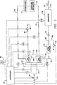
- the compressor stages 12a, 12b are driven through a series of gears 16 which are, in turn, driven directly by an internal combustion engine prime driver 14.
- the angular velocity at which the compressor elements 11 of each of the compressor stages 12a, 12b, will operate at will be a constant ratio of the angular velocity of the internal combustion engine prime driver, depending upon the gearing ratios of the gears 16 used.
- the compressor elements of the latter compressor stages 12b will operate at a higher angular velocity to produce a higher discharge pressure than the compressor elements 11 of the earlier compressor stages 12a.
- An inlet conduit 22 is connected to an inlet port 24 and supplies working fluid to the first stage 12a of the compressor 10.
- An inlet valve 26 regulates fluid flow to the inlet conduit 22.
- the performance of the compressor 10 depends upon its inlet conditions. Therefore, it is common to place a pressure sensor or transducer PT1 and a temperature sensor or transducer T1 in a position to sense fluid pressure and temperature, respectively, within the inlet conduit 22.
- the first stage 12a and the second stage 12b communicate, in series, via an interstage conduit 15.
- An intercooler 17 and a moisture separator 19 are disposed in the interstage conduit to reduce the temperature and the moisture content of the working fluid passing between the two stages to a sufficient condition where it can undergo the further compression of the second stage.
- An interstage temperature sensor or transducer T2 is in fluid communication with the interstage conduit 15.
- the discharge of the last (in this case second) stage 12b is in communication with a discharge conduit 28.
- the discharge conduit 28 connects to the discharge port 30 of the last compressor stage 12b.
- the discharge is in fluid communication via an aftercooler 32 and a check valve 34 to a reservoir 36.
- the aftercooler 32 conditions the working fluid after it exits the compressor 10.
- the check valve 34 limits return working fluid passage once the working fluid passes from the discharge conduit 28 to the reservoir 36, but should not affect passage of the working fluid from the discharge conduit 28 to the reservoir 36.
- a blowoff valve 38 is used to vent compressed air to the atmosphere to keep the compressor pressure ratio from exceeding a predetermined maximum value.
- a service line 40 is in fluid communication with the reservoir 36.
- a service valve 42 controls fluid flow through the service line.
- the service line 40 - service valve 42 combination is constructed in a manner well known in the art so that the user can get access to the working fluid stored in the reservoir 36.
- the angular velocity of the internal combustion engine prime driver 14 is controlled by fuel flow through a fuel line 44, which is regulated by a fuel valve 46 in a manner known in the art. Ideally, the greater the fluid flow through the fuel line 44 to the internal combustion engine prime driver 14, the faster will be the angular velocity of the internal combustion engine prime driver 14 and thereby the angular velocities of the compressor elements 11 of the compressor stages 12a, 12b as described above.
- the position of the fuel valve 46 is directly controlled by the controller 18.
- the angular velocity of the compressor elements 11 in the compressor stages 12a and 12b are controlled by direct input signals from the controller 18 based upon feedback from different sections of the compressor means 10 and/or the internal combustion engine prime driver 14, as described below.
- the controller 18 is of an electronic type, and is preferably microprocessor or microcomputer based.
- a microcomputer which may be used in this application is the INTEL 8OC196 (INTEL is a trademark of the Intel Corporation).
- An interface panel 20 is electronically coupled to the controller 18 in a manner which permits the operator to input setpoints or other operating parameter criteria to the controller 18. To simplify operation, the interface panel of this embodiment permits the operator to select a value for the setpoint reservoir pressure, and the controller 18 will control the operation of the compressor, as described below, to achieve the desired setpoint reservoir pressure in a highly efficient manner.
- temperature sensors or transducers feed input to the controller 18. These temperature sensors include the ambient temperature sensor T1 which determines the ambient temperature of the working fluid just prior to entering the compressor. An interstage temperature sensor T2 determines the temperature of the working fluid between multiple stages (there are only two stages 12a and 12b illustrated in Fig. 1, but for each additional stage connected in series, another interstage temperature sensor T2 becomes necessary). A lube oil temperature sensor T3 senses the temperature of oil in an oil sump (not illustrated) of the compressor 10. An engine coolant temperature sensor T4 determines the temperature of the cooling fluid in the prime driver 14.
- pressure sensors or transducers which determine different pressures whose outputs are fed to the controller 18. These include the inlet pressure sensor PT1 which determines the ambient pressure of the working fluid as sensed by the compressor. A compressor discharge pressure sensor PT2 determines the output pressure of the working fluid in the compressor discharge 30. A reservoir pressure sensor PT3 senses the pressure of the working fluid stored in the reservoir.
- prime driver angular velocity sensor S which determines the angular velocity of the prime driver 14. Since the ratio of angular velocities between the internal combustion engine prime driver 14 and the centrifugal impeller 11 is constant for each stage 12a, 12b (regardless of angular velocity of the internal combustion engine prime driver 14), then the angular velocity of each of the stages can be computed from the angular velocity of the internal combustion engine prime driver 14 as indicated by prime driver angular velocity sensor S.
- the mechanisms which the controller 18 may utilize to control compression of the working fluid by the compressor means 10 include control of the fuel valve 46, control of the inlet valve 26 and control of the blowoff valve 38. Since the fuel valve 46 has such intimate control of operation of the internal combustion engine prime driver 14 and the compressor 10, the control logic of the present invention is especially concerned with the positioning of the fuel valve 46.
- the logic of controlling the angular velocity of the compressor 10 is largely based upon the premise that for each desired pressure at reservoir 36 there is a range of speeds over which the internal combustion engine prime driver may be operated. The higher ends of this range represent inefficient usage of the compressor since the compressor will be producing more fluid than is necessary and the associated mechanical losses will be higher.
- the present invention provides a system to maximize the efficiency by operating the compressor at the minimum angular velocity for which the desired pressure and flow can be maintained considering the prevailing inlet conditions.
- controller 18 in controlling the inlet valve 26 and the blowoff valve 38 are detailed in latter portions of this disclosure. These logic portions do utilize feedback from the logic used in controlling the fuel valve 46.
- the controller 18 is capable of operating the compressor 10 in nine different modes selected by the operator and/or operation of the controller 18.
- the mode of operation of the compressor 10 and the internal combustion engine prime driver are inserted into the logic of the control loops (Figs. 4, 5 and 6) via user input through the interface panel 20.
- the first mode being that the prime driver and the compressor are both in an off state.
- the second mode is that the controller power is on but the machine is not operating.
- Mode three is the startup mode for the internal combustion engine prime driver.
- Mode four is a low idle control for the engine while the compressor is delivering little air.
- Mode five is initial load mode where the internal combustion engine prime driver speed is increased and the compressor is loaded, with the control loops for the inlet valve and the blowoff valve being actuated.
- Mode 6 is used when the prime driver is at typical operating speed while the compressor is in the unloaded state.
- Mode seven has two portions consisting of mode seven-A and mode seven-B.
- Mode seven-A is normal operating mode where the compressor is delivering air at the selected discharge pressure and the engine is running at a constant speed, with pressure control being achieved by modulation of the inlet valve 26.
- Mode seven-B is a speed up mode which is entered when the set point pressure is not achievable with the prime driver operating at normal run speed.
- Mode seven-B incrementally increases the compressor speed by accelerating the internal combustion engine prime driver until either the set point pressure is achieved at the reservoir 36 or the compressor reaches its maximum operating speed.
- Mode eight is a constant speed mode for test purposes in which the inlet valve is kept wide open and the discharge pressure is controlled by the blowoff valve.
- Mode nine is a shutdown state due to any particular alarm, which results in the prime driver decelerating to a stop state.
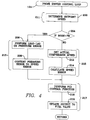
- Fig. 2 illustrates a main loop 100 including four steps.
- the steps of the main program are the Scan Operator Panel step 110, the Display Requested Data (from step 110) step 112, the Check Alarm Limits and Shutdown step 114 and the Process Logic Control Functions step 116.
- the controller repeatedly executes the main loop 100.
- Each 25mSec the execution of the main loop is interrupted by the 25 mSec interrupt loop which is illustrated in Fig. 3. The operation of the 25 mSec loop is described later on.
- the Scan Operator Panel step 110 scans the operator panel for inputs from the operator's panel 20.
- the possible inputs are the start, stop, load, unload compressor functions, the desired operating parameters including compressor discharge pressure (setpoint pressure) and what type of operation the compressor is going to be exposed to.
- the operator panel typically has LCD displays, and the input information may be selected from a scroll type input as is well known in the art.
- the Display Data step 112 displays data as selected from the Scan Operator Panel step 110.
- the data will appear on the operators panel 20.
- the data which appears may be either as directly selected from the operator, or it may display the values of a few functions as is well known in the art.
- the Check Alarm Limits And Shutdowns step 114 checks the values of the pressure, temperature and speed transducers (including transducers which perform functions not described in this specification) and determines if any of the values are sufficient to place the compressor in a dangerous situation.
- the 25mSec interrupt loop 120 illustrated in Fig. 3 contains four steps, which are the Scan All Sensors step 122, the Prime Driver Control Loop step 124, the Inlet Valve Control Loop step 126 and the Blowoff Valve Control Loop step 128.
- the logic of the latter three steps is illustrated in Figs. 4, 5 and 6 respectively, and is described later on.
- the Scan All Sensors step 122 scans the readings of the ambient temperature sensor T1, the interstage temperature sensor T2, the lube oil temperature sensor T3 and the engine coolant temperature sensor T4.
- the Scan All Sensors step also senses the pressure of the inlet pressure sensor PT1, the discharge pressure sensor PT2 and the reservoir pressure sensor PT3 as well as the prime driver angular velocity sensor S.
- the Scan All Sensors step 122 also scans the readings of other pressure, temperature and fluid level transducers in the system (not illustrated but well known in the art) to check for shutdown conditions.
- the Scan All Sensors step 122 contains instructions to shut off the compressor if any of the critical parameters (as sensed by temperature sensors T1, T2, T3 or T4; pressure sensors PT1, PT2 or PT3 as well as speed sensor S, and the other sensors not shown) checked fall outside of predetermined allowable limits.
- the Scan All Sensors step 122 will check whether any temperature or pressure transducer is giving unreliable readings by providing readings outside of predetermined limits which the specific transducer is unlikely to see. For example, when the blowoff valve 38 is closed, the inlet valve 26 is open and the internal combustion engine prime driver 14 is operating at a relatively high rotational velocity, then there should be considerable fluid pressure applied to discharge pressure sensor PT2. If the actual signals under these conditions from PT2, to the controller 18, indicate either a near zero pressure, or a pressure much higher that the compressor is capable of producing, then there is reason to believe that the pressure transducer is giving unreliable indications.
- the controller using the logic contained in the Scan All Sensors step 122 will (if the sensor is a critical one) shut down the compressor and indicate, through the interface panel 20, that the element is acting improperly. Otherwise, it will continue operation of the compressor and indicate on the interface panel 20 the malfunction. An inaccurate indication from each pressure sensor, temperature sensor or speed sensor will result in similar responses by the controller 18 and the interface panel 20.
- the three control loops (the Prime Driver Control loop 124, the Inlet Valve Control loop 126 and the Blowoff Valve Control loop 128, which are illustrated in Figs. 4, 5 and 6, respectively) comprise the logic which the controller 18 utilizes in controlling the efficient production of the setpoint reservoir pressure of the compressor 10.
- the Prime Driver Control loop 124 controls the speed of the internal combustion engine prime driver 14 so that it can operate at or near its minimum angular velocity and still produce the setpoint reservoir pressure.
- the Inlet Valve Control loop 126 controls or modulates the position of the inlet valve 26 as is necessary to load or unload the compressor.
- the Blowoff Valve Control loop 128 controls or modulates the position of the blowoff valve 38 to precisely control the discharge port (and reservoir) pressure, and limits the occurrence of surge or recovery therefrom as is well known.
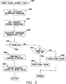
- the Prime Driver Control loop 124 contains seven steps and one decision.
- the seven steps are a Determine Setpoint Speed step 200, a Perform Lead-Lag On Pressure Error step 206, a Convert Pressure Error to Speed Error step 208, a Get Actual Compressor Speed Step 212, a Calculate Speed Error step 214, a Perform PID Control Function step 216 and an Update Output To Fuel Control Valve step 218.
- the Prime Driver Control loop 124 includes four portions.
- the first portion is an Operating Parameter portion 211 which includes the Determine Setpoint Speed step 200.
- the second portion is a pressure portion 213 which includes the Perform Lead-Lag on Pressure Error step 206 and the Convert Pressure Error to Speed Error step 208.
- the third portion is a speed error portion 215 which includes the Get Actual Compressor Speed step 212 and the Calculate Speed Error step 214.
- the fourth portion is the speed adjustment portion 217 which includes the Perform PID Control Function step 216 and the Update Output To Fuel Valve step 218.
- the Determine Setpoint Speed step 200 calculates the minimum angular velocity (G1SET) which the internal combustion engine prime driver is capable of operating at and still provide motive force so the compressor is capable of delivering the setpoint reservoir pressure, as selected by the user on the interface panel 20.
- the Determine Setpoint Speed step 200 receives data from the ambient pressure sensor PT1 and the ambient temperature sensor T1, and determines the setpoint speed approximately once every five minutes.
- the setpoint speed of the internal combustion engine prime driver will vary based upon the mode of operation. In mode 4, for example, the setpoint speed is set to an idle speed.
- the Determine Setpoint Speed (G1SET) step 200 utilizes the results from the Determine G1HP step 350, the Determine GFLOW step 352 and the Determine GSURGE step 354 (determined as described below).
- Decision 356 stores the value of the minimum of G1HP and GFLOW as a minimum value.
- the maximum value of the minimum value and GSURGE are determined by decisions 358 and 360, and the appropriate value is equated to G1SET as illustrated in steps 362, 364 or 366.
- G1HP, GFLOW and GSURGE are specific functions of ambient temperature, ambient pressure and setpoint pressure.
- GFLOW and G1HP are determined by linearly interpolating the results of a performance analysis of the compressor system at different values of ambient pressure, ambient temperature and setpoint pressure.
- G1HP A + B x T1
- GFLOW C + D x T1
- T1 Compressor Inlet Temperature, in Degrees Rankine (Measured From T1).
- A, B, C and D are linear functions of ambient pressure and setpoint pressure, as determined from the performance analysis, which vary depending upon the specifics of the compressor 10 and the internal combustion engine prime driver 14 (as does GSURGE).
- GSURGE is determined from experimentally derived surge line data (not illustrated but well known in the art), which consist of the pressure ratio at surge versus corrected speed for centrifugal compressors.
- the pressure portion 213 includes the Perform Lead - Lag on Pressure Error step 206 and the Convert Pressure Error to Speed Error step 208.
- the Perform Lead - Lag on Pressure Error step 206 is a standard compensation well known in the art.
- the Convert Pressure Error to Speed Error step 208 determines, based upon the pressure error determined from step 206, whether the internal combustion engine prime driver 14 should be accelerated or decelerated to maintain the reservoir pressure at the setpoint.
- the Get Actual Compressor Speed step 212 determines the actual angular velocity of the internal combustion engine prime driver 14 as indicated by the internal combustion engine prime driver speed angular speed sensor S.
- Step 214 calculates the speed error based on the setpoint from step 200.
- the speed error is sent to the Perform PID (Proportional Integral Differential) control function step 216.
- the PID control function calculates the position change of the fuel valve so as to reduce the speed error in a manner well known in the art.
- a term which appropriately describes the PID control function is modulation of the fuel valve.
- the Update Output To The Fuel Valve step 218 applies a signal from the controller 18 to modulate the fuel valve 46 the desired amount as determined from step 216.
- Figure 5 illustrates the Inlet Valve Control loop 126 which contains seven steps and two decisions.
- the seven steps are the Get Setpoint Reservoir Pressure (PT3) step 250, the Get Current System Pressures step 254, the Calculate Pressure Error step 256, the Perform PI Control Function step 258, the Update Positional Signal To Inlet Valve step 260, the Close Inlet Valve step 262 and the Open Inlet Valve step 268.
- PT3 Get Setpoint Reservoir Pressure
- PT3 Get Current System Pressures
- Calculate Pressure Error step 256 the Perform PI Control Function step 258, the Update Positional Signal To Inlet Valve step 260, the Close Inlet Valve step 262 and the Open Inlet Valve step 268.
- the Inlet Valve Control loop 126 permits positioning of the inlet valve depending upon what mode the compressor is being operated in.
- the Get Setpoint Reservoir Pressure step obtains the setpoint reservoir pressure as set by the user on the interface panel 20.
- the setpoint reservoir pressure is used, as described above, in obtaining the setpoint speed in step 200.
- the Get Current System Pressures step 254 determines the values of all the pressures of the pressure sensors or transducers PT1, PT2 and PT3, even though only the first and last are necessary for the operation of the Inlet Valve Control loop 126. The logic of the entire Inlet Valve Control loop will be able to be performed based upon the information of steps 250 and 254.
- the controller operates the system in mode 7a.
- the Perform PI Control Function step 258 is executed to calculate the change in the control signal to the inlet valve.
- the Update Position Signal To Inlet Valve Step 260 is performed to adjust the inlet valve position.
- the controller switches to mode 7b and attempts to achieve it by speeding up. In this case, as in modes 5 and 8, the inlet valve is held full open by performing the Open Inlet Valve step 268.
- the Blowoff Valve Control loop acts to control the pressure ratio (defined as PT2 / PT1 which equals the compressor discharge pressure divided by the compressor inlet pressure) so that it does not exceed a programmed value, PRmax, which is a function of ambient temperature and prime driver speed.
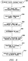
- Fig. 6 illustrates the Blowoff Valve Control Loop 128 which includes seven steps. These include a Get Inlet And Discharge Pressures step 300, a Calculate Pressure Ratio step 302, an Apply Lead-Lag Function to PR step 304, a Determine PRmax step 306, a Calculate Pressure Error step 308, a Perform PI Control Function step 310 and an Update Positional Signal To Blowoff Valve step 312.
- the Get Inlet And Discharge Pressures step 300 obtains an inlet pressure to the first stage 12a of the compressor 12a from PT1, and determines the discharge pressure from the last stage 12b of the compressor via PT2.
- the Calculate Pressure Ratio step 302 determines the pressure ratio by dividing the outlet pressure by the inlet pressure (from the values obtained in step 300).
- the Apply Lead - Lag Function To PR step 304 provides compensation to the pressure ratio to increase the response rate of the control loop.
- the Determine PRmax step 306 determines which maximum pressure ratio (PRmax) the compressor can be run at to avoid the onset of surge considering the ambient temperature, the ambient pressure and the internal combustion engine prime driver speed, in a manner well known in the art.
- the Calculate Pressure Ratio Error step 306 computes the error between the actual pressure ratio and the maximum allowable pressure ratio by subtracting the value obtained in step 306 from the value obtained in step 304.
- the Perform PI Control Function step 310 determines a position that the blowoff valve should be in considering the value of the error obtained in step 308.
- the Update Positional Signal To Blowoff Valve step 312 sends a signal to the blowoff valve 38, based upon the value obtained in step 310.
Abstract
Description
- This invention relates generally to controllers for compressors and more particularly to controllers which are applied to control the operation of internal combustion engine prime driver driven compressors.
- Electronic controllers have been applied to a great variety of circumstances including controlling the angular velocity of compressors which are often used in the process plant industries. The compressors used in industrial applications are typically electrically powered which operate at a constant angular velocity. However, in locations where it is difficult or impractical to provide an external electric source to power the prime driver of the compressor (such as in portable compressor applications), it is highly desirable to have an internal combustion engine driven compressor. While an electrically driven compressor must operate at constant speed, the angular velocity of internal combustion engine prime drivers, by comparison, can be varied to better accommodate changes in ambient conditions, setpoint pressure and other factors. Control of the angular velocity of the internal combustion engine prime drivers is therefore much more complex than with the electrically powered prime drivers (or other constant speed prime drivers).
- Previously, electronic controllers have been applied to control the angular velocity of internal combustion engine prime driver and compressor combinations which are coupled to also drive an electric generator. Since the generator requires a substantially constant angular velocity for proper operation regardless of operating conditions, to maintain a constant frequency, the function of the controller for these internal combustion engine prime driver - centrifugal compressor - generator combinations is to produce a constant angular velocity under all conditions. In the present invention, the angular velocity is maintained at a target value which varies in response to changes in ambient conditions and loading conditions.
- This variation of setting of angular velocity for varying conditions permits the compressor to be run at its most efficient state depending upon the specific loading conditions. In the prior internal combustion engine driven centrifugal compressor-generator combinations, it was often necessary to use considerably more energy than necessary by running the compressor at higher angular velocities than necessary (in cold weather), or, in hot weather, to accept a lower than desired discharge pressure because the speed was too low.
- To produce a truly energy efficient internal combustion engine prime driver - compressor combination capable of maintaining discharge pressure over a wide ambient range, it is important to ensure that the controller has the capability of being programmed to be able to drive the internal combustion engine prime driver at its most efficient angular velocity based upon the present operating mode. It is also important to ensure that the angular velocity of the prime driver remains within close limits to that which the controller is setting it at.
- According to one aspect of the present invention there is provided an apparatus comprising compressor means for compressing a working fluid to be discharged into a reservoir, the compressor means including at least one compressor element; prime driver means, capable of operating at varying angular velocities, for applying motive force to the compressor means; characterised by ratio means, disposed between each compressor element and the prime driver means, for ensuring that a ratio defined as an angular velocity of the compressor element divided by the angular velocity of the prime driver means remains constant; a controllable fuel valve means in communication with the prime driver means, positionable for controlling a fuel flow to the prime driver means; and controller means for positioning the fuel valve means based upon a combination of parameters including a variable setpoint reservoir pressure, ambient pressure and ambient temperature, wherein the prime driver means is operated at an angular velocity at which the actual pressure of the reservoir can be maintained at the setpoint reservoir pressure.
- According to a second aspect of the invention there is provided an apparatus comprising a compressor having a compressor element, an inlet port and a reservoir; a prime driver means rotationally coupled to the compressor element, for driving the compressor, wherein an angular velocity of the prime driver means and an angular velocity of the compressor element are always maintained at a constant ratio; characterised by controller means, for controlling the angular velocity of the prime driver means based upon a group of parameters including a variable setpoint reservoir pressure, ambient temperature and ambient pressure, wherein the prime driver means is operated at an angular velocity at which it is possible to maintain the actual pressure of the working fluid within the reservoir at the setpoint reservoir pressure; computer logic, utilised by the controller means, including a fuel valve control loop; and setpoint means, whereby for each setpoint reservoir pressure setting, the fuel valve control loop computes a distinct value of angular velocity of the prime driver means based upon ambient temperature and ambient pressure and the controller means adjusts the angular velocity of the prime driver means based upon the value of the distinct value.
- According to a third aspect of the invention there is provided a method for controlling angular velocity of a compressor, including the steps of maintaining a ratio between an angular velocity of the compressor divided by an angular velocity of a prime driver means at a constant ratio; adjusting an angular velocity of the prime driver means by regulating a fuel flow to the prime driver means; sensing an ambient temperature, an ambient pressure and a setpoint reservoir pressure; computing a desired fluid flow to the prime driver means for achieving the setpoint reservoir pressure; and setting the fluid flow to a desired fluid flow.
- For a better understanding of the invention and to show how the same may be carried into effect, reference will now be made, by way of example, to the accompanying drawings, in which:-
- Fig. 1 is a schematic view illustrating an embodiment of the controller and associated connections for a centrifugal compressor;
- Fig. 2 is a flow chart containing the logic for one embodiment of the main loop for the logic contained in the controller;
- Fig. 3 is a flow chart for an interrupt sequence;
- Fig. 4 is a flow chart for a prime driver control loop;
- Fig. 5 is a flow chart for an inlet valve control loop;
- Fig. 6 is a flow chart for a blowoff valve control loop;
- Fig. 7 is a cross sectional view of a compressor stage, incorporating the centrifugal impeller and diffuser portion; and
- Fig. 8 is a flowchart of the Determine
Setpoint Speed step 200 of Fig. 4. - Referring to Fig. 1, the
compressor stages gears 16 which are, in turn, driven directly by an internal combustionengine prime driver 14. The angular velocity at which thecompressor elements 11 of each of thecompressor stages gears 16 used. Typically, the compressor elements of thelatter compressor stages 12b will operate at a higher angular velocity to produce a higher discharge pressure than thecompressor elements 11 of theearlier compressor stages 12a. - In internal combustion engine prime drivers, the angular velocity is affected by ambient temperatures and ambient pressures as well as loads. Therefore, limiting the fluctuation of the angular velocity of internal combustion engine prime drivers over time is difficult. Diesel prime drivers are preferred over other internal combustion engine prime drivers, for many applications, due to their increased reliability and economy.
- An
inlet conduit 22 is connected to aninlet port 24 and supplies working fluid to thefirst stage 12a of thecompressor 10. Aninlet valve 26 regulates fluid flow to theinlet conduit 22. The performance of thecompressor 10 depends upon its inlet conditions. Therefore, it is common to place a pressure sensor or transducer PT1 and a temperature sensor or transducer T1 in a position to sense fluid pressure and temperature, respectively, within theinlet conduit 22. - The
first stage 12a and thesecond stage 12b communicate, in series, via aninterstage conduit 15. Anintercooler 17 and amoisture separator 19 are disposed in the interstage conduit to reduce the temperature and the moisture content of the working fluid passing between the two stages to a sufficient condition where it can undergo the further compression of the second stage. An interstage temperature sensor or transducer T2 is in fluid communication with theinterstage conduit 15. - The discharge of the last (in this case second)
stage 12b is in communication with adischarge conduit 28. Thedischarge conduit 28 connects to thedischarge port 30 of thelast compressor stage 12b. The discharge is in fluid communication via anaftercooler 32 and acheck valve 34 to areservoir 36. Theaftercooler 32 conditions the working fluid after it exits thecompressor 10. Thecheck valve 34 limits return working fluid passage once the working fluid passes from thedischarge conduit 28 to thereservoir 36, but should not affect passage of the working fluid from thedischarge conduit 28 to thereservoir 36. Also in fluid communication with thedischarge conduit 28 is ablowoff valve 38. Theblowoff valve 38 is used to vent compressed air to the atmosphere to keep the compressor pressure ratio from exceeding a predetermined maximum value. - A
service line 40 is in fluid communication with thereservoir 36. Aservice valve 42 controls fluid flow through the service line. The service line 40 -service valve 42 combination is constructed in a manner well known in the art so that the user can get access to the working fluid stored in thereservoir 36. - The angular velocity of the internal combustion engine
prime driver 14 is controlled by fuel flow through afuel line 44, which is regulated by afuel valve 46 in a manner known in the art. Ideally, the greater the fluid flow through thefuel line 44 to the internal combustionengine prime driver 14, the faster will be the angular velocity of the internal combustionengine prime driver 14 and thereby the angular velocities of thecompressor elements 11 of thecompressor stages fuel valve 46 is directly controlled by thecontroller 18. In this manner, the angular velocity of thecompressor elements 11 in thecompressor stages controller 18 based upon feedback from different sections of the compressor means 10 and/or the internal combustionengine prime driver 14, as described below. - The
controller 18 is of an electronic type, and is preferably microprocessor or microcomputer based. A microcomputer which may be used in this application is the INTEL 8OC196 (INTEL is a trademark of the Intel Corporation). Aninterface panel 20 is electronically coupled to thecontroller 18 in a manner which permits the operator to input setpoints or other operating parameter criteria to thecontroller 18. To simplify operation, the interface panel of this embodiment permits the operator to select a value for the setpoint reservoir pressure, and thecontroller 18 will control the operation of the compressor, as described below, to achieve the desired setpoint reservoir pressure in a highly efficient manner. - Several temperature sensors or transducers feed input to the
controller 18. These temperature sensors include the ambient temperature sensor T1 which determines the ambient temperature of the working fluid just prior to entering the compressor. An interstage temperature sensor T2 determines the temperature of the working fluid between multiple stages (there are only twostages compressor 10. An engine coolant temperature sensor T4 determines the temperature of the cooling fluid in theprime driver 14. - There are several pressure sensors or transducers which determine different pressures whose outputs are fed to the
controller 18. These include the inlet pressure sensor PT1 which determines the ambient pressure of the working fluid as sensed by the compressor. A compressor discharge pressure sensor PT2 determines the output pressure of the working fluid in thecompressor discharge 30. A reservoir pressure sensor PT3 senses the pressure of the working fluid stored in the reservoir. - There is a prime driver angular velocity sensor S which determines the angular velocity of the
prime driver 14. Since the ratio of angular velocities between the internal combustion engineprime driver 14 and thecentrifugal impeller 11 is constant for eachstage prime driver 14 as indicated by prime driver angular velocity sensor S. - The mechanisms which the
controller 18 may utilize to control compression of the working fluid by the compressor means 10 include control of thefuel valve 46, control of theinlet valve 26 and control of theblowoff valve 38. Since thefuel valve 46 has such intimate control of operation of the internal combustion engineprime driver 14 and thecompressor 10, the control logic of the present invention is especially concerned with the positioning of thefuel valve 46. - The logic of controlling the angular velocity of the
compressor 10 is largely based upon the premise that for each desired pressure atreservoir 36 there is a range of speeds over which the internal combustion engine prime driver may be operated. The higher ends of this range represent inefficient usage of the compressor since the compressor will be producing more fluid than is necessary and the associated mechanical losses will be higher. The difficulty arises in controlling prior internal combustion engine prime drivers to constantly operate at or near the most efficient value of angular velocities regardless of changing ambient temperature and ambient pressure (since these values may fluctuate). The present invention provides a system to maximize the efficiency by operating the compressor at the minimum angular velocity for which the desired pressure and flow can be maintained considering the prevailing inlet conditions. - The logic utilized by the
controller 18 in controlling theinlet valve 26 and theblowoff valve 38 are detailed in latter portions of this disclosure. These logic portions do utilize feedback from the logic used in controlling thefuel valve 46. - The
controller 18 is capable of operating thecompressor 10 in nine different modes selected by the operator and/or operation of thecontroller 18. The mode of operation of thecompressor 10 and the internal combustion engine prime driver are inserted into the logic of the control loops (Figs. 4, 5 and 6) via user input through theinterface panel 20. The first mode being that the prime driver and the compressor are both in an off state. The second mode is that the controller power is on but the machine is not operating. Mode three is the startup mode for the internal combustion engine prime driver. Mode four is a low idle control for the engine while the compressor is delivering little air. Mode five is initial load mode where the internal combustion engine prime driver speed is increased and the compressor is loaded, with the control loops for the inlet valve and the blowoff valve being actuated. Mode 6 is used when the prime driver is at typical operating speed while the compressor is in the unloaded state. - Mode seven has two portions consisting of mode seven-A and mode seven-B. Mode seven-A is normal operating mode where the compressor is delivering air at the selected discharge pressure and the engine is running at a constant speed, with pressure control being achieved by modulation of the
inlet valve 26. Mode seven-B is a speed up mode which is entered when the set point pressure is not achievable with the prime driver operating at normal run speed. Mode seven-B incrementally increases the compressor speed by accelerating the internal combustion engine prime driver until either the set point pressure is achieved at thereservoir 36 or the compressor reaches its maximum operating speed. Mode eight is a constant speed mode for test purposes in which the inlet valve is kept wide open and the discharge pressure is controlled by the blowoff valve. Mode nine is a shutdown state due to any particular alarm, which results in the prime driver decelerating to a stop state. - The
controller 18 controls the operation of the compressor utilizing the logic flowcharted in Figs 2-6 and 8. Fig. 2 illustrates amain loop 100 including four steps. The steps of the main program are the ScanOperator Panel step 110, the Display Requested Data (from step 110)step 112, the Check Alarm Limits andShutdown step 114 and the Process Logic Control Functionsstep 116. The controller repeatedly executes themain loop 100. Each 25mSec the execution of the main loop is interrupted by the 25 mSec interrupt loop which is illustrated in Fig. 3. The operation of the 25 mSec loop is described later on. - The Scan
Operator Panel step 110 scans the operator panel for inputs from the operator'spanel 20. The possible inputs are the start, stop, load, unload compressor functions, the desired operating parameters including compressor discharge pressure (setpoint pressure) and what type of operation the compressor is going to be exposed to. The operator panel typically has LCD displays, and the input information may be selected from a scroll type input as is well known in the art. - The
Display Data step 112 displays data as selected from the ScanOperator Panel step 110. The data will appear on theoperators panel 20. The data which appears may be either as directly selected from the operator, or it may display the values of a few functions as is well known in the art. - The Check Alarm Limits And Shutdowns step 114 checks the values of the pressure, temperature and speed transducers (including transducers which perform functions not described in this specification) and determines if any of the values are sufficient to place the compressor in a dangerous situation.
- The 25mSec interrupt
loop 120 illustrated in Fig. 3 contains four steps, which are the ScanAll Sensors step 122, the Prime DriverControl Loop step 124, the Inlet ValveControl Loop step 126 and the Blowoff ValveControl Loop step 128. The logic of the latter three steps is illustrated in Figs. 4, 5 and 6 respectively, and is described later on. - The Scan All Sensors step 122 scans the readings of the ambient temperature sensor T1, the interstage temperature sensor T2, the lube oil temperature sensor T3 and the engine coolant temperature sensor T4. The Scan All Sensors step also senses the pressure of the inlet pressure sensor PT1, the discharge pressure sensor PT2 and the reservoir pressure sensor PT3 as well as the prime driver angular velocity sensor S.
- The Scan
All Sensors step 122, also scans the readings of other pressure, temperature and fluid level transducers in the system (not illustrated but well known in the art) to check for shutdown conditions. The Scan All Sensors step 122 contains instructions to shut off the compressor if any of the critical parameters (as sensed by temperature sensors T1, T2, T3 or T4; pressure sensors PT1, PT2 or PT3 as well as speed sensor S, and the other sensors not shown) checked fall outside of predetermined allowable limits. - The Scan All Sensors step 122 will check whether any temperature or pressure transducer is giving unreliable readings by providing readings outside of predetermined limits which the specific transducer is unlikely to see. For example, when the
blowoff valve 38 is closed, theinlet valve 26 is open and the internal combustion engineprime driver 14 is operating at a relatively high rotational velocity, then there should be considerable fluid pressure applied to discharge pressure sensor PT2. If the actual signals under these conditions from PT2, to thecontroller 18, indicate either a near zero pressure, or a pressure much higher that the compressor is capable of producing, then there is reason to believe that the pressure transducer is giving unreliable indications. Under these conditions, the controller using the logic contained in the Scan All Sensors step 122 will (if the sensor is a critical one) shut down the compressor and indicate, through theinterface panel 20, that the element is acting improperly. Otherwise, it will continue operation of the compressor and indicate on theinterface panel 20 the malfunction. An inaccurate indication from each pressure sensor, temperature sensor or speed sensor will result in similar responses by thecontroller 18 and theinterface panel 20. - The three control loops (the Prime
Driver Control loop 124, the InletValve Control loop 126 and the BlowoffValve Control loop 128, which are illustrated in Figs. 4, 5 and 6, respectively) comprise the logic which thecontroller 18 utilizes in controlling the efficient production of the setpoint reservoir pressure of thecompressor 10. The PrimeDriver Control loop 124 controls the speed of the internal combustion engineprime driver 14 so that it can operate at or near its minimum angular velocity and still produce the setpoint reservoir pressure. The InletValve Control loop 126 controls or modulates the position of theinlet valve 26 as is necessary to load or unload the compressor. The BlowoffValve Control loop 128 controls or modulates the position of theblowoff valve 38 to precisely control the discharge port (and reservoir) pressure, and limits the occurrence of surge or recovery therefrom as is well known. - The Prime
Driver Control loop 124 contains seven steps and one decision. The seven steps are a DetermineSetpoint Speed step 200, a Perform Lead-Lag OnPressure Error step 206, a Convert Pressure Error toSpeed Error step 208, a Get ActualCompressor Speed Step 212, a CalculateSpeed Error step 214, a Perform PIDControl Function step 216 and an Update Output To FuelControl Valve step 218. The one decision is the If Mode =7b decision 204. - The Prime
Driver Control loop 124 includes four portions. The first portion is anOperating Parameter portion 211 which includes the DetermineSetpoint Speed step 200. The second portion is apressure portion 213 which includes the Perform Lead-Lag onPressure Error step 206 and the Convert Pressure Error toSpeed Error step 208. The third portion is aspeed error portion 215 which includes the Get ActualCompressor Speed step 212 and the CalculateSpeed Error step 214. The fourth portion is thespeed adjustment portion 217 which includes the Perform PIDControl Function step 216 and the Update Output ToFuel Valve step 218. - The Determine
Setpoint Speed step 200 calculates the minimum angular velocity (G1SET) which the internal combustion engine prime driver is capable of operating at and still provide motive force so the compressor is capable of delivering the setpoint reservoir pressure, as selected by the user on theinterface panel 20. The DetermineSetpoint Speed step 200 receives data from the ambient pressure sensor PT1 and the ambient temperature sensor T1, and determines the setpoint speed approximately once every five minutes. - The setpoint speed of the internal combustion engine prime driver will vary based upon the mode of operation. In mode 4, for example, the setpoint speed is set to an idle speed. When the internal combustion engine prime driver and compressor are operating in mode 7a, the setpoint speed (G1SET) is calculated as follows:
G1SET = MAX [MIN (G1HP, GFLOW), GSURGE]
where, - G1SET
- = Setpoint Speed
- G1HP
- = Speed at which the required engine horsepower is equal to a predetermined percentage of the rated engine horsepower (one horsepower = 745.7 W)
- GFLOW
- = Speed at which the delivered compressor flow is equal to the rated flow
- GSURGE
- = The minimum speed for which an adequate surge margin is maintained. GSURGE is only applicable to centrifugal compressors and pumps. When this control system is applied to non-centrifugal compressors or pumps driven by internal combustion engine prime drivers, the GSURGE portion of this and the following equations is omitted.
- As indicated in the above equation and Fig. 8, the Determine Setpoint Speed (G1SET)
step 200 utilizes the results from the DetermineG1HP step 350, the DetermineGFLOW step 352 and the Determine GSURGE step 354 (determined as described below).Decision 356 stores the value of the minimum of G1HP and GFLOW as a minimum value. The maximum value of the minimum value and GSURGE are determined bydecisions steps - G1HP, GFLOW and GSURGE are specific functions of ambient temperature, ambient pressure and setpoint pressure. GFLOW and G1HP are determined by linearly interpolating the results of a performance analysis of the compressor system at different values of ambient pressure, ambient temperature and setpoint pressure. In general:
G1HP = A + B x T1, and
GFLOW = C + D x T1, where
T1 = Compressor Inlet Temperature, in Degrees Rankine (Measured From T1). - A, B, C and D are linear functions of ambient pressure and setpoint pressure, as determined from the performance analysis, which vary depending upon the specifics of the
compressor 10 and the internal combustion engine prime driver 14 (as does GSURGE). GSURGE is determined from experimentally derived surge line data (not illustrated but well known in the art), which consist of the pressure ratio at surge versus corrected speed for centrifugal compressors. - GSURGE
- = FC x Squareroot(T1/Z) x GC, where
- Z
- = A constant.
- FC
- = Surge Margin Factor, Generally 1.08 or larger; and
- GC
- = Corrected Speed at which surge occurs at the required pressure ratio (REQD_PR).
- REQD_PR
- = Required Pressure Ratio = (PSET + DP2)/PT1, where
- PSET
- = Setpoint Reservoir Pressure;
- DP2
- = Discharge Conduit pressure drop (Measured difference between PT3 and PT2); and
- PT1
- = Ambient Pressure at Compressor Inlet (Measured from PT1).
- The
pressure portion 213 includes the Perform Lead - Lag onPressure Error step 206 and the Convert Pressure Error toSpeed Error step 208. The Perform Lead - Lag onPressure Error step 206 is a standard compensation well known in the art. The Convert Pressure Error toSpeed Error step 208 determines, based upon the pressure error determined fromstep 206, whether the internal combustion engineprime driver 14 should be accelerated or decelerated to maintain the reservoir pressure at the setpoint. - In the
speed error portion 215, the Get ActualCompressor Speed step 212 determines the actual angular velocity of the internal combustion engineprime driver 14 as indicated by the internal combustion engine prime driver speed angular speedsensor S. Step 214 calculates the speed error based on the setpoint fromstep 200. - In the
speed adjustment portion 217, the speed error is sent to the Perform PID (Proportional Integral Differential)control function step 216. The PID control function calculates the position change of the fuel valve so as to reduce the speed error in a manner well known in the art. A term which appropriately describes the PID control function is modulation of the fuel valve. The Update Output To TheFuel Valve step 218 applies a signal from thecontroller 18 to modulate thefuel valve 46 the desired amount as determined fromstep 216. - Figure 5 illustrates the Inlet
Valve Control loop 126 which contains seven steps and two decisions. The seven steps are the Get Setpoint Reservoir Pressure (PT3)step 250, the Get Current System Pressures step 254, the CalculatePressure Error step 256, the Perform PIControl Function step 258, the Update Positional Signal ToInlet Valve step 260, the CloseInlet Valve step 262 and the OpenInlet Valve step 268. - The Inlet
Valve Control loop 126 permits positioning of the inlet valve depending upon what mode the compressor is being operated in. The Get Setpoint Reservoir Pressure step obtains the setpoint reservoir pressure as set by the user on theinterface panel 20. The setpoint reservoir pressure is used, as described above, in obtaining the setpoint speed instep 200. - The Get Current System Pressures step 254 determines the values of all the pressures of the pressure sensors or transducers PT1, PT2 and PT3, even though only the first and last are necessary for the operation of the Inlet
Valve Control loop 126. The logic of the entire Inlet Valve Control loop will be able to be performed based upon the information ofsteps - Under normal conditions the controller operates the system in mode 7a. In this case, the Perform PI
Control Function step 258 is executed to calculate the change in the control signal to
the inlet valve. Next, the Update Position Signal ToInlet Valve Step 260 is performed to adjust the inlet valve position. - If the setpoint pressure cannot be achieved in mode 7a, the controller switches to mode 7b and attempts to achieve it by speeding up. In this case, as in modes 5 and 8, the inlet valve is held full open by performing the Open
Inlet Valve step 268. - If the mode is modes 3, 4, 6 or 9 when the Inlet
Valve Control loop 126 is entered, then the logic of the CloseInlet Valve step 262 will be performed. - The Blowoff Valve Control loop acts to control the pressure ratio (defined as PT2 / PT1 which equals the compressor discharge pressure divided by the compressor inlet pressure) so that it does not exceed a programmed value, PRmax, which is a function of ambient temperature and prime driver speed. Fig. 6 illustrates the Blowoff
Valve Control Loop 128 which includes seven steps. These include a Get Inlet And Discharge Pressures step 300, a CalculatePressure Ratio step 302, an Apply Lead-Lag Function toPR step 304, a DeterminePRmax step 306, a CalculatePressure Error step 308, a Perform PIControl Function step 310 and an Update Positional Signal ToBlowoff Valve step 312. - The Get Inlet And Discharge Pressures step 300 obtains an inlet pressure to the
first stage 12a of thecompressor 12a from PT1, and determines the discharge pressure from thelast stage 12b of the compressor via PT2. The CalculatePressure Ratio step 302 determines the pressure ratio by dividing the outlet pressure by the inlet pressure (from the values obtained in step 300). - The Apply Lead - Lag Function To
PR step 304 provides compensation to the pressure ratio to increase the response rate of the control loop. The DeterminePRmax step 306 determines which maximum pressure ratio (PRmax) the compressor can be run at to avoid the onset of surge considering the ambient temperature, the ambient pressure and the internal combustion engine prime driver speed, in a manner well known in the art. The Calculate PressureRatio Error step 306 computes the error between the actual pressure ratio and the maximum allowable pressure ratio by subtracting the value obtained instep 306 from the value obtained instep 304. The Perform PIControl Function step 310 determines a position that the blowoff valve should be in considering the value of the error obtained instep 308. The Update Positional Signal ToBlowoff Valve step 312 sends a signal to theblowoff valve 38, based upon the value obtained instep 310.
A
Claims (25)
- An apparatus comprising compressor means for compressing a working fluid to be discharged into a reservoir, the compressor means including at least one compressor element; prime driver means, capable of operating at varying angular velocities, for applying motive force to the compressor means; characterised by ratio means, disposed between each compressor element and the prime driver means, for ensuring that a ratio defined as an angular velocity of the compressor element divided by the angular velocity of the prime driver means remains constant; a controllable fuel valve means in communication with the prime driver means, positionable for controlling a fuel flow to the prime driver means; and controller means for positioning the fuel valve means based upon a combination of parameters including a variable setpoint reservoir pressure, ambient pressure and ambient temperature, wherein the prime driver means is operated at an angular velocity at which the actual pressure of the reservoir can be maintained at the setpoint reservoir pressure.
- An apparatus comprising a compressor having a compressor element, an inlet port and a reservoir; a prime driver means rotationally coupled to the compressor element, for driving the compressor, wherein an angular velocity of the prime driver means and an angular velocity of the compressor element are always maintained at a constant ratio; characterised by controller means, for controlling the angular velocity of the prime driver means based upon a group of parameters including a variable setpoint reservoir pressure, ambient temperature and ambient pressure, wherein the prime driver means is operated at an angular velocity at which it is possible to maintain the actual pressure of the working fluid within the reservoir at the setpoint reservoir pressure; computer logic, utilised by the controller means, including a fuel valve control loop; and setpoint means, whereby for each setpoint reservoir pressure setting, the fuel valve control loop computes a distinct value of angular velocity of the prime driver means based upon ambient temperature and ambient pressure and the controller means adjusts the angular velocity of the prime driver means based upon the value of the distinct value.
- An apparatus according to claim 1, wherein the combination of parameters further comprises a difference between the variable setpoint reservoir pressure and a present pressure at the reservoir.
- An apparatus according to claim 1, 2 or 3, wherein the compressor means further comprises a discharge conduit partially containing fluid passing from the compressor discharge; and a positional blowoff valve means in communication with the discharge conduit, for permitting fluid passage therefrom to the atmosphere.
- An apparatus according to claim 4, wherein the controller means also positions the positional blowoff valve means.
- An apparatus according to any one of the preceding claims, wherein the compressor means further comprises an adjustable inlet valve means for controlling fluid flow to the compressor means.
- An apparatus according to claim 6, wherein the controller means also positions the adjustable inlet valve means.
- An apparatus according to claims 4 to 7 without claim 2, wherein logic of the controller means includes a fuel valve control loop for positioning one of the blowoff valve means and the inlet valve means based on the setpoint reservoir pressure and the present pressure in the reservoir.
- An apparatus according to any one of the preceding claims, wherein the controller means is electronically based.
- An apparatus according to claim 9, wherein the controller means is microprocessor based.
- An apparatus according to any one of the preceding claims, wherein the controller means further comprises setpoint adjustment means for increasing fluid pressure in the reservoir when the compressor has been operating for a specified period and the fluid pressure in the reservoir has not achieved the setpoint reservoir pressure.
- An apparatus according to any one of the preceding claims, wherein the ratio means includes a gear arrangement.
- An apparatus according to any one of the preceding claims and being arranged such that, for a given variable setpoint reservoir pressure, the angular velocity will be determined based upon the ambient pressure and the ambient temperature.
- An apparatus according to any one of the preceding claims, wherein the controller means is constructed to perform diagnostics of the prime driver means.
- An apparatus according to any one of the preceding claims, wherein the prime driver means is internal combustion engine powered.
- An apparatus according to any one of the preceding claims, wherein the prime driver means is arranged to operate at substantially the lowest angular velocity possible to maintain the actual pressure of the reservoir at the setpoint reservoir pressure.
- An apparatus according to claim 2, wherein the computer logic further comprises an inlet valve control loop and a blowoff valve control loop.
- An apparatus according to claim 2 or 17, wherein the computer logic further contains operational modes means for the user to determine the mode which the compressor means is operating, wherein the logic of the inlet valve control loop and the blowoff valve control loop are based upon the setpoint reservoir pressure setting, the actual pressure of the reservoir and the operational mode means.
- An apparatus according to any one of the preceding claims and further comprising an interface panel means for permitting the user to alter the setpoint reservoir pressure setting.
- A method for controlling angular velocity of a compressor, including the steps of maintaining a ratio between an angular velocity of the compressor divided by an angular velocity of a prime driver means at a constant ratio; adjusting an angular velocity of the prime driver means by regulating a fuel flow to the prime driver means; sensing an ambient temperature, an ambient pressure and a setpoint reservoir pressure; computing a desired fluid flow to the prime driver means for achieving the setpoint reservoir pressure; and setting the fluid flow to a desired fluid flow.
- A method according to claim 20, wherein the desired fluid flow is substantially the lowest fluid flow which will accomplish the setpoint reservoir pressure.
- A method according to claim 20 or 21, wherein the computing step utilises a microprocessor.
- A method according to claim 20 or 21, wherein the computing step utilises a microcomputer.
- A method according to claim 20, 21, 22 or 23, wherein the angular velocity adjusting step further comprises the steps of determining a G1HP value and a GFLOW value; and assigning the minimum of the G1HP and GFLOW values as a minimum value.
- A method according to claim 20, 21, 22 or 23, wherein the angular velocity adjusting step further comprises the steps of determining a GSURGE value; and assigning the maximum of the minimum value and the GSURGE value as a maximum value.
Applications Claiming Priority (2)
| Application Number | Priority Date | Filing Date | Title |
|---|---|---|---|
| US07/881,948 US5224836A (en) | 1992-05-12 | 1992-05-12 | Control system for prime driver of compressor and method |
| US881948 | 1992-05-12 |
Publications (2)
| Publication Number | Publication Date |
|---|---|
| EP0570114A1 true EP0570114A1 (en) | 1993-11-18 |
| EP0570114B1 EP0570114B1 (en) | 1996-12-04 |
Family
ID=25379547
Family Applications (1)
| Application Number | Title | Priority Date | Filing Date |
|---|---|---|---|
| EP93303012A Expired - Lifetime EP0570114B1 (en) | 1992-05-12 | 1993-04-19 | Control system for prime driver of compressor and method |
Country Status (4)
| Country | Link |
|---|---|
| US (1) | US5224836A (en) |
| EP (1) | EP0570114B1 (en) |
| JP (1) | JP2591898B2 (en) |
| DE (1) | DE69306301T2 (en) |
Cited By (2)
| Publication number | Priority date | Publication date | Assignee | Title |
|---|---|---|---|---|
| WO2002025115A1 (en) * | 2000-09-25 | 2002-03-28 | Compair Uk Limited | Multi-stage screw compressor |
| EP1427941A1 (en) * | 2001-08-30 | 2004-06-16 | Ingersoll-Rand Company | Engine driven compressor |
Families Citing this family (24)
| Publication number | Priority date | Publication date | Assignee | Title |
|---|---|---|---|---|
| US5386873A (en) * | 1993-06-09 | 1995-02-07 | Ingersoll-Rand Company | Cooling system for engine-driven multi-stage centrifugal compressor |
| EP0863313A1 (en) * | 1997-03-04 | 1998-09-09 | Anest Iwata Corporation | Two stage scroll compressor |
| US5967757A (en) * | 1997-03-24 | 1999-10-19 | Gunn; John T. | Compressor control system and method |
| CA2308624C (en) * | 1997-10-28 | 2005-07-26 | Coltec Industries, Inc. | Compressor system and method and control for same |
| JP3929185B2 (en) * | 1998-05-20 | 2007-06-13 | 株式会社荏原製作所 | Vacuum exhaust apparatus and method |
| US6077052A (en) * | 1998-09-02 | 2000-06-20 | Ingersoll-Rand Company | Fluid compressor aftercooler temperature control system and method |
| WO2000019105A1 (en) * | 1998-09-25 | 2000-04-06 | Honeywell Inc. | Multiple centrifugal air compressor system control |
| US6993418B2 (en) * | 1999-03-16 | 2006-01-31 | Sigma Systems Corporation | Method and apparatus for latent temperature control for a device under test |
| US6449534B1 (en) | 1999-03-16 | 2002-09-10 | Sigma Systems Corporation | Method and apparatus for optimizing environmental temperature for a device under test |
| US6534958B1 (en) | 1999-08-16 | 2003-03-18 | Coleman Powermate, Inc. | System that supplies electrical power and compressed air with throttle control |
| BR0103443A (en) * | 2001-08-21 | 2004-03-09 | Petroleo Brasileiro Sa | Multiphase Pumping System and Method |
| US6981838B2 (en) * | 2002-02-26 | 2006-01-03 | Southern Gas Association Gas Machinery Reserach Council | Method and apparatus for detecting the occurrence of surge in a centrifugal compressor |
| US6939110B2 (en) * | 2002-11-06 | 2005-09-06 | Clarke Engineering Technologies, Inc. | Control system for I.C. engine driven blower |
| KR100922587B1 (en) * | 2002-11-12 | 2009-10-21 | 한국항공우주산업 주식회사 | Leakage testing apparatus for airtight container |
| US7275916B2 (en) * | 2003-11-24 | 2007-10-02 | Southwest Research Institute | Integrated engine/compressor control for gas transmission compressors |
| US20070189905A1 (en) * | 2006-02-13 | 2007-08-16 | Ingersoll-Rand Company | Multi-stage compression system and method of operating the same |
| BE1017600A3 (en) * | 2007-05-15 | 2009-01-13 | Atlas Copco Airpower Nv | METHOD FOR CONTROLLING A TURBO COMPRESSOR. |
| US8308439B2 (en) * | 2007-07-20 | 2012-11-13 | Lummus Technology Inc. | Method and apparatus for resisting disabling fouling of compressors in multistage compression systems |
| US8342150B2 (en) * | 2009-02-11 | 2013-01-01 | Illinois Tool Works Inc | Compressor control for determining maximum pressure, minimum pressure, engine speed, and compressor loading |
| EP2325494B1 (en) * | 2009-11-19 | 2017-04-12 | General Electric Company | Torque-based sensor and control method for varying gas-liquid fractions of fluids for turbomachines |
| NZ602759A (en) * | 2010-04-20 | 2014-11-28 | Sandvik Intellectual Property | Air compressor system and method of operation |
| FR3099806B1 (en) * | 2019-08-07 | 2021-09-03 | Safran Power Units | ANTI-PUMPING REGULATION OF A CHARGE COMPRESSOR EQUIPPING AN AUXILIARY POWER UNIT |
| DE102020205531A1 (en) | 2020-04-30 | 2021-11-04 | Mahle International Gmbh | Side channel compressor for compressing gas |
| DE102020205533A1 (en) * | 2020-04-30 | 2021-11-04 | Mahle International Gmbh | Side channel compressor for compressing a gas |
Citations (4)
| Publication number | Priority date | Publication date | Assignee | Title |
|---|---|---|---|---|
| DE3609399A1 (en) * | 1985-03-23 | 1986-10-16 | Barmag Barmer Maschinenfabrik Ag, 5630 Remscheid | Hydraulic system |
| EP0209499A2 (en) * | 1985-06-10 | 1987-01-21 | Institut Cerac S.A. | A compressor plant |
| DE3611553C1 (en) * | 1986-04-07 | 1987-07-23 | Orenstein & Koppel Ag | Arrangement for operating a diesel-hydraulic drive |
| US4765150A (en) * | 1987-02-09 | 1988-08-23 | Margaux Controls, Inc. | Continuously variable capacity refrigeration system |
Family Cites Families (8)
| Publication number | Priority date | Publication date | Assignee | Title |
|---|---|---|---|---|
| US4191511A (en) * | 1976-07-26 | 1980-03-04 | Phillips Petroleum Company | Compressor control |
| US4232997A (en) * | 1978-04-27 | 1980-11-11 | Grimmer Schmidt Corp. | Method and apparatus for controlling compressors |
| US4486148A (en) * | 1979-10-29 | 1984-12-04 | Michigan Consolidated Gas Company | Method of controlling a motive power and fluid driving system |
| US4560322A (en) * | 1982-05-13 | 1985-12-24 | Ulf Andersson | Regulator for regulating the output pressure of a motor driven pump |
| US4496286A (en) * | 1983-07-18 | 1985-01-29 | J-W Operating Company | Control system for engine-driven compressor unit and method of operation thereof |
| JPH0240942U (en) * | 1988-09-13 | 1990-03-20 | ||
| US4940391A (en) * | 1988-11-07 | 1990-07-10 | Westinghouse Electric Corp. | Compressor surge detection system |
| US4926942A (en) * | 1989-02-22 | 1990-05-22 | Profrock Jr William P | Method for reducing sand production in submersible-pump wells |
-
1992
- 1992-05-12 US US07/881,948 patent/US5224836A/en not_active Expired - Lifetime
-
1993
- 1993-04-19 EP EP93303012A patent/EP0570114B1/en not_active Expired - Lifetime
- 1993-04-19 DE DE69306301T patent/DE69306301T2/en not_active Expired - Fee Related
- 1993-05-12 JP JP5110662A patent/JP2591898B2/en not_active Expired - Fee Related
Patent Citations (4)
| Publication number | Priority date | Publication date | Assignee | Title |
|---|---|---|---|---|
| DE3609399A1 (en) * | 1985-03-23 | 1986-10-16 | Barmag Barmer Maschinenfabrik Ag, 5630 Remscheid | Hydraulic system |
| EP0209499A2 (en) * | 1985-06-10 | 1987-01-21 | Institut Cerac S.A. | A compressor plant |
| DE3611553C1 (en) * | 1986-04-07 | 1987-07-23 | Orenstein & Koppel Ag | Arrangement for operating a diesel-hydraulic drive |
| US4765150A (en) * | 1987-02-09 | 1988-08-23 | Margaux Controls, Inc. | Continuously variable capacity refrigeration system |
Cited By (3)
| Publication number | Priority date | Publication date | Assignee | Title |
|---|---|---|---|---|
| WO2002025115A1 (en) * | 2000-09-25 | 2002-03-28 | Compair Uk Limited | Multi-stage screw compressor |
| EP1427941A1 (en) * | 2001-08-30 | 2004-06-16 | Ingersoll-Rand Company | Engine driven compressor |
| EP1427941A4 (en) * | 2001-08-30 | 2006-04-05 | Ingersoll Rand Co | Engine driven compressor |
Also Published As
| Publication number | Publication date |
|---|---|
| US5224836A (en) | 1993-07-06 |
| JP2591898B2 (en) | 1997-03-19 |
| EP0570114B1 (en) | 1996-12-04 |
| DE69306301T2 (en) | 1997-06-12 |
| DE69306301D1 (en) | 1997-01-16 |
| JPH0650268A (en) | 1994-02-22 |
Similar Documents
| Publication | Publication Date | Title |
|---|---|---|
| EP0570114B1 (en) | Control system for prime driver of compressor and method | |
| US8360738B2 (en) | Device for regulating the operating pressure of an oil-injected compressor installation | |
| KR100368162B1 (en) | Capacity control system and method of centrifugal cooler using fuzzy logic | |
| US5873257A (en) | System and method of preventing a surge condition in a vane-type compressor | |
| US4655688A (en) | Control for liquid ring vacuum pumps | |
| EP0732509A2 (en) | Apparatus for detecting and preventing fluid surge in a centrifugal compressor | |
| EP2181266B1 (en) | Improvements in compressor control | |
| CA1269432A (en) | Adaptive gain compressor surge control system | |
| EP0685638A2 (en) | Turbocharger control management system | |
| CA1240381A (en) | Transient gas turbine engine bleed control | |
| US4405290A (en) | Pneumatic supply system having variable geometry compressor | |
| WO1994020739B1 (en) | Integrated engine control system for a gas turbine engine | |
| US4255089A (en) | Method of controlling series fans driving a variable load | |
| USRE31835E (en) | Pneumatic supply system having variable geometry compressor | |
| US7600981B2 (en) | Method for optimizing the operation of a plurality of compressor assemblies of a natural-gas compression station | |
| CA1139400A (en) | Adjustable surge and capacity control system | |
| EP0301993A2 (en) | A surge control for a compressor | |
| EP0140499A2 (en) | Compressor surge control | |
| SU1701989A1 (en) | Method of control of compressor station | |
| SU200708A1 (en) | AUTOMATIC REGULATION METHOD | |
| EP1427941B1 (en) | Engine driven compressor | |
| JPS61200344A (en) | Output control method for engine driven variable displacement oil hydraulic pump | |
| JP2005120917A (en) | Engine-driven type compressor whose discharge pressure is variable and discharge pressure changing method of the same | |
| HOROWITZ et al. | 8.15 Compressor Control and Optimization | |
| JPS62126294A (en) | Operation control for compressor |
Legal Events
| Date | Code | Title | Description |
|---|---|---|---|
| PUAI | Public reference made under article 153(3) epc to a published international application that has entered the european phase |
Free format text: ORIGINAL CODE: 0009012 |
|
| AK | Designated contracting states |
Kind code of ref document: A1 Designated state(s): DE FR GB IT NL |
|
| 17P | Request for examination filed |
Effective date: 19940122 |
|
| 17Q | First examination report despatched |
Effective date: 19941104 |
|
| GRAG | Despatch of communication of intention to grant |
Free format text: ORIGINAL CODE: EPIDOS AGRA |
|
| GRAH | Despatch of communication of intention to grant a patent |
Free format text: ORIGINAL CODE: EPIDOS IGRA |
|
| GRAH | Despatch of communication of intention to grant a patent |
Free format text: ORIGINAL CODE: EPIDOS IGRA |
|
| GRAA | (expected) grant |
Free format text: ORIGINAL CODE: 0009210 |
|
| AK | Designated contracting states |
Kind code of ref document: B1 Designated state(s): DE FR GB IT NL |
|
| ITF | It: translation for a ep patent filed |
Owner name: ING. A. GIAMBROCONO & C. S.R.L. |
|
| REF | Corresponds to: |
Ref document number: 69306301 Country of ref document: DE Date of ref document: 19970116 |
|
| ET | Fr: translation filed | ||
| ET | Fr: translation filed |
Free format text: CORRECTIONS |
|
| PLBE | No opposition filed within time limit |
Free format text: ORIGINAL CODE: 0009261 |
|
| STAA | Information on the status of an ep patent application or granted ep patent |
Free format text: STATUS: NO OPPOSITION FILED WITHIN TIME LIMIT |
|
| 26N | No opposition filed | ||
| REG | Reference to a national code |
Ref country code: GB Ref legal event code: IF02 |
|
| PGFP | Annual fee paid to national office [announced via postgrant information from national office to epo] |
Ref country code: NL Payment date: 20030403 Year of fee payment: 11 |
|
| PGFP | Annual fee paid to national office [announced via postgrant information from national office to epo] |
Ref country code: GB Payment date: 20030416 Year of fee payment: 11 |
|
| PGFP | Annual fee paid to national office [announced via postgrant information from national office to epo] |
Ref country code: FR Payment date: 20030418 Year of fee payment: 11 |
|
| PGFP | Annual fee paid to national office [announced via postgrant information from national office to epo] |
Ref country code: DE Payment date: 20030430 Year of fee payment: 11 |
|
| PG25 | Lapsed in a contracting state [announced via postgrant information from national office to epo] |
Ref country code: GB Free format text: LAPSE BECAUSE OF NON-PAYMENT OF DUE FEES Effective date: 20040419 |
|
| PG25 | Lapsed in a contracting state [announced via postgrant information from national office to epo] |
Ref country code: NL Free format text: LAPSE BECAUSE OF NON-PAYMENT OF DUE FEES Effective date: 20041101 |
|
| PG25 | Lapsed in a contracting state [announced via postgrant information from national office to epo] |
Ref country code: DE Free format text: LAPSE BECAUSE OF NON-PAYMENT OF DUE FEES Effective date: 20041103 |
|
| GBPC | Gb: european patent ceased through non-payment of renewal fee |
Effective date: 20040419 |
|
| PG25 | Lapsed in a contracting state [announced via postgrant information from national office to epo] |
Ref country code: FR Free format text: LAPSE BECAUSE OF NON-PAYMENT OF DUE FEES Effective date: 20041231 |
|
| NLV4 | Nl: lapsed or anulled due to non-payment of the annual fee |
Effective date: 20041101 |
|
| REG | Reference to a national code |
Ref country code: FR Ref legal event code: ST |
|
| PG25 | Lapsed in a contracting state [announced via postgrant information from national office to epo] |
Ref country code: IT Free format text: LAPSE BECAUSE OF NON-PAYMENT OF DUE FEES Effective date: 20050419 |