EP0569814B1 - Low pressure discharge tube - Google Patents
Low pressure discharge tube Download PDFInfo
- Publication number
- EP0569814B1 EP0569814B1 EP93107162A EP93107162A EP0569814B1 EP 0569814 B1 EP0569814 B1 EP 0569814B1 EP 93107162 A EP93107162 A EP 93107162A EP 93107162 A EP93107162 A EP 93107162A EP 0569814 B1 EP0569814 B1 EP 0569814B1
- Authority
- EP
- European Patent Office
- Prior art keywords
- bend
- shaped fashion
- discharge vessel
- longitudinal tube
- tube sections
- Prior art date
- Legal status (The legal status is an assumption and is not a legal conclusion. Google has not performed a legal analysis and makes no representation as to the accuracy of the status listed.)
- Expired - Lifetime
Links
Images


Classifications
-
- H—ELECTRICITY
- H01—ELECTRIC ELEMENTS
- H01J—ELECTRIC DISCHARGE TUBES OR DISCHARGE LAMPS
- H01J61/00—Gas-discharge or vapour-discharge lamps
- H01J61/70—Lamps with low-pressure unconstricted discharge having a cold pressure < 400 Torr
- H01J61/72—Lamps with low-pressure unconstricted discharge having a cold pressure < 400 Torr having a main light-emitting filling of easily vaporisable metal vapour, e.g. mercury
-
- H—ELECTRICITY
- H01—ELECTRIC ELEMENTS
- H01J—ELECTRIC DISCHARGE TUBES OR DISCHARGE LAMPS
- H01J61/00—Gas-discharge or vapour-discharge lamps
- H01J61/02—Details
- H01J61/30—Vessels; Containers
-
- H—ELECTRICITY
- H01—ELECTRIC ELEMENTS
- H01J—ELECTRIC DISCHARGE TUBES OR DISCHARGE LAMPS
- H01J61/00—Gas-discharge or vapour-discharge lamps
- H01J61/02—Details
- H01J61/30—Vessels; Containers
- H01J61/33—Special shape of cross-section, e.g. for producing cool spot
-
- Y—GENERAL TAGGING OF NEW TECHNOLOGICAL DEVELOPMENTS; GENERAL TAGGING OF CROSS-SECTIONAL TECHNOLOGIES SPANNING OVER SEVERAL SECTIONS OF THE IPC; TECHNICAL SUBJECTS COVERED BY FORMER USPC CROSS-REFERENCE ART COLLECTIONS [XRACs] AND DIGESTS
- Y02—TECHNOLOGIES OR APPLICATIONS FOR MITIGATION OR ADAPTATION AGAINST CLIMATE CHANGE
- Y02B—CLIMATE CHANGE MITIGATION TECHNOLOGIES RELATED TO BUILDINGS, e.g. HOUSING, HOUSE APPLIANCES OR RELATED END-USER APPLICATIONS
- Y02B20/00—Energy efficient lighting technologies, e.g. halogen lamps or gas discharge lamps
Definitions
- Low pressure discharge lamps of this type are from the EP-PS 0 061 758 and EP-PS 0 143 419 known and have so far been due to their compact dimensions mainly used in interior lights.
- the lamps therefore have a maximum light output at 25 ° C, a temperature like they on average when operating these lamps in interior lights prevails.
- the maximum light output is by the density and vapor pressure of the mercury fixed at the coldest point in the discharge vessel. So that the corresponding one in the discharge vessel Set the density or the correct vapor pressure can therefore have discharge vessels in the area of the 180 ° bends right angles that are not to be captured by the discharge arc and in which the Mercury can condense.
- the object of the invention is a low-pressure discharge lamp to create that at low ambient temperatures has optimal light yield values.
- the 180 ° bend 10 has a large outer radius and narrows towards the apex line I, I '.
- the inside diameter of the bend has at the transition to the longitudinal tube sections 8, 9 a circular Internal cross section of 15.5 mm in diameter and narrowed towards the apex, as can be seen in FIG. 3 an ellipse with a large axis D of 15.5 mm and a small axis d of 10 mm.
- the little axis d runs in the direction of the longitudinal pipe sections 8, 9.
- the wall of the discharge vessel is on the outside
- the outer surface of the 180 ° bend 10 is thickened. she points to the part of the ellipse facing the base a thickness of 1 mm and takes on the base part of the ellipse facing away up to 2 mm on the outer Surface line too.
- the invention is not based on a low pressure discharge lamp with a discharge vessel only restricted to a U-shaped glass tube.
- the discharge vessel can also consist of several U-shaped glass tubes exist, such as shown in EP-PS 0 143 419 becomes. In this case, the 180 ° bend must each U-shaped glass tube the features of the invention with the lamp at low ambient temperatures optimal light output achieved becomes.
Description
Die Erfindung betrifft eine Niederdruckentladungslampe
gemäß dem Oberbegriff des Anspruchs 1.The invention relates to a low-pressure discharge lamp
according to the preamble of
Niederdruckentladungslampen dieser Art sind aus der EP-PS 0 061 758 und der EP-PS 0 143 419 bekannt und wurden bisher aufgrund ihrer kompakten Abmessungen hauptsächlich in Innenleuchten eingesetzt. Für den Innenraumbetrieb weisen die Lampen daher ein Lichtausbeutemaximum bei 25°C auf, einer Temperatur, wie sie im Mittel beim Betrieb dieser Lampen in Innenleuchten vorherrscht. Das Lichtausbeutemaximum wird durch die Dichte und den Dampfdruck des Quecksilbers an der kältesten Stelle im Entladungsgefäß festgelegt. Damit sich im Entladungsgefäß die entsprechende Dichte bzw. der richtige Dampfdruck einstellen kann, haben daher die Entladungsgefäße im Bereich der 180°-Biegungen rechtwinklige Ecken, die nicht vom Entladungsbogen erfaßt werden und in denen das Quecksilber kondensieren kann.Low pressure discharge lamps of this type are from the EP-PS 0 061 758 and EP-PS 0 143 419 known and have so far been due to their compact dimensions mainly used in interior lights. For the Indoor operation, the lamps therefore have a maximum light output at 25 ° C, a temperature like they on average when operating these lamps in interior lights prevails. The maximum light output is by the density and vapor pressure of the mercury fixed at the coldest point in the discharge vessel. So that the corresponding one in the discharge vessel Set the density or the correct vapor pressure can therefore have discharge vessels in the area of the 180 ° bends right angles that are not to be captured by the discharge arc and in which the Mercury can condense.
Neuerdings werden diese Niederdruckentladungslampen aufgrund ihres sparsamen Stromverbrauchs verstärkt auch in Außenleuchten eingesetzt, wobei jedoch, aufgrund der dort herrschenden niedrigen Umgebungstemperaturen von ca. 10°C (im Jahresmittel), keine optimalen Lichtausbeutewerte erzielt werden können.Recently, these low pressure discharge lamps strengthened due to their economical electricity consumption also used in outdoor lights, however, due to the low ambient temperatures prevailing there of approx. 10 ° C (annual average), not optimal Luminous efficiency values can be achieved.
Aufgabe der Erfindung ist es eine Niederdruckentladungslampe zu schaffen, die bei niedrigen Umgebungstemperaturen optimale Lichtausbeutewerte aufweist. The object of the invention is a low-pressure discharge lamp to create that at low ambient temperatures has optimal light yield values.
Die Aufgabe wird durch die kennzeichnenden Merkmale des Anspruchs 1
gelöst. Ein weiteres vorteilhaftes Merkmal ist dem Unteranspruch zu entnehmen.The object is achieved by the characterizing features of
Durch die Verengung des Innenrohrdurchmessers des Entladungsgefäßes im
Bereich der 180°-Biegung zu einer Ellipse mit den in Anspruch 1 aufgeführten
Verhältnissen für die beiden Achsen wird die Kühlstelle näher an den
Entladungsbogen herangebracht. Sie würde somit - bei Innenraum-Umgebungstemperatur
- eine zu hohe Temperatur für eine maximale Lichtausbeute
erhalten, die jedoch durch die niedrige Umgebungstemperatur in Außenleuchten
wieder auf die richtige Temperatur abgesenkt wird.By narrowing the inner tube diameter of the discharge vessel in the
Area of the 180 ° bend to an ellipse with those listed in
Eine weitere Verbesserung im Hinblick auf die Anwendung der Niederdruckentladungslampe bei niedrigen Umgebungstemperaturen läßt sich durch eine Verdickung der Entladungsgefäßwand im Bereich der äußeren Mantelfläche der 180 °-Biegung erreichen. Durch die Verdickung der Wand wird die Isolation verbessert, so daß auch sehr tiefe Umgebungstemperaturen keinen allzu großen Einfluß auf die Lichtausbeute haben. Untersuchungen zeigten, daß - je nach Lampentyp - optimale Ergebnisse erzielt werden, wenn die Wanddicke zwischen dem 1,5-fachen und dem 2,5-fachen der Wanddicke der geraden Längsrohrabschnitte der U-förmigen Rohre des Entladungsgefäßes liegt.Another improvement with regard to the use of the low pressure discharge lamp at low ambient temperatures by thickening the discharge vessel wall in the area of the outer Reach the outer surface of the 180 ° bend. By thickening the wall the insulation is improved so that even very low ambient temperatures do not have too much influence on the light output. Investigations showed that - depending on the lamp type - optimal results are achieved, if the wall thickness is between 1.5 times and 2.5 times that Wall thickness of the straight longitudinal pipe sections of the U-shaped pipes of the Discharge vessel is.
Aus der US-A-4 977 349 ist eine Niederdruckentladungslampe mit einer Amalgam-Füllung und einem reduzierten Rohrdurchmesser in der 180°-Biegung des Entladungsgefäßes bekannt. Durch diese Reduzierung wird ein Niederschlag des Amalgams in den Ecken der Biegung verhindert und somit die Lichtabgabe in diesem Bereich erhöht. From US-A-4 977 349 is a low pressure discharge lamp with a Amalgam filling and a reduced tube diameter in the 180 ° bend of the discharge vessel known. With this reduction, a Prevents precipitation of the amalgam in the corners of the bend and thus increasing the light output in this area.
Die Erfindung ist anhand der nachfolgenden Figuren näher veranschaulicht:
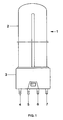
Figur 1- zeigt in Seitenansicht eine erfindungsgemäße Niederdruckentladungslampe mit einem Sockel
Figur 2- zeigt in Seitenansicht ein teilweise geschnittenes
Entladungsgefäß einer Niederdruckentladungslampe
gemäß
Figur 1, Figur 3- zeigt einen Schnitt durch das Entladungsgefäß
gemäß
Figur 2 an der Stelle I, I'.
- Figure 1
- shows a side view of a low-pressure discharge lamp according to the invention with a base
- Figure 2
- shows a side view of a partially sectioned discharge vessel of a low-pressure discharge lamp according to FIG. 1,
- Figure 3
- shows a section through the discharge vessel according to Figure 2 at point I, I '.
In Figur 1 ist eine kompakte Niederdruckentladungslampe
1 mit einer Leistungsaufnahme von 18 W aufgezeigt,
die sich aus einem verkürzt dargestellten
Entladungsgefäß 2 und einem Sockel 3 vom Typ 2 G 11
zusammensetzt. Der Sockel weist vier Anschlußstifte
4 bis 7 auf, die über die Fassungskontakte mit dem
Vorschaltgerät verbunden werden.In Figure 1 is a compact low
Figur 2 zeigt in verkürzter Darstellung das Entladungsgefäß
2 der Lampe aus Figur 1. Es weist eine
Länge von 19,6 cm auf und setzt sich aus zwei geraden
Längsrohrabschnitten 8, 9 mit kreisförmigem
Querschnitt und eine: 180°-Biegung 10 zusammen. In
die freien Enden der beiden Längsrohrabschnitte 8, 9
mit einem inneren Durchmesser von 15,5 mm und einer
Wanddicke von 1 mm sind jeweils zwei Stromzuführungen
11, 12 bzw. 13, 14 eingequetscht. Diese Stromzuführungen
11, 12 bzw. 13, 14 tragen Elektrodenwendeln
15, 16 und werden mittels einer Glasperle 17, 18
im Innern des Gefäßes zusammengehalten. In eine 20
der beiden Quetschungen 19, 20 der Längsrohrabschnitte
8, 9 ist außerdem ein Pumpröhrchen 21 eingequetscht,
das nach der Füllung des Entladungsgefäßes 2
abgeschmolzen wurde. Auf der Innenwand des Entladungsgefäßes
2 ist eine Leuchtstoffbeschichtung 22 aufgebracht.FIG. 2 shows the discharge vessel in a shortened
Die 180°-Biegung 10 weist einen großen Außenradius
auf und verengt sich zur Scheitellinie I, I' hin. Der
Innendurchmesser der Biegung besitzt am Übergang zu
den Längsrohrabschnitten 8, 9 einen kreisförmigen
Innenquerschnitt von 15,5 mm Durchmesser und verengt
sich am Scheitel, wie aus Figur 3 ersichtlich, zu
einer Ellipse mit einer großen Achse D von 15,5 mm
und einer kleinen Achse d von 10 mm. Die kleine Achse
d verläuft dabei in Richtung der Längsrohrabschnitte
8, 9. Die Wand des Entladungsgefäßes ist an der äusseren
Mantelfläche der 180°-Biegung 10 verdickt. Sie
weist an dem dem Sockel zugewandten Teil der Ellipse
eine Dicke von 1 mm auf und nimmt auf dem dem Sockel
abgewandten Teil der Ellipse bis auf 2 mm an der äusseren
Mantellinie zu.The 180 °
Die Erfindung ist nicht auf eine Niederdruckentladungslampe mit einem Entladungsgefäß aus lediglich einem U-förmigen Glasrohr beschränkt. Das Entladungsgefäß kann auch aus mehreren U-förmigen Glasrohren bestehen, wie dies z.B. in der EP-PS 0 143 419 gezeigt wird. In diesem Fall muß die 180°-Biegung jedes U-förmigen Glasrohres die erfindungsgemäßen Merkmale aufweisen, damit mit der Lampe bei niedrigen Umgebungstemperaturen eine optimale Lichtausbeute erzielt wird.The invention is not based on a low pressure discharge lamp with a discharge vessel only restricted to a U-shaped glass tube. The discharge vessel can also consist of several U-shaped glass tubes exist, such as shown in EP-PS 0 143 419 becomes. In this case, the 180 ° bend must each U-shaped glass tube the features of the invention with the lamp at low ambient temperatures optimal light output achieved becomes.
Claims (2)
- Low-pressure discharge lamp (1) having a wound discharge vessel (2) assembled from one or more glass tubes bent in a U-shaped fashion, two electrodes (15, 16) sealed tightly at the ends of the discharge vessel (2), a filling made from mercury and at least one noble gas, as well as a fluorescent coating (22) on the inner wall of the discharge vessel (2), the tube or tubes bent in a U-shaped fashion comprising in each case two longitudinal tube sections (8, 9) which extend in parallel, are sealed at their free ends and have a circular inner cross-section and a 180° bend (10), and in the case of a plurality of glass tubes bent in a U-shaped fashion said tubes are arranged parallel next to one another and are connected to one another via a transverse fusion near the free ends of the longitudinal tube sections (8, 9), characterized in that the inside diameter of the 180° bend (10) decreases from the transition of the longitudinal tube section (8, 9) to the apex (I, I') of the tube bent in a U-shaped fashion, and has at the apex (I, I') an essentially elliptical inner cross-section, the ratio of the minor axis d to the major axis D satisfying the equation
- Low-pressure discharge lamp (1) according to Claim 1, characterized in that in the region of the outer lateral surface of the 180° bend (10) the wall of the glass tube or tubes bent in a U-shaped fashion has a thickness s which satisfies the inequality
Applications Claiming Priority (2)
| Application Number | Priority Date | Filing Date | Title |
|---|---|---|---|
| DE4215674A DE4215674A1 (en) | 1992-05-13 | 1992-05-13 | Low pressure discharge lamp |
| DE4215674 | 1992-05-13 |
Publications (2)
| Publication Number | Publication Date |
|---|---|
| EP0569814A1 EP0569814A1 (en) | 1993-11-18 |
| EP0569814B1 true EP0569814B1 (en) | 1998-03-18 |
Family
ID=6458709
Family Applications (1)
| Application Number | Title | Priority Date | Filing Date |
|---|---|---|---|
| EP93107162A Expired - Lifetime EP0569814B1 (en) | 1992-05-13 | 1993-05-03 | Low pressure discharge tube |
Country Status (7)
| Country | Link |
|---|---|
| EP (1) | EP0569814B1 (en) |
| JP (1) | JPH0620650A (en) |
| KR (1) | KR930024080A (en) |
| CN (1) | CN1081020A (en) |
| CA (1) | CA2096073C (en) |
| DE (2) | DE4215674A1 (en) |
| HU (1) | HU213967B (en) |
Families Citing this family (8)
| Publication number | Priority date | Publication date | Assignee | Title |
|---|---|---|---|---|
| JP2577967B2 (en) * | 1988-08-05 | 1997-02-05 | 日立建機株式会社 | Engine remote control |
| DE19515380A1 (en) * | 1995-05-02 | 1996-11-07 | Walter Holzer | Power saving gas-discharge lamp |
| DE19517993A1 (en) * | 1995-05-18 | 1996-11-21 | Walter Holzer | Electrical gas discharge bulb |
| DE19601733A1 (en) * | 1996-01-19 | 1997-07-24 | Holzer Walter Prof Dr H C Ing | Gas discharge vessel with cold spots e.g. for low pressure gas discharge lamp |
| DE29602733U1 (en) * | 1996-02-20 | 1996-04-04 | Holzer Walter Prof Dr H C Ing | Energy-saving lamp with coiled gas discharge vessel and separable ballast |
| HU218642B (en) * | 1996-12-30 | 2000-10-28 | General Electric Co | Single ended discharge lamp |
| EP1047110B1 (en) * | 1999-04-22 | 2010-03-03 | Panasonic Corporation | Fluorescent lamp and method for manufacturing the fluorescent lamp |
| DE60043132D1 (en) | 1999-05-19 | 2009-11-26 | Panasonic Corp | U-shaped low-pressure mercury vapor discharge lamp and manufacturing method for such a lamp |
Citations (2)
| Publication number | Priority date | Publication date | Assignee | Title |
|---|---|---|---|---|
| EP0061758A2 (en) * | 1981-03-31 | 1982-10-06 | Patent-Treuhand-Gesellschaft für elektrische Glühlampen mbH | Low-pressure mercury vapour lamps and method for their manufacture |
| EP0572835A1 (en) * | 1992-05-26 | 1993-12-08 | Patent-Treuhand-Gesellschaft für elektrische Glühlampen mbH | Low-pressure mercury vapor discharge lamp |
Family Cites Families (4)
| Publication number | Priority date | Publication date | Assignee | Title |
|---|---|---|---|---|
| JPH0746598B2 (en) * | 1986-05-29 | 1995-05-17 | 東芝ライテック株式会社 | Fluorescent lamp |
| SE8800747D0 (en) * | 1988-03-02 | 1988-03-02 | Lumalampan Ab | Low pressure gas discharge lamp |
| JPH083997B2 (en) * | 1988-12-12 | 1996-01-17 | 東芝ライテック株式会社 | Low pressure mercury vapor discharge lamp |
| DE4012588C2 (en) * | 1990-04-20 | 1994-02-17 | Norka Norddeutsche Kunststoff | Luminaire for low ambient temperatures |
-
1992
- 1992-05-13 DE DE4215674A patent/DE4215674A1/en not_active Withdrawn
-
1993
- 1993-04-30 JP JP5128423A patent/JPH0620650A/en active Pending
- 1993-05-03 DE DE59308264T patent/DE59308264D1/en not_active Expired - Fee Related
- 1993-05-03 EP EP93107162A patent/EP0569814B1/en not_active Expired - Lifetime
- 1993-05-06 KR KR1019930007715A patent/KR930024080A/en not_active Application Discontinuation
- 1993-05-10 CN CN93105662A patent/CN1081020A/en active Pending
- 1993-05-12 HU HU9301381A patent/HU213967B/en not_active IP Right Cessation
- 1993-05-12 CA CA002096073A patent/CA2096073C/en not_active Expired - Fee Related
Patent Citations (2)
| Publication number | Priority date | Publication date | Assignee | Title |
|---|---|---|---|---|
| EP0061758A2 (en) * | 1981-03-31 | 1982-10-06 | Patent-Treuhand-Gesellschaft für elektrische Glühlampen mbH | Low-pressure mercury vapour lamps and method for their manufacture |
| EP0572835A1 (en) * | 1992-05-26 | 1993-12-08 | Patent-Treuhand-Gesellschaft für elektrische Glühlampen mbH | Low-pressure mercury vapor discharge lamp |
Also Published As
| Publication number | Publication date |
|---|---|
| HU213967B (en) | 1997-11-28 |
| JPH0620650A (en) | 1994-01-28 |
| KR930024080A (en) | 1993-12-21 |
| CN1081020A (en) | 1994-01-19 |
| CA2096073A1 (en) | 1993-11-14 |
| DE59308264D1 (en) | 1998-04-23 |
| HUT64158A (en) | 1993-11-29 |
| DE4215674A1 (en) | 1993-11-18 |
| CA2096073C (en) | 2002-07-16 |
| HU9301381D0 (en) | 1993-09-28 |
| EP0569814A1 (en) | 1993-11-18 |
Similar Documents
| Publication | Publication Date | Title |
|---|---|---|
| DE3011382A1 (en) | LOW PRESSURE GAS DISCHARGE LAMP | |
| DE3027536C2 (en) | ||
| EP0569814B1 (en) | Low pressure discharge tube | |
| EP0453652B1 (en) | High pressure discharge lamp | |
| EP0446460B1 (en) | Halogen incandescent lamp having a single pinch | |
| DE3632810A1 (en) | FLUORESCENT LAMP DEVICE | |
| EP0572835B1 (en) | Low-pressure mercury vapor discharge lamp | |
| DE69530564T2 (en) | Circular fluorescent lamp | |
| EP0034113B1 (en) | Electric discharge lamp | |
| DE4229894B4 (en) | Coupling device for feeding microwave energy to excite electrodeless lamps | |
| DD253510A5 (en) | LOW PRESSURE MERCURY VAPOR DISCHARGE LAMP | |
| DE2118828B2 (en) | High pressure sodium vapor discharge lamp | |
| EP0894336B1 (en) | Incandescent lamp with reflection coating | |
| DE19755680A1 (en) | Low power consumption gas discharge light bulb | |
| EP0987737B1 (en) | Fluorescent lamp | |
| DE19726919C2 (en) | Bulb shaped fluorescent lamp | |
| DE3510156A1 (en) | LOW PRESSURE MERCURY STEAM DISCHARGE LAMP | |
| EP1659617A1 (en) | Light source | |
| EP0446461B1 (en) | Halogen incandescent lamp having a single pinch | |
| DE19613358C1 (en) | Optical spotlight | |
| DE60019201T2 (en) | Tubular glass vessel comprising incandescent lamp with a longitudinally incorporated filament | |
| EP1709668B1 (en) | Low-pressure discharge lamp | |
| DE3613881A1 (en) | LOW PRESSURE MERCURY STEAM DISCHARGE LAMP | |
| DE1539527C (en) | High pressure mercury lamp of small power and small size | |
| DE8227130U1 (en) | GAS AND / OR VAPOR DISCHARGE LAMP WITH A U-SHAPED DISCHARGE TUBE |
Legal Events
| Date | Code | Title | Description |
|---|---|---|---|
| PUAI | Public reference made under article 153(3) epc to a published international application that has entered the european phase |
Free format text: ORIGINAL CODE: 0009012 |
|
| AK | Designated contracting states |
Kind code of ref document: A1 Designated state(s): DE FR GB IT SE |
|
| 17P | Request for examination filed |
Effective date: 19931216 |
|
| 17Q | First examination report despatched |
Effective date: 19950320 |
|
| GRAG | Despatch of communication of intention to grant |
Free format text: ORIGINAL CODE: EPIDOS AGRA |
|
| GRAG | Despatch of communication of intention to grant |
Free format text: ORIGINAL CODE: EPIDOS AGRA |
|
| GRAH | Despatch of communication of intention to grant a patent |
Free format text: ORIGINAL CODE: EPIDOS IGRA |
|
| GRAH | Despatch of communication of intention to grant a patent |
Free format text: ORIGINAL CODE: EPIDOS IGRA |
|
| GRAA | (expected) grant |
Free format text: ORIGINAL CODE: 0009210 |
|
| AK | Designated contracting states |
Kind code of ref document: B1 Designated state(s): DE FR GB IT SE |
|
| REF | Corresponds to: |
Ref document number: 59308264 Country of ref document: DE Date of ref document: 19980423 |
|
| ITF | It: translation for a ep patent filed |
Owner name: STUDIO JAUMANN P. & C. S.N.C. |
|
| ET | Fr: translation filed | ||
| GBT | Gb: translation of ep patent filed (gb section 77(6)(a)/1977) |
Effective date: 19980520 |
|
| PLBE | No opposition filed within time limit |
Free format text: ORIGINAL CODE: 0009261 |
|
| STAA | Information on the status of an ep patent application or granted ep patent |
Free format text: STATUS: NO OPPOSITION FILED WITHIN TIME LIMIT |
|
| 26N | No opposition filed | ||
| PGFP | Annual fee paid to national office [announced via postgrant information from national office to epo] |
Ref country code: GB Payment date: 19990510 Year of fee payment: 7 |
|
| PGFP | Annual fee paid to national office [announced via postgrant information from national office to epo] |
Ref country code: FR Payment date: 19990520 Year of fee payment: 7 |
|
| PGFP | Annual fee paid to national office [announced via postgrant information from national office to epo] |
Ref country code: SE Payment date: 19990527 Year of fee payment: 7 |
|
| PGFP | Annual fee paid to national office [announced via postgrant information from national office to epo] |
Ref country code: DE Payment date: 19990720 Year of fee payment: 7 |
|
| PG25 | Lapsed in a contracting state [announced via postgrant information from national office to epo] |
Ref country code: GB Free format text: LAPSE BECAUSE OF NON-PAYMENT OF DUE FEES Effective date: 20000503 |
|
| PG25 | Lapsed in a contracting state [announced via postgrant information from national office to epo] |
Ref country code: SE Free format text: LAPSE BECAUSE OF NON-PAYMENT OF DUE FEES Effective date: 20000504 |
|
| GBPC | Gb: european patent ceased through non-payment of renewal fee |
Effective date: 20000503 |
|
| EUG | Se: european patent has lapsed |
Ref document number: 93107162.5 |
|
| PG25 | Lapsed in a contracting state [announced via postgrant information from national office to epo] |
Ref country code: FR Free format text: LAPSE BECAUSE OF NON-PAYMENT OF DUE FEES Effective date: 20010131 |
|
| PG25 | Lapsed in a contracting state [announced via postgrant information from national office to epo] |
Ref country code: DE Free format text: LAPSE BECAUSE OF NON-PAYMENT OF DUE FEES Effective date: 20010301 |
|
| REG | Reference to a national code |
Ref country code: FR Ref legal event code: ST |
|
| PG25 | Lapsed in a contracting state [announced via postgrant information from national office to epo] |
Ref country code: IT Free format text: LAPSE BECAUSE OF NON-PAYMENT OF DUE FEES Effective date: 20050503 |