EP0569710A1 - Safety vehicle wheel with a spare wheel inside its tire - Google Patents
Safety vehicle wheel with a spare wheel inside its tire Download PDFInfo
- Publication number
- EP0569710A1 EP0569710A1 EP93105889A EP93105889A EP0569710A1 EP 0569710 A1 EP0569710 A1 EP 0569710A1 EP 93105889 A EP93105889 A EP 93105889A EP 93105889 A EP93105889 A EP 93105889A EP 0569710 A1 EP0569710 A1 EP 0569710A1
- Authority
- EP
- European Patent Office
- Prior art keywords
- wheel
- tire
- air
- rim
- spare
- Prior art date
- Legal status (The legal status is an assumption and is not a legal conclusion. Google has not performed a legal analysis and makes no representation as to the accuracy of the status listed.)
- Granted
Links
- 238000001816 cooling Methods 0.000 claims abstract description 48
- 229920001971 elastomer Polymers 0.000 claims description 35
- 239000005060 rubber Substances 0.000 claims description 35
- 230000007812 deficiency Effects 0.000 claims description 23
- 239000002184 metal Substances 0.000 claims description 23
- 229910052751 metal Inorganic materials 0.000 claims description 23
- 238000010009 beating Methods 0.000 claims description 22
- 238000000151 deposition Methods 0.000 claims description 18
- 229920000742 Cotton Polymers 0.000 claims description 12
- 230000015572 biosynthetic process Effects 0.000 claims description 11
- 238000004519 manufacturing process Methods 0.000 claims description 9
- XLYOFNOQVPJJNP-UHFFFAOYSA-N water Substances O XLYOFNOQVPJJNP-UHFFFAOYSA-N 0.000 claims description 5
- 238000002844 melting Methods 0.000 claims description 2
- 230000008018 melting Effects 0.000 claims description 2
- 241000711981 Sais Species 0.000 claims 1
- 238000010276 construction Methods 0.000 abstract description 4
- 241000219146 Gossypium Species 0.000 description 10
- 239000004033 plastic Substances 0.000 description 10
- 230000007547 defect Effects 0.000 description 3
- JEIPFZHSYJVQDO-UHFFFAOYSA-N iron(III) oxide Inorganic materials O=[Fe]O[Fe]=O JEIPFZHSYJVQDO-UHFFFAOYSA-N 0.000 description 2
- 239000000463 material Substances 0.000 description 2
- 230000000717 retained effect Effects 0.000 description 2
- 241000272525 Anas platyrhynchos Species 0.000 description 1
- RYGMFSIKBFXOCR-UHFFFAOYSA-N Copper Chemical compound [Cu] RYGMFSIKBFXOCR-UHFFFAOYSA-N 0.000 description 1
- 244000182067 Fraxinus ornus Species 0.000 description 1
- 229910052802 copper Inorganic materials 0.000 description 1
- 239000010949 copper Substances 0.000 description 1
- 238000007373 indentation Methods 0.000 description 1
- 230000002093 peripheral effect Effects 0.000 description 1
- 239000012466 permeate Substances 0.000 description 1
- 238000005086 pumping Methods 0.000 description 1
- 239000011800 void material Substances 0.000 description 1
Images


Classifications
-
- B—PERFORMING OPERATIONS; TRANSPORTING
- B60—VEHICLES IN GENERAL
- B60C—VEHICLE TYRES; TYRE INFLATION; TYRE CHANGING; CONNECTING VALVES TO INFLATABLE ELASTIC BODIES IN GENERAL; DEVICES OR ARRANGEMENTS RELATED TO TYRES
- B60C17/00—Tyres characterised by means enabling restricted operation in damaged or deflated condition; Accessories therefor
- B60C17/04—Tyres characterised by means enabling restricted operation in damaged or deflated condition; Accessories therefor utilising additional non-inflatable supports which become load-supporting in emergency
- B60C17/06—Tyres characterised by means enabling restricted operation in damaged or deflated condition; Accessories therefor utilising additional non-inflatable supports which become load-supporting in emergency resilient
-
- B—PERFORMING OPERATIONS; TRANSPORTING
- B60—VEHICLES IN GENERAL
- B60C—VEHICLE TYRES; TYRE INFLATION; TYRE CHANGING; CONNECTING VALVES TO INFLATABLE ELASTIC BODIES IN GENERAL; DEVICES OR ARRANGEMENTS RELATED TO TYRES
- B60C17/00—Tyres characterised by means enabling restricted operation in damaged or deflated condition; Accessories therefor
- B60C17/04—Tyres characterised by means enabling restricted operation in damaged or deflated condition; Accessories therefor utilising additional non-inflatable supports which become load-supporting in emergency
- B60C17/041—Tyres characterised by means enabling restricted operation in damaged or deflated condition; Accessories therefor utilising additional non-inflatable supports which become load-supporting in emergency characterised by coupling or locking means between rim and support
- B60C17/042—Tyres characterised by means enabling restricted operation in damaged or deflated condition; Accessories therefor utilising additional non-inflatable supports which become load-supporting in emergency characterised by coupling or locking means between rim and support preventing sliding or rotation between support and rim
-
- B—PERFORMING OPERATIONS; TRANSPORTING
- B60—VEHICLES IN GENERAL
- B60C—VEHICLE TYRES; TYRE INFLATION; TYRE CHANGING; CONNECTING VALVES TO INFLATABLE ELASTIC BODIES IN GENERAL; DEVICES OR ARRANGEMENTS RELATED TO TYRES
- B60C19/00—Tyre parts or constructions not otherwise provided for
- B60C2019/006—Warning devices, e.g. devices generating noise due to flat or worn tyres
Definitions
- the invention relates to the construction of vehicle-wheel, particularly to, a safety vehicle-wheel with a spare wheel which is need not to pump air.
- the safety vehicle-wheel can immediately re-support a vehicle to be driven continuously and especially can avoid an accident when blowout or air leakage of a tire is happened.
- the invention is relates to the construction of vehicle-wheel, particularly to, a safety vehicle-wheel with a spare wheel which need not to pump air.
- the safety vehicle wheel can immediately re-support a vehicle to be drived continuously and especially avoid an accident when blowout or air leakage of a tire is happened.
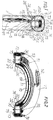
- the safety vehicle-wheel comprises a combinative wheel-rim which is formed by a seperable way to connect one plate member which has one flange the same as the flange of vehicle-wheel with a annular member which also has one flange the same as the flange of vehicle-wheel and a inward flange respectively on its two sides , a spare wheel which is need not pump air and is connected between the plate member and the annular member, a tire, a cooling device etc..
- the outer circumference of the spare wheel is kept at a proper distance with the inside circumference of the tire.
- the objects of the invention is not only to make vehicle be drived continuously but also to avoid an accident when blowout or air leakage of a tire is happened. Besides, it also provides a solution for the prior art's two defects.
- the invention comprising a combinative wheel-rim , two hollow half ring of main hard ring of formation the spare wheel, a tire, one pair of washers (gaskets), one pair of plugs, restrictor rings, a cooling device and bolts etc..
- the combinative wheel-rim is formed by a separable way to connect (merge) a plate member 1 which has one flange 2 the same as the flange of vehicle-wheel with a annular member 5 which also has one flange 3 the same as the flange of the vehicle-wheel and inward flange 4 respectively on its two sides to install the tire 5A fit.
- the bottom of the plate member has one set of fixed bolts 6 on nearby the periphery of the bottom.
- the inward flange 4 of the annular member has one set of holes 7 which can symmetry with the bolts 6.
- the two hollow half rings are respectively formed include by connecting a half annular trough 8 which is hasing three sides at least and its mouth is on side with a half wall ring 9 which is able to support two sides of trough of the half annular trough to compose a hollow half ring (a half spare wheel please see fig.2).
- the inner side ( inner circumference ) of each half annular trough hasing a inward flange 10 can provide be clamped between the bottom of the plate member 1 and the inward flange 4 of the annular member 5 so as to fix each half spare wheel and make the two half spare wheels into one spare wheel inside the tire.
- Each inward flange 10 has one set of holes 11 can let the bolts 6 through so as to each inward flange be connected between the plate member 1 and the annular member 5.
- the means of connecting the half annular trough 8 with the half wall ring 9,include has several pair of symmetrical holes on the half annular trough and the half wall ring can let bolts 12 through and to connect the half annular tought 8 with the half wall ring 9.
- the half wall ring has several convex portions or has wide convex portion slightly 13 of only slight edge be kept on periphery so as to supporting two side of trough of the half annulr trough by the side of upper and dowm of each several convex portions or the wide convex portion so that able to reinforce supporting force of the spare wheel.
- the half wall ring is thicknesser than the half annular trough so as to make the spare wheel firmnesser.
- the pair of washers ( gaskets ) 14,15 are made by a article of able anti-corrode and heat-resisting and of having a resilience as a rubber. Each washer has one set holes can symmetry with the holes 11.
- the pair of washers are respectively connected between the inward flange 10 and the plate member 1 as well as the inward flange 10 and the inward flange 4 of the annular member 5 to make the plate member and the inward flange 10 as well as the annular member 5 be connected closely so as to prevent air leakage of the tire.
- the two ends of the inward flange of each half annular trough have a radial gap 16,17 respectively, so as to form a hole (for example Fig.5 No.18,19) between the connected end and end of the inward flange of each half annular trough, when the two hlaf spare wheel are connected into one spare wheel.
- the pair of plugs are used to tuck each hole of the gaps to form as above respectively to make the end and end of each inward flange to be connected closely to prevent air leakage of the tire.
- the material of each plug is the same as the pair of washers.
- each plug as a washer-shape 20, besides , the hollow portion of the each plug has a hard plug 21 being tucked into to make each plug 20 to be distended after each plug 20 being tucked into each hole of gaps to form as above for each plug 20 being tucked tightly.
- a connecting-pieces for example 22, 23 ) is used to connect each half spare wheel into one spare wheel for fixing each half spare wheel in the tire conveniently and enable the spare wheel firmnesser.
- the connecting-pieces are one set by two and respectively is over on two side of the end of be connected of each half hollow ring then be bolted together by two bolts 23A, 23B.
- the two bolts 23A, 23B are be bolted on wherein one of the two connecting-pieces at beforehand, besides, wherein one of the two bolts is through two symmetrical holes of one end of each half spare wheel ( each half hollow ring ) at beforehand and be fixed on each spare whell by tightly through the symmetrical holes at beforehand so as to the connecting of the connecting-pieces conveniently.
- the restrictor rings have two 24,25 and each is to withstand and restricting the rim 26,27 of the tire to remove toward the inside of the tire when the air of the tire is deficiency.
- the restrictor ring 24 is encircles on the circumference of the annular portion 28 of between the flange and the bottom of the plate member and two ends of one side of the restrictor ring 24 are fixed on the side 29, 30 of two ends of the half wall ring at least by the convex portion 31,32 of two ends of the restrictor ring 24 to respectively clamp in the gap of two ends of the half wall ring.
- the restrictor ring 25 encircles on the circumference of the annular portion 33 of between the flange and the inward flange of the annular member and two ends of one side of the restrictor ring 25 are fixed on the side 34,35 of two ends of the half annular trough at least by the convex portion 36,37 of two end of the The restrictor ring 25 to respectively clamp in the gap of two ends of the half annular trough.
- the formation of each restrictor ring includes by a ring or half ring.
- Each restrictor ring will not only withstand and restrict each rim of the tire to remove, but also will closely contact with each rim of the tire, the above close contact is closer than the contact of the flange of the conventional wheel-rim with the rim of the conventional tire ,therefore, not air leakage than the contact of the conventional as above ,especially the flange of the wheel-rim happens a concave when a vehicle is drived and the flange of its wheel-rim is bumping a hole on road or bumping other hard object on the road ,yet,this is impossible to avoiding a wheel-rim bumping the hole on the road,because many holes will happen on a road , namely when raining at long time or repairing roads.
- the replace as above includes the two restrictor ring 24,25 are manufactured become one ring ( please see fig.11 No.25A ) and width is increased ( namely to increase the width of without the spare wheel ) and then encircle on the circumference of the annular portion 28, 33 of the plate member and the annular member 5.
- This invention also belongs to me if the combinative wheel-rim is used as above to replace the conventional wheel-rim.
- the formation of the ring 25A includes to be manufactured into two half rings and then to be connected to form one ring.
- the two restrictor ring further include to be connected ( merge ) with a rubber ring 25B,25C respectively to make closely contact furthermore with the rim of the conventional tire so as to not air leakage furthermore and avoiding to use the spare wheel when the flange of the combinative wheel-rim is bumping the hole on the road.
- the cooling device is to make the inner temperature of the tire reduced when blowout generates at press and loose of the portion contact of the tire contact with the road surface and generates contact of the spare wheel with the inside of the tire.
- the cooling device comprises two half annular containers of cooling articles, a cooling articles (for example water ) ,the exits of the cooling articles, a plugs is tucked the exits, a design anable each plug secede from each exit of the cooling articles when blowout generates contact of the spare wheel with the inside of the tire, a device of retrieveal the cooling articles etc..
- Each container 38 is installed in the hollow portion of each hollow half ring (each half spare wheel) and is be fixed via each screw 12 through a hollow supporting pillar 39 of the inner of each the container and be bolted.
- Each container is formed includes by a flat half annular cover 40 to covering on a half annular trough 41 with four sides.
- the upper portion of the four sides of the half annular trough 41 respectively has a inner step 42, 43 which is provided the annular cover 40 to covering into.
- the annular cover 40 has holes 44 with inner 35 step 45 which can symmetrize with each hollow portion 46 of each support pillar 39 to provide for each bolt 12 through to connect the annular cover 40 with the half annular trough 41 so as to form each the container.
- the upper end of each support pillar has washer (gasket) 47 able to prevent the cooling articles permeate into each hollow portion of each support pillar.
- Each container has a transparent device on a proper located so as to see the quantity of the cooling articles.
- the exits of the cooling articles is formed by the holes on the outer circumference of each the container and each exit is tucked by a plug 48.
- the material of each plug 48 is the same as the pair of washers 14,15.
- Each plug 48 is tightly jostled into each hole on the circumference of each container,therefore is tightly fixed on each container , besides, each plug 48 with flange 49 on one end for making each plug not falling the outside of each container.
- each plug secede includes that each plug is properly extending the outside of each container and that is properly extending the hole on the circumference of half annular trough 8 and that has a hard object 50 in the hollow portion of each plug so that will be jostled via the inside of the tire and automatic fall inward the inside of each the container and let the cooling articles flow to reduce the inner temperature of the tire when blowout generates contact of the spare wheel with the inside of tire.
- each each exit is a tapped hole and each plug is first tuck the hollow portion of a hollow bolt then to tuck each exit via the bolt screwed into the each tapped hole .
- the device of retrieval the cooling articles is by installing articles which is able to absorb the water (for example cottons or cotton goods 51 or a device 52 able to dip the cooling articles such as arc-shaped small rubber troughs ) on two sides of the each hollow half ring so as to absorb or dip the cooling articles of flow from the exits of the cooling articles to reducing the cooling articles flow to the outside of the tire when blowout.
- the articles which is able to absord the water is covered by a web 53 or a cover with small holes.
- each container of cooling articles respectively has several holes 54 can let the cooling articles flow to two sides of each hollow half ring ( each hollow half spare wheel ) to make the spare wheel further able to reducing inner heat of the tire ( each hollow half ring also can disperse the heat of wheel-rim ) when the vehicle be drived and tire generate heat.
- each of the several holes 54 is respectively be covered by a thin stainless metal cover 55 so that can prevent two sides of the hollow half ring rust.
- the thin stainless metal is able to heat conduction from the side the hollow half ring, because metal is able to heat conduction and each stainless metal cover is contact with the the inside of the hollow half ring. For prevent the cooling articles flow to the outside of each stainless metal cover, therefore, has a gasket between each stainless metal cover and the each hole.
- the annular portion 33 of between the flange and the inward flange of the annular member has a step 56,besides, the circumference of the annular portion 28 of the plate member is bigger than the circumference 57 of without the step of the annular portion of the annular member,so that can into a annular concave portion between the step and the bigger so as to let the inner circumference of the spare wheel inlay into and be tightly clamped via the step and the bigger to make the spare wheel very stoutly be installed when the plate member and the annular member be bolted together via the bolt 6.
- the inner circumference 58 of each half annular trough is against the outer circumference 57 of without the step of the annular portion,therefore, the spare wheel is very stoutly installed.
- the half annular trough 8 can need not having the inward flange 10 and only a half annular trough 59, that is the formation of the inward flange 10 can be replaced by the inward width 60 of the half wall ring,the inward width 60 is over inner side ( inner circumference ) of the half annular trough.
- each half spare wheel includes by a half annular trough 61 which is trough mouth toward its inner side ( inner circumference ) and has three sides at least as well as the width 62 of one side of two sides of trough is widther than other side so as to can replace the inward flange 10.
- the metal sheet of be used to manufacturing the plate member is first excisced some portion by lathe and become a annular step 63 , the some portion is on one side of the metal sheet and the some portion is from the circumference of the metal sheet to the portion of the metal sheet will be manufactured into the bottom of the plate member before the metal sheet is used to manufacturing the plate member.
- the bottom of the plate membere has two keys 63B at least respectively be fixed on the peripheral sides of the bottom and are symmetry which is for the vehicle-wheel balancing when turning,the two keys are not only respectively through two holes of the inward flange 10 but also through two holes of the inward flange 4 of the annular member so as to strengthen the combinative wheel-rim to bear the force twisting of axle.
- each support pillar be inserted a short pipe 64 so that can prevent a indentation on the half annular trough 8 and the half wall ring 9 is happened 9 when the half annular trough and the half wall ring are connected by each bolt 12.
- angles 65, 66 of respectively formed via the annular portion 28 and bottom of the plate member as well as via the annular portion 33 and inward flange 4 of the annular member can make the safety vehicle-wheel and the spare wheel enough to support the weight of a vehicle and can make the spare wheel very firmness.
- the bottom of the plate member has a set of square holes 67 or a holes with angles can provide for the set of bolts 6 to be through,besides, each of the set of bolts has a square portion 68 or a portion with angles on one end which locates near the head of the each bolt.
- Each square hole or each hole with angles and each square portion or each portion with angles is for prevent the each bolt being turned when each of the set of nuts 69 is become tight.
- each half annular rubber 70 of be encircled on the circumference of the spare wheel is be fixed by the flange 71,72 on two side of each half annular rubber respectively be inlay into the annular groove 73,74 of a half ring.
- Each half ring is fixed by the edge 75 of each half ring being respectively fixed via several bolts 76 on the two sides of the hollow half ring so each half ring is stout fixed, because each of the several bolts 76 is respectively screwed into each tapped hole 76A of two sides of each container.
- the outer circumference and two sides of the each half annular rubber are be packed by an cotton goods 77 and have cottons 77A between the cotton goods and the annular rubber so as to absorb the cooling articles of flow from the exits of the cooling articles to reducing the cooling articles flow to the outside of the tire when the tire is blowout.
- the cottons include to be replaced by the manufactured capillary one side of the cotton goods.
- the two sides of the cotton goods 77 are respectively fixed on the two sides of the each hollow half ring by the bolts 12.
- Each half annular rubber and the cotton goods with holes 78 can provide for each plug 48 through.
- Another preferred embodiment of the of washer 14,15 includes to be replaced by two half annular washers (gaskets) with half annular groove 79 on its circumference ,if so, the gap 16,17 and the plug 20,21 can be needless,because, on the two ends of each half annular washer are respectively has a portion 80 of all thickness which is located the angle of near the inner circumference of each half annular washer, besides, the portion of the all thickness of each half annular washer is lateral so extending slightly , which is will mutual to press tightly that not space on between 81 the connected end and end of the inward flange 10 of each half annular trough. Two ends of each inward flange 10 respectively has be excised one angle 82 which is can match with the portion of the all thickness .
- Another preferred embodiment of the spare wheel include the inward flange 10 be cancel and to make the spare wheel is only a hollow ring then be clamping between the bottom of plate member and the step 56 of the annular member so as to reducing the weight of the spare wheel.
- the periphery of the bottom of the plate member has several holes of without pierce through the bottom, besides , each hole is be seted into a key 56A so as to through each hole of can symmetry with the key 56A of the hollow rings so that can prevent the spare wheel ( the hollow rings ) void turning when tread .
- Another preferred embodiment of the spare wheel includes the two half hollow ring respectively is has a half annular wall or supports 86 inside its hollow portion, so that can to supporting two sides of trough of each half annular trough so as to strengthen the supporting force of the spare wheel then to supporting the vehicle.
- Two side of the half annular wall or supports is respectively be retained and steady by a U-shaped supports 87,88 and a flat supports 88A ,88B which each is has gap of can match with each of the gaps of the edge of two sides of the half annular wall.
- the independent one side of each U-shaped support has hole 89,90 let each bolt 12 through.
- each container 38 includes be replaced by several short containers 91, so as to needn't use a long containers the same as the long of the container 38 and can avoiding need changing long container if wherein one long container is breakage after blowout and the spare wheel is tread some times already.
- the plug 48 includes be replace by a hollow rubber plug 92 and which be covered by a plastic cover 93 which is can automatic melt at proper heat which is after bolwout and the spare wheel is tread some time and generate heat so as to let the cooling articles flow.
- Beneath the plastic cover has a rubber cover 94 covering on the exit of the hollow rubber plug and is be compressing via the plastic cover ,therefore, the rubber cover 94 not only enable the cooling articles not contact with the plastic cover but also enable the plastic cover quickly breach when the plastic cover melt.
- the plastic cover is a trough-shaped and is insert the annular groove of the thick portion of the circumference of the hollow rubber plug via the circumference 95 of the plastic cover.
- the circumference of the plastic cover is biger than the hole 96 on the circumference of the half annular trough 8 so that not falling to the outside of the spare wheel ,besides, one end of the hollow rubber plug is biger than the step 97 which is inside the hole of the short container so that not falling inside each short container.
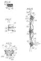
- the safety vehicle-wheel of the invention further includes a automatic replenish air device, the automatic replenish air device able to automatic replenish air into the inside of the tire when the tire is deficiency air.
- the automatic replenish air device includes a depositing member of depositing a spare air ,the depositing member is be formed includes by a annular trough 98 which is trough-mouth on side and be inlayed into the inside of the plate member 1,the trough-mouth 99 of the annular trough is toward the bottom of the inside of the plate member, the edge of two side of the annular trough respectively be inlayed into the groove of an annular gasket 100, 100A, the annular trough has a valve 101 can provide for pump air into its inside, a air exit 102 which is output air into the tire etc.
- the bottom of annular trough has seveaal concave portions 103 respectively can provide for the head 104 of each bolt 105 of several bolts inlay into.
- each concave portion 103 has several angles can match with several angles of the head of the each bolt.
- the center of the bottom of the each concave portion 103 has hole can let the each bolt through so as to fix the annular trough 98.
- the bottom of the each concave portion has a gasket 106 and which is has hollow portion can provide for each bolt 105 through,the gasket 106 can prevent the air of the annular trough 98 leakage.
- the head of the each bolt is be tightly inlay the each concave portion so that the each bolt is be fixed on the bottom of the annular trough 98 beforehand.
- the annular torough is trough-mouth toward the bottom of inside of the plate member then be connected by the several bolts.
- the several bolts includes to connect the plate member 1 and the spare wheel (namely the inward flange 10) as well as the annular member 5.
- the menas of connect annular trough 98 with the plate member comprising each concave portion 103 be changed into square hole or hole with angles the same as the square hole or hole with angle 67,the each bolt 105 with a square portion or a portion which is has angles on one end the same as the square portion or a portion which is has angles 68 of the bolt 6 , the square portion of the each bolt is first through a washer then through the gasket 106,the hollow portion of the washer is square,the gasket 106 be replaced by washer-shaped and its hollow portion is square or with angles etc..
- the automatic replenish air device includes a automatic valve, which is formed includes a short pipe 107 which is pierce to the inside of the annular trough 98, a rubber plug 108 which is encircle on the outer circumference of the short pipe , a T-shaped rubber plug 109 which is lightly tuck the short pipe and Covering on the exit which is output air to the tire from the inside of the annular trough, a concave portion 110 which is on the annular portion 28 of the plate member and is provide for the head 111 of the T-shape rubber plug lightly tuck etc..
- the head of the T-shaped plug 109 has several annular angles and annular concave 112,113,114 can match with the annular angle or annular concave of the head of the rubber plug 108 and the end of the short pipe 107,therefore,the air of the tire not leakage to the annular trough 98,the air of the annular trough ( namely the spare air of the depositing member ) will automatic push the T-shaped plug and output air into the inside of the tire when the tire is deficiency air.
- the T-shaped plug is not secede the concave portion 110 when the tire is deficiency air and be push via the air of the annular trough, because the T-shaped plug is be retained via upper the restrictor ring 24.
- the restrictor ring 24 has hole 114A let the air of the annular trough 98 pass when the tire is deficiency air. Between the head 111 of the T-shaped plug and the mouth of the concave portion are kept a proper space 115 so as to the air of the tire into the space 115 to press the T-shaped plug .
- the valve 116 of provide for pump air into the tire is install on the bottom of the annular trough 98 and it has a tubular portion 117 extending to through the outer circumference 118 of the annular trough and through the annular portion 119 of the plate member.
- the width of the annular portion 28 of the plate member can not only support the rim 26 of one side of the tire but also can be used to install the one end of the tubular portion 117 ).
- the restrictor ring 24 has hole can symmetrize with the one end of the tubular portion 117 so as to pass air when pumuing air.
- the safety vehicle wheel of the invention further includes a warn device.
- the warn devise includes a fan 120, a bell 121, a beating bell device 122, a restrict device 123 which is restrict the fan be pushed ect.
- the axis 124 of the fan is by bolt which is bolted on the center of the extending portion 125 of the center of the plate member.
- the bell is be bolted between the extending portion 125 and the fan 120.
- the fan is for a main body by U-shaped frame 126, the two end of indepedent one side of the U-shaped frame respectively has extending a flat piece 127,120, the center of the independent one side has hole and which hole is has a hollow copper 129 of contain oil or a bearing of contain oil be inlay into then be through the bolt 124.
- the symmetric two side of the U-shaped frame respectively is encircle on two sides of the bell but respctively is keep a proper distance 132,133 with the two sides of the bell. At least wherein one side of the symmetric two sides of the bell has a spring piece 122 and which is contact with the outer circumference of the bell for to beating the bell.
- the outer circumference of the bell has a small convex 134 portion of as the portion face of a ball so as to let the spring piece bumping and gengrace spring to beting the bell when the fan is turning and driving the spring piece.
- the restrict device 123 is clamping the end of the fan when the tire is enough air by a automatic valve which is be controlled via the air of the annular trough 98 so as to restrict the fan be air pushed.
- the automatic valve includes a piston rod 135 , a short pipe 136 which is has one step inside, a rubber 137 which is pack and stick on the outer circumference of the short pipe 136 , a hollow rubber ring 139, a hat-shaped rubber 140 with hole on its center, a U-shaped clamp 123 etc..
- the automatic valve is tuck into the hole on the bottom 141 of the annular trough 98 and clamping on the the bottom via two sides of the annular groove 142 of outer circumference of one end of the rubber 137.
- the rim 143 of hat-shaped rubber 140 is arc-shaped which is provide for the arc-rim 144 of one end of the rubber inlay into and match with the arc-rim 144 so that the air of the annular trough 98 not leakage.
- the piston rod 135 is first through the hole of the center of the hat-shaped rubber then through the hollow portion of the hollow rubber ring 139 and through the short pipe 136.
- the end of the piston rod has a head 145 and other one end is connected with the U-shaped clamp 123.
- the air of the annular trough 98 enable the convev 138 of the hat-shaped rubber become a concave 146 so that the match of the arc-shaped rim 143 and the arc-rim 144 will further tightly when the annular trough is has air .
- the air of the annular trough 98 will compel the piston rod 135 be outward pushed so that the U-shaped clamp able to clamping the end of the fan when the annular trough 98 is has air.
- the upside 147 of the hat-shaped rubber will tightly close the mouth 148 of the short pipe when the piston rod be outward pushed.
- the hollow rubber ring 139 is tightly binding on the pistion rod 135 so that will be driving to against the step of the inside of the short pipe when the piston rod be outward pushed so as to further prevent leakage for the air of the annular trough.
- the U-shaped clamp 123 will automatic secede from the fan via the concave 146 vanish and bounce so that the fan will be pushed when the tire is deficiency air and after the automatic replenish air device is automatic replenish air for the tire and the annular trough is air without or deficiency.
- the automatic valve is be controlled include by the air of the tire, if so, the air of the tire is into a air-case 148A which is covering on the hat-shaped rubber and vir a duck 148B which be connected from inside of the air-case to inside of the tire.
- the fan is be pushed by a wind which is enter from the intakes 149,150 on a wheel-cover 151 when the vehicle-wheel turning.
- the wheel-cover is be fixed by the hole of the center of the wheel-cover be the bolt 124 through and be bolted by the tapped hole of the center of a handle 152,besides,the periphery of the wheel-cover has several lateral supports 153 and has a spring piece 154 be attached on each lateral support they are for to insert between the inner edge of beneath the flange of the palte member and the outer circumference of the annular trough 98 to make further to fixing the wheel-cover.
- each lateral lateral support first has two corner then lateral extending some long and one end of each spring piece has one corner, besides,the corner of the each spring piece is match with upside corner of the each lateral support as well as the some long is be insert the slot 155 of the thick portion 156 of outward convex of the wheel-cover and be bolted on the wheel-cover by bolt or screw 157 so as to the each lateral support 153 further firmness and to make the down extending portion which is extendeing from the one corner of the end of the spring piece 154 be clamped between 158 the side of the wheel-cover and the side of has two corner of end of the lateral support.
- Other one end of the spring piece is has one corner then slightly extending down which is be inserted the slot 159 of other one end of the each lateral support so as to not secede from the other end of the each lateral support when the each lateral support and the each spring piece is be inserted together between the inner edge of the plate member and the outer circumference of the annular trough 98.
- Another preferred embodiment of the warn device is include install a bell 160 on the wheel-cover at least and install a spring piece 161 to beating the bell 160.
- the spring piece 161 is only one end 162 be fixed on the wheel-cover.
- the other one end 163 of the spring piece is not be fixed and is face toward the intake of the wheel-cover so as to be pushed via the wind which is enter from the intakes so as to beating the bell 160.
- the other one end of the spring piece has a metal ball 164 so as to make resonanter when beating the bell.
- the other one end 163 of the spring piece is be clamping by the U-shaped clamp 123 of the automatic valve when the annular trough 98 is enough air.
- the one peripheal side of symmetry with the bell 160 of without be installed the bell 160 of the wheel-cover is be installed a article which is for balancing with the bell 160 so as to the vehicle wheel balancing when turning.
- warn device further includes a sonant sensor be installed on the proper location of the vehicle so as to sense the sound of the bell 121 or the bell 160 so as to furthermore to warn driver .
- the valve 101 and the valve 116 and the automatic valve 135 are be distribution installed on three average and balanceable respectively location so as to the vehicle-wheel ablance when turning.
- Another preferred embodiment of the automatic valve of the automatic replenish air device includes be replaced by the automatic valve of tuck the hole of the bottom of the annular trough 98 , if so, not only the concave portion 110 can be changing become a hole, but also the arc-rim 144 be inlay into the arc-shaped rim 143 can need not tightly, besides, the restrictor ring 24 has one elevated portion 165 so as to over the convex 146 of the hat-shaped rubber of the automatic valve.
Landscapes
- Engineering & Computer Science (AREA)
- Mechanical Engineering (AREA)
- Tires In General (AREA)
- Braking Arrangements (AREA)
- Air Bags (AREA)
Abstract
Description
- The invention relates to the construction of vehicle-wheel, particularly to, a safety vehicle-wheel with a spare wheel which is need not to pump air. The safety vehicle-wheel can immediately re-support a vehicle to be driven continuously and especially can avoid an accident when blowout or air leakage of a tire is happened.
- True is impossible to avoid which is pertain blowout or air leakage of tire, previously although some people invented a auxiliary wheel "at all times attached to one side of a vehicle-wheel " to supporting the vehicle by contacting the road when a tire is blowout or air leakage of tire happened. However, the auxiliary wheel is attached to the flank side of vehicle wheel and protrudes sideward, thus two defects are happened in the prior art as belows:
- (a) the auxiliary wheel tends to collide the protuberance on the boundary line of the road to cause the damage of its rubber as well as other parts when the vehicle changes lanes.
- (b) the auxiliary wheel tends to collide wall or other objects while the vehicle is parking to a sideway. The present invention can not only make the vehicle to be drived continuously but also avoid an accident when blowout or an air leakage of tire is happened. Besides, it also provides a soution for above two defects of the prior art.
- The invention is relates to the construction of vehicle-wheel, particularly to, a safety vehicle-wheel with a spare wheel which need not to pump air. The safety vehicle wheel can immediately re-support a vehicle to be drived continuously and especially avoid an accident when blowout or air leakage of a tire is happened.
- The safety vehicle-wheel comprises a combinative wheel-rim which is formed by a seperable way to connect one plate member which has one flange the same as the flange of vehicle-wheel with a annular member which also has one flange the same as the flange of vehicle-wheel and a inward flange respectively on its two sides , a spare wheel which is need not pump air and is connected between the plate member and the annular member, a tire, a cooling device etc.. The outer circumference of the spare wheel is kept at a proper distance with the inside circumference of the tire.
- The objects of the invention is not only to make vehicle be drived continuously but also to avoid an accident when blowout or air leakage of a tire is happened. Besides, it also provides a solution for the prior art's two defects.
-
- FIG. 1
- is the face view section fragmentary of the safety vehicle-wheel.
- FIG. 2
- is the plane side view of a half spare wheel.
- FIG. 3 & 4
- is the side view fragmentary of the plate member and annular member of the combinative wheel-rim of the safety vehicle-wheel.
- FIG. 5
- is the side viwe of the circumference of the spare wheel is devided into three sections at least.
- FIG. 6
- is the side view section fragmentary of a container of cooling articles.
- FIG. 7
- is the side view of a plugs.
- FIG. 8
- is the face view fragmentary of a hollow half ring with inward flange.
- FIG. 9
- is the face view fragmentary of a half annular trough which is trough mouth toward its inward circumference.
- FIG.10
- is the face view section fragmentary of a metal sheet of manufacturing the plate member.
- FIG.11
- is the face view section fragmentary of the combinative wheel-rim be used to replace conventional wheel-rim and to only install tire.
- FIG.12
- is the face view fragmentary of a half annular washer ( gasket ) with half annular groove on its circumference.
- Fig.13
- is the side view of an connecting-piece.
- Fig.14
- is the side view section of the washer ( gasket ).
- Fig.15
- is a side view section fragmentary of the inward flange of the hollow half ring.
- FIG.16
- is the face view fragmentary of the hollow half ring.
- FIG.17
- is the face view section of a short container of the cooling articles.
- Fig.18
- is the face view section of a plug with a plastic cover which is can automatic melting.
- Fig.19
- is the face view section of the plate member and a wheel-cover and the annular trough of depositing a spare air of a automatic replenish air device which is can automatic replenish air into the tire when the air of the tire is deficiency, plus the face view section fragmentary of the tire etc..
- Fig.20
- is the face view section fragmentary of the annular trough.
- Fig.21
- is the face view section of a automatic valve.
- Fig.22
- is the face view section of a warn device which is able to automatic beating the bell of on the plate member by a fan to driver a spring to beating the bell when the tire is deficiency air .
- Fig.23
- is the side view section fragmentary of the wheel-cover and the side view section of a warn device which is able to automatic beating the bell of on the wheel-cover by the spring of be push via the wind of enter from the intake of on the wheel-cover when the tire is deficiency air.
- The invention comprising a combinative wheel-rim , two hollow half ring of main hard ring of formation the spare wheel, a tire, one pair of washers (gaskets), one pair of plugs, restrictor rings, a cooling device and bolts etc.. The combinative wheel-rim is formed by a separable way to connect (merge) a plate member 1 which has one
flange 2 the same as the flange of vehicle-wheel with aannular member 5 which also has one flange 3 the same as the flange of the vehicle-wheel and inward flange 4 respectively on its two sides to install thetire 5A fit. - The bottom of the plate member has one set of fixed bolts 6 on nearby the periphery of the bottom. The inward flange 4 of the annular member has one set of holes 7 which can symmetry with the bolts 6.
- The two hollow half rings are respectively formed include by connecting a half annular trough 8 which is hasing three sides at least and its mouth is on side with a half wall ring 9 which is able to support two sides of trough of the half annular trough to compose a hollow half ring (a half spare wheel please see fig.2). The inner side ( inner circumference ) of each half annular trough hasing a
inward flange 10 can provide be clamped between the bottom of the plate member 1 and the inward flange 4 of theannular member 5 so as to fix each half spare wheel and make the two half spare wheels into one spare wheel inside the tire. Eachinward flange 10 has one set ofholes 11 can let the bolts 6 through so as to each inward flange be connected between the plate member 1 and theannular member 5. The means of connecting the half annular trough 8 with the half wall ring 9,include has several pair of symmetrical holes on the half annular trough and the half wall ring can let bolts 12 through and to connect the half annular tought 8 with the half wall ring 9. Within the half annular trough and the half wall ring, at least the half wall ring has several convex portions or has wide convex portion slightly 13 of only slight edge be kept on periphery so as to supporting two side of trough of the half annulr trough by the side of upper and dowm of each several convex portions or the wide convex portion so that able to reinforce supporting force of the spare wheel. The half wall ring is thicknesser than the half annular trough so as to make the spare wheel firmnesser. - The pair of washers ( gaskets ) 14,15 are made by a article of able anti-corrode and heat-resisting and of having a resilience as a rubber. Each washer has one set holes can symmetry with the
holes 11. The pair of washers are respectively connected between theinward flange 10 and the plate member 1 as well as theinward flange 10 and the inward flange 4 of theannular member 5 to make the plate member and theinward flange 10 as well as theannular member 5 be connected closely so as to prevent air leakage of the tire. - The two ends of the inward flange of each half annular trough have a
radial gap 16,17 respectively, so as to form a hole (for example Fig.5 No.18,19) between the connected end and end of the inward flange of each half annular trough, when the two hlaf spare wheel are connected into one spare wheel. The pair of plugs are used to tuck each hole of the gaps to form as above respectively to make the end and end of each inward flange to be connected closely to prevent air leakage of the tire. The material of each plug is the same as the pair of washers. Each plug as a washer-shape 20, besides , the hollow portion of the each plug has a hard plug 21 being tucked into to make each plug 20 to be distended after each plug 20 being tucked into each hole of gaps to form as above for each plug 20 being tucked tightly. - After each half spare wheel ( each half hollow ring ) is laid in the tire respectively, a connecting-pieces ( for example 22, 23 ) is used to connect each half spare wheel into one spare wheel for fixing each half spare wheel in the tire conveniently and enable the spare wheel firmnesser. The connecting-pieces are one set by two and respectively is over on two side of the end of be connected of each half hollow ring then be bolted together by two
bolts bolts - The restrictor rings have two 24,25 and each is to withstand and restricting the rim 26,27 of the tire to remove toward the inside of the tire when the air of the tire is deficiency. The
restrictor ring 24 is encircles on the circumference of theannular portion 28 of between the flange and the bottom of the plate member and two ends of one side of therestrictor ring 24 are fixed on theside 29, 30 of two ends of the half wall ring at least by theconvex portion 31,32 of two ends of therestrictor ring 24 to respectively clamp in the gap of two ends of the half wall ring. Therestrictor ring 25 encircles on the circumference of theannular portion 33 of between the flange and the inward flange of the annular member and two ends of one side of therestrictor ring 25 are fixed on theside 34,35 of two ends of the half annular trough at least by theconvex portion restrictor ring 25 to respectively clamp in the gap of two ends of the half annular trough. The formation of each restrictor ring includes by a ring or half ring. Each restrictor ring will not only withstand and restrict each rim of the tire to remove, but also will closely contact with each rim of the tire, the above close contact is closer than the contact of the flange of the conventional wheel-rim with the rim of the conventional tire ,therefore, not air leakage than the contact of the conventional as above ,especially the flange of the wheel-rim happens a concave when a vehicle is drived and the flange of its wheel-rim is bumping a hole on road or bumping other hard object on the road ,yet,this is impossible to avoiding a wheel-rim bumping the hole on the road,because many holes will happen on a road , namely when raining at long time or repairing roads. Because the designs of each restrictor ring will closely contact with each rim of the tire, so that the combinative wheel-rim will independent be used to replace the conventional wheel-rim to only install the tire, the replace as above includes the tworestrictor ring annular portion annular member 5. This invention also belongs to me if the combinative wheel-rim is used as above to replace the conventional wheel-rim. The formation of thering 25A includes to be manufactured into two half rings and then to be connected to form one ring. The two restrictor ring further include to be connected ( merge ) with arubber ring - The cooling device is to make the inner temperature of the tire reduced when blowout generates at press and loose of the portion contact of the tire contact with the road surface and generates contact of the spare wheel with the inside of the tire. The cooling device comprises two half annular containers of cooling articles, a cooling articles ( for example water ) ,the exits of the cooling articles, a plugs is tucked the exits, a design anable each plug secede from each exit of the cooling articles when blowout generates contact of the spare wheel with the inside of the tire, a device of retrieveal the cooling articles etc.. Each container 38 is installed in the hollow portion of each hollow half ring (each half spare wheel) and is be fixed via each screw 12 through a hollow supporting
pillar 39 of the inner of each the container and be bolted. Each container is formed includes by a flat halfannular cover 40 to covering on a halfannular trough 41 with four sides. The upper portion of the four sides of the halfannular trough 41 respectively has ainner step annular cover 40 to covering into. Theannular cover 40 hasholes 44 with inner 35step 45 which can symmetrize with eachhollow portion 46 of eachsupport pillar 39 to provide for each bolt 12 through to connect theannular cover 40 with the halfannular trough 41 so as to form each the container. The upper end of each support pillar has washer (gasket) 47 able to prevent the cooling articles permeate into each hollow portion of each support pillar. Each container has a transparent device on a proper located so as to see the quantity of the cooling articles. - The exits of the cooling articles is formed by the holes on the outer circumference of each the container and each exit is tucked by a
plug 48. The material of each plug 48 is the same as the pair ofwashers plug 48 is tightly jostled into each hole on the circumference of each container,therefore is tightly fixed on each container , besides, each plug 48 withflange 49 on one end for making each plug not falling the outside of each container. The design of enabling each plug secede includes that each plug is properly extending the outside of each container and that is properly extending the hole on the circumference of half annular trough 8 and that has ahard object 50 in the hollow portion of each plug so that will be jostled via the inside of the tire and automatic fall inward the inside of each the container and let the cooling articles flow to reduce the inner temperature of the tire when blowout generates contact of the spare wheel with the inside of tire. For changing new plug convenience after blowout and the plug automatic fall,therefore each each exit is a tapped hole and each plug is first tuck the hollow portion of a hollow bolt then to tuck each exit via the bolt screwed into the each tapped hole . - The device of retrieval the cooling articles is by installing articles which is able to absorb the water ( for example cottons or
cotton goods 51 or adevice 52 able to dip the cooling articles such as arc-shaped small rubber troughs ) on two sides of the each hollow half ring so as to absorb or dip the cooling articles of flow from the exits of the cooling articles to reducing the cooling articles flow to the outside of the tire when blowout. The articles which is able to absord the water is covered by aweb 53 or a cover with small holes. - Least two sides of each container of cooling articles respectively has
several holes 54 can let the cooling articles flow to two sides of each hollow half ring ( each hollow half spare wheel ) to make the spare wheel further able to reducing inner heat of the tire ( each hollow half ring also can disperse the heat of wheel-rim ) when the vehicle be drived and tire generate heat. For prevent two sides of the hollow half ring rust if the hollow half ring not be manufactured by stainless metal,therefore, each of theseveral holes 54 is respectively be covered by a thinstainless metal cover 55 so that can prevent two sides of the hollow half ring rust. The thin stainless metal is able to heat conduction from the side the hollow half ring, because metal is able to heat conduction and each stainless metal cover is contact with the the inside of the hollow half ring. For prevent the cooling articles flow to the outside of each stainless metal cover, therefore, has a gasket between each stainless metal cover and the each hole. - The
annular portion 33 of between the flange and the inward flange of the annular member has astep 56,besides, the circumference of theannular portion 28 of the plate member is bigger than thecircumference 57 of without the step of the annular portion of the annular member,so that can into a annular concave portion between the step and the bigger so as to let the inner circumference of the spare wheel inlay into and be tightly clamped via the step and the bigger to make the spare wheel very stoutly be installed when the plate member and the annular member be bolted together via the bolt 6. Theinner circumference 58 of each half annular trough is against theouter circumference 57 of without the step of the annular portion,therefore, the spare wheel is very stoutly installed. - The half annular trough 8 can need not having the
inward flange 10 and only a halfannular trough 59, that is the formation of theinward flange 10 can be replaced by theinward width 60 of the half wall ring,theinward width 60 is over inner side ( inner circumference ) of the half annular trough. - The formation of the each half spare wheel includes by a half annular trough 61 which is trough mouth toward its inner side ( inner circumference ) and has three sides at least as well as the
width 62 of one side of two sides of trough is widther than other side so as to can replace theinward flange 10. - For the flange and the annular portion of the plate member being pressed to into easily by prese,therefore, the metal sheet of be used to manufacturing the plate member is first excisced some portion by lathe and become a annular step 63 , the some portion is on one side of the metal sheet and the some portion is from the circumference of the metal sheet to the portion of the metal sheet will be manufactured into the bottom of the plate member before the metal sheet is used to manufacturing the plate member.
- The bottom of the plate membere has two keys 63B at least respectively be fixed on the peripheral sides of the bottom and are symmetry which is for the vehicle-wheel balancing when turning,the two keys are not only respectively through two holes of the
inward flange 10 but also through two holes of the inward flange 4 of the annular member so as to strengthen the combinative wheel-rim to bear the force twisting of axle. - The hollow portion of each support pillar be inserted a short pipe 64 so that can prevent a indentation on the half annular trough 8 and the half wall ring 9 is happened 9 when the half annular trough and the half wall ring are connected by each bolt 12.
- The
angles 65, 66 of respectively formed via theannular portion 28 and bottom of the plate member as well as via theannular portion 33 and inward flange 4 of the annular member can make the safety vehicle-wheel and the spare wheel enough to support the weight of a vehicle and can make the spare wheel very firmness. - The bottom of the plate member has a set of
square holes 67 or a holes with angles can provide for the set of bolts 6 to be through,besides, each of the set of bolts has asquare portion 68 or a portion with angles on one end which locates near the head of the each bolt. Each square hole or each hole with angles and each square portion or each portion with angles is for prevent the each bolt being turned when each of the set ofnuts 69 is become tight. - Another preferred embodiment of the spare wheel includes each half
annular rubber 70 of be encircled on the circumference of the spare wheel is be fixed by the flange 71,72 on two side of each half annular rubber respectively be inlay into theannular groove edge 75 of each half ring being respectively fixed via several bolts 76 on the two sides of the hollow half ring so each half ring is stout fixed, because each of the several bolts 76 is respectively screwed into each tappedhole 76A of two sides of each container. The outer circumference and two sides of the each half annular rubber are be packed by ancotton goods 77 and havecottons 77A between the cotton goods and the annular rubber so as to absorb the cooling articles of flow from the exits of the cooling articles to reducing the cooling articles flow to the outside of the tire when the tire is blowout. The cottons include to be replaced by the manufactured capillary one side of the cotton goods. The two sides of thecotton goods 77 are respectively fixed on the two sides of the each hollow half ring by the bolts 12. Each half annular rubber and the cotton goods withholes 78 can provide for eachplug 48 through. - Another preferred embodiment of the of
washer annular groove 79 on its circumference ,if so, thegap 16,17 and the plug 20,21 can be needless,because, on the two ends of each half annular washer are respectively has aportion 80 of all thickness which is located the angle of near the inner circumference of each half annular washer, besides, the portion of the all thickness of each half annular washer is lateral so extending slightly , which is will mutual to press tightly that not space on between 81 the connected end and end of theinward flange 10 of each half annular trough. Two ends of eachinward flange 10 respectively has be excised one angle 82 which is can match with the portion of the all thickness . - Another preferred embodiment of the spare wheel comprises:
- (a)
The two hollow hlaf rings with inward flange or the two half annular trough 61 are at least changed become threesections - (b)
The two half annular containers 38 or the two halfannular rubbers 70 or include the two half rings 73,74 or include the twocotton goods 77 or include the two half annular washers are at least be changed become three sections. - Another preferred embodiment of the spare wheel include the
inward flange 10 be cancel and to make the spare wheel is only a hollow ring then be clamping between the bottom of plate member and thestep 56 of the annular member so as to reducing the weight of the spare wheel. The periphery of the bottom of the plate member has several holes of without pierce through the bottom, besides , each hole is be seted into a key 56A so as to through each hole of can symmetry with the key 56A of the hollow rings so that can prevent the spare wheel ( the hollow rings ) void turning when tread . - Another preferred embodiment of the spare wheel includes the two half hollow ring respectively is has a half annular wall or supports 86 inside its hollow portion, so that can to supporting two sides of trough of each half annular trough so as to strengthen the supporting force of the spare wheel then to supporting the vehicle. Two side of the half annular wall or supports is respectively be retained and steady by a U-shaped supports 87,88 and a flat supports 88A ,88B which each is has gap of can match with each of the gaps of the edge of two sides of the half annular wall. The independent one side of each U-shaped support has
hole - Another preferred embodiment of the each container 38 includes be replaced by several short containers 91, so as to needn't use a long containers the same as the long of the container 38 and can avoiding need changing long container if wherein one long container is breakage after blowout and the spare wheel is tread some times already.
- Another preferred embodiment of the
plug 48 includes be replace by ahollow rubber plug 92 and which be covered by a plastic cover 93 which is can automatic melt at proper heat which is after bolwout and the spare wheel is tread some time and generate heat so as to let the cooling articles flow. Beneath the plastic cover has a rubber cover 94 covering on the exit of the hollow rubber plug and is be compressing via the plastic cover ,therefore, the rubber cover 94 not only enable the cooling articles not contact with the plastic cover but also enable the plastic cover quickly breach when the plastic cover melt. The plastic cover is a trough-shaped and is insert the annular groove of the thick portion of the circumference of the hollow rubber plug via the circumference 95 of the plastic cover. The circumference of the plastic cover is biger than the hole 96 on the circumference of the half annular trough 8 so that not falling to the outside of the spare wheel ,besides, one end of the hollow rubber plug is biger than thestep 97 which is inside the hole of the short container so that not falling inside each short container. - For avoiding use the spare wheel when the air of the tire is only deficiency and not at quickly leakage ,therefore,the safety vehicle-wheel of the invention further includes a automatic replenish air device, the automatic replenish air device able to automatic replenish air into the inside of the tire when the tire is deficiency air. The automatic replenish air device includes a depositing member of depositing a spare air ,the depositing member is be formed includes by a
annular trough 98 which is trough-mouth on side and be inlayed into the inside of the plate member 1,the trough-mouth 99 of the annular trough is toward the bottom of the inside of the plate member, the edge of two side of the annular trough respectively be inlayed into the groove of an annular gasket 100, 100A, the annular trough has avalve 101 can provide for pump air into its inside, aair exit 102 which is output air into the tire etc. The bottom of annular trough has seveaalconcave portions 103 respectively can provide for thehead 104 of eachbolt 105 of several bolts inlay into. The circumference of eachconcave portion 103 has several angles can match with several angles of the head of the each bolt. The center of the bottom of the eachconcave portion 103 has hole can let the each bolt through so as to fix theannular trough 98. The bottom of the each concave portion has agasket 106 and which is has hollow portion can provide for eachbolt 105 through,thegasket 106 can prevent the air of theannular trough 98 leakage. The head of the each bolt is be tightly inlay the each concave portion so that the each bolt is be fixed on the bottom of theannular trough 98 beforehand. The annular torough is trough-mouth toward the bottom of inside of the plate member then be connected by the several bolts. The several bolts includes to connect the plate member 1 and the spare wheel (namely the inward flange 10) as well as theannular member 5. The menas of connectannular trough 98 with the plate member comprising eachconcave portion 103 be changed into square hole or hole with angles the same as the square hole or hole withangle 67,the eachbolt 105 with a square portion or a portion which is has angles on one end the same as the square portion or a portion which is hasangles 68 of the bolt 6 , the square portion of the each bolt is first through a washer then through thegasket 106,the hollow portion of the washer is square,thegasket 106 be replaced by washer-shaped and its hollow portion is square or with angles etc.. The automatic replenish air device includes a automatic valve, which is formed includes ashort pipe 107 which is pierce to the inside of theannular trough 98,arubber plug 108 which is encircle on the outer circumference of the short pipe , a T-shapedrubber plug 109 which is lightly tuck the short pipe and Covering on the exit which is output air to the tire from the inside of the annular trough,aconcave portion 110 which is on theannular portion 28 of the plate member and is provide for the head 111 of the T-shape rubber plug lightly tuck etc.. The head of the T-shapedplug 109 has several annular angles and annular concave 112,113,114 can match with the annular angle or annular concave of the head of therubber plug 108 and the end of theshort pipe 107,therefore,the air of the tire not leakage to theannular trough 98,the air of the annular trough ( namely the spare air of the depositing member ) will automatic push the T-shaped plug and output air into the inside of the tire when the tire is deficiency air. The T-shaped plug is not secede theconcave portion 110 when the tire is deficiency air and be push via the air of the annular trough, because the T-shaped plug is be retained via upper therestrictor ring 24. Therestrictor ring 24 has hole 114A let the air of theannular trough 98 pass when the tire is deficiency air. Between the head 111 of the T-shaped plug and the mouth of the concave portion are kept aproper space 115 so as to the air of the tire into thespace 115 to press the T-shaped plug . Thevalve 116 of provide for pump air into the tire is install on the bottom of theannular trough 98 and it has a tubular portion 117 extending to through theouter circumference 118 of the annular trough and through theannular portion 119 of the plate member. ( The width of theannular portion 28 of the plate member can not only support the rim 26 of one side of the tire but also can be used to install the one end of the tubular portion 117 ). Therestrictor ring 24 has hole can symmetrize with the one end of the tubular portion 117 so as to pass air when pumuing air. - For will to warn driver to make the driver to pumping air for the depositing member again when the tire is deficiency air and the automatic replenish air device is automatic replenish alrady, the safety vehicle wheel of the invention further includes a warn device. The warn devise includes a
fan 120, a bell 121, abeating bell device 122, a restrictdevice 123 which is restrict the fan be pushed ect.. Theaxis 124 of the fan is by bolt which is bolted on the center of the extending portion 125 of the center of the plate member. The bell is be bolted between the extending portion 125 and thefan 120. The fan is for a main body byU-shaped frame 126, the two end of indepedent one side of the U-shaped frame respectively has extending a flat piece 127,120, the center of the independent one side has hole and which hole is has ahollow copper 129 of contain oil or a bearing of contain oil be inlay into then be through thebolt 124. The symmetric two side of the U-shaped frame respectively is encircle on two sides of the bell but respctively is keep a proper distance 132,133 with the two sides of the bell. At least wherein one side of the symmetric two sides of the bell has aspring piece 122 and which is contact with the outer circumference of the bell for to beating the bell. The outer circumference of the bell has a small convex 134 portion of as the portion face of a ball so as to let the spring piece bumping and gengrace spring to beting the bell when the fan is turning and driving the spring piece. The restrictdevice 123 is clamping the end of the fan when the tire is enough air by a automatic valve which is be controlled via the air of theannular trough 98 so as to restrict the fan be air pushed. The automatic valve includes apiston rod 135 , ashort pipe 136 which is has one step inside, a rubber 137 which is pack and stick on the outer circumference of theshort pipe 136 , ahollow rubber ring 139, a hat-shapedrubber 140 with hole on its center, aU-shaped clamp 123 etc.. The automatic valve is tuck into the hole on the bottom 141 of theannular trough 98 and clamping on the the bottom via two sides of theannular groove 142 of outer circumference of one end of the rubber 137. Therim 143 of hat-shapedrubber 140 is arc-shaped which is provide for the arc-rim 144 of one end of the rubber inlay into and match with the arc-rim 144 so that the air of theannular trough 98 not leakage. Thepiston rod 135 is first through the hole of the center of the hat-shaped rubber then through the hollow portion of thehollow rubber ring 139 and through theshort pipe 136. The end of the piston rod has ahead 145 and other one end is connected with theU-shaped clamp 123. The air of theannular trough 98 enable the convev 138 of the hat-shaped rubber become a concave 146 so that the match of the arc-shapedrim 143 and the arc-rim 144 will further tightly when the annular trough is has air . The air of theannular trough 98 will compel thepiston rod 135 be outward pushed so that the U-shaped clamp able to clamping the end of the fan when theannular trough 98 is has air. Theupside 147 of the hat-shaped rubber will tightly close the mouth 148 of the short pipe when the piston rod be outward pushed. Thehollow rubber ring 139 is tightly binding on thepistion rod 135 so that will be driving to against the step of the inside of the short pipe when the piston rod be outward pushed so as to further prevent leakage for the air of the annular trough. TheU-shaped clamp 123 will automatic secede from the fan via the concave 146 vanish and bounce so that the fan will be pushed when the tire is deficiency air and after the automatic replenish air device is automatic replenish air for the tire and the annular trough is air without or deficiency. The automatic valve is be controlled include by the air of the tire, if so, the air of the tire is into a air-case 148A which is covering on the hat-shaped rubber and vir aduck 148B which be connected from inside of the air-case to inside of the tire. After theU-shaped clamp 123 secede from the fan, the fan is be pushed by a wind which is enter from the intakes 149,150 on a wheel-cover 151 when the vehicle-wheel turning. The wheel-cover is be fixed by the hole of the center of the wheel-cover be thebolt 124 through and be bolted by the tapped hole of the center of ahandle 152,besides,the periphery of the wheel-cover has severallateral supports 153 and has aspring piece 154 be attached on each lateral support they are for to insert between the inner edge of beneath the flange of the palte member and the outer circumference of theannular trough 98 to make further to fixing the wheel-cover. One end of the each lateral lateral support first has two corner then lateral extending some long and one end of each spring piece has one corner, besides,the corner of the each spring piece is match with upside corner of the each lateral support as well as the some long is be insert theslot 155 of thethick portion 156 of outward convex of the wheel-cover and be bolted on the wheel-cover by bolt or screw 157 so as to the eachlateral support 153 further firmness and to make the down extending portion which is extendeing from the one corner of the end of thespring piece 154 be clamped between 158 the side of the wheel-cover and the side of has two corner of end of the lateral support. Other one end of the spring piece is has one corner then slightly extending down which is be inserted theslot 159 of other one end of the each lateral support so as to not secede from the other end of the each lateral support when the each lateral support and the each spring piece is be inserted together between the inner edge of the plate member and the outer circumference of theannular trough 98. - Another preferred embodiment of the warn device is include install a
bell 160 on the wheel-cover at least and install aspring piece 161 to beating thebell 160. Thespring piece 161 is only one end 162 be fixed on the wheel-cover. The other oneend 163 of the spring piece is not be fixed and is face toward the intake of the wheel-cover so as to be pushed via the wind which is enter from the intakes so as to beating thebell 160. The other one end of the spring piece has ametal ball 164 so as to make resonanter when beating the bell. The other oneend 163 of the spring piece is be clamping by theU-shaped clamp 123 of the automatic valve when theannular trough 98 is enough air. The one peripheal side of symmetry with thebell 160 of without be installed thebell 160 of the wheel-cover is be installed a article which is for balancing with thebell 160 so as to the vehicle wheel balancing when turning. - Another preferred embodiment of the warn device further includes a sonant sensor be installed on the proper location of the vehicle so as to sense the sound of the bell 121 or the
bell 160 so as to furthermore to warn driver . Thevalve 101 and thevalve 116 and theautomatic valve 135 are be distribution installed on three average and balanceable respectively location so as to the vehicle-wheel ablance when turning. - Another preferred embodiment of the automatic valve of the automatic replenish air device includes be replaced by the automatic valve of tuck the hole of the bottom of the
annular trough 98 , if so, not only theconcave portion 110 can be changing become a hole, but also the arc-rim 144 be inlay into the arc-shapedrim 143 can need not tightly, besides, therestrictor ring 24 has oneelevated portion 165 so as to over the convex 146 of the hat-shaped rubber of the automatic valve. - Having now fully explained the invention as to its purpose, its construction and its use, it will be evident that the same is susceptible to numerous variations without departing from the spirit thereof, and accordingly, attention is now directed to the appended claims to ascertain the actual scope of the same.
Claims (25)
- A safety vehicle-wheel,includes install a spare wheel inside its tire and said spare wheel is be fixed on the wheel-rim of said safety vehicle-wheel, the feature of said safety vehicle-wheel comprising:
two or more sections of be devided of the main hard ring of formation said spare wheel are respectively be formed by connecting the section of an annular trough which has three sides at least and its trough-mouth is on side with the section of a wall ring to formation a section of hollow ring so as to the formation of each section of said main hard ring can only use press to press a metal sheet and needn't by founding as well as said metal sheet can need't use very thickness of, plus enable said spare wheel has stout supporting force to supporting vehicle, other,also can make the cost of manufacturing said spare wheel at low and con make the manufacturing of said spare wheel quick etc.,
the section of said wall ring has several convex portions or has wide convex portion slightly of only slight edge be kept on periphery so as to supporting two sides of trough of the section of said annulr trough by the side of upper and dowm of each several convex portions or said wide convex portion,
the section of said wall ring has inward width which is over the inner circumference of the section of said annular trough or the inner circumference of the section of said annular trough has a inward flange so that make the section of said main hard ring has a inward flange so as to be connected and be fixed on said wheel-rim. - A safety vehicle-wheel,includes install a spare wheel inside its tire and said spare wheel is be fixed on the wheel-rim of said safety vehicle-wheel, the feature of said safety vehicle-wheel includes two or more sections of be devided of the main hard ring of formation said spare wheel are respectively be formed by connecting the section of an annular trough which has three sides at least and its trough-mouth is on side with the section of a wall ring to form a section of hollow ring so as to the formation of each section of said main hard ring can only use press to press a metal sheet and needn't by founding as well as said metal sheet can need't use very thickness of, plus enable said spare wheel has stout supporting force to supporting vehicle, other,also can make the cost of manufacturing said spare wheel at low and con make the manufacturing of said spare wheel quick etc.,
the section of said wall ring has several convex portions or has wide convex portion slightly of only slight edge be kept on periphery so as to supporting two sides of trough of the section of said annulr trough by the side of upper and dowm of each several convex portions or said wide convex portion . - The safety vehicle-wheel as in claim 1 or 2 its feature further includes the section of said hollow ring has the section of annular wall or supports inside its hollow portion so as to strengthen the supporting force of said spare wheel to supporting the vehicle.
- A safety vehicle-wheel,includes install a spare wheel inside its tire and said spare wheel is be fixed on the wheel-rim of said safety vehicle-wheel, the feature of said safety vehicle-wheel comprising:
the annular portion of the annular member with one flange the same as the flange of car-wheel of the wheel-rim of be form by connect two member respectively with one flange the same as the flange of car-wheel is has a annular step,
the circumference of the annular portion of the plate member with one flange the same as the flange of car-wheel of the wheel-rim of be form by connect two member respectively with one flange the same as the flange of car-wheel is bigger than the circumference of without said annular step of the annular portion of said annular member,
to form a annular concave portion between said annular step and said bigger by said annular step and said bigger so as to let the inner circumference of said spare wheel inlay into and be tightly clamped via said annular step and said bigger to make said spare wheel very stoutly be fixed when said plate member and said annular member are be connected together. - A safety vehicle-wheel,includes install a spare wheel inside its tire and said spare wheel is be fixed on the wheel-rim of said safety vehicle-wheel, the feature of said safety vehicle-wheel includes two sides of said spare wheel respectively has a restrictor ring which is able to withstand and to restricting the rim of said tire to remove toward the inside of said tire when the air of said tire is deficiency.
- A safety vehicle-wheel,includes install a spare wheel inside its tire and said spare wheel is be fixed on the wheel-rim of said safety vehicle-wheel, the feature of said safety vehicle-wheel includes the metal sheet of manufacturing the plate member of has one flange of as the flange of car-wheel of the wheel-rim of be formation by connect two member they are respectively with one flange the same as the flange of car-wheel,is first be excised some portion and become a annular step ,said some portion is on one side of said metal sheet and is from the circumference of said metal sheet to the portion of said metal sheet will be manufactured into the bottom of said plate member before said metal sheet is used to manufacture said plate memberr so as to the flange and the annular portion of said plate member be pressed to into easily by a press.
- A safety vehicle-wheel,includes install a spare wheel inside its tire and said spare wheel is be fixed on the wheel-rim of said safety vehicle-wheel, the feature of said safety vehicle-wheel comprising:
the outer circumference and two sides of the rubber of encircle on the outer circumference of said spare wheel are be packed by a cotton goods so as to absorb the cooling articles of flow from the exits of said cooling articles of the cooling device of said spare wheel to reducing said cooling articles flow to the outside of said tire when said tire is blowout,
the two sides of said cotton goods are respectively fixed on the two sides of said spare wheel. - A safety vehicle-wheel,includes install a spare wheel inside its tire and said spare wheel is be fixed on the wheel-rim of said safety vehicle-wheel, the feature of said safety vehicle-wheel comprising:
a cooling articles which is nature same as the water and not oil,
the exits of said cooling articles of on said spare wheel,
a plugs which is respectively be tucked each of said exits,
each of said plugs able to automatic melting or autoatic seceding from said each exit when said tire is blowout or air leakage and said spare wheel is tread some time,
said spare wheel has hollow portion,
said cooling articles are be placed in the hollow portion of said spare wheel. - The cooling device as in claim 8,includes an containers inside the hollow portion of said spare wheel so as to depositing said cooling articles.
- The cooling device as in claim 9,said containers are be replace by several short containers so as to needn't use a long containers and can avoiding need changing a long container if wherein one long container is breakage after said tire is blowout and said spare wheel tread.
- The cooling device as in claim 8, includes a device of retrieval said cooling articles so as to retrieval the cooling articles of flow from the exits of said cooling articles to reducing said cooling articles flow to the outside of said tire when said tire is blowout.
- The device of retrieval said cooling articles as in 8 or claim 11,includes a article which is able to absorb water or a device which is able to dip said cooling articles of flow from said exits so as to absorb or to dip said cooling articles of flow from said exits and to reducing said cooling articles flow to the outside of said tire when said tire is blowout.
- A safety vehicle-wheel,includes install a spare wheel inside its tire and said spare wheel is be fixed on the wheel-rim of said safety vehicle-wheel,the feature of said safety vehicle-wheel further includes a automatic replenish air device which is able to automatic replenish air into the inside of said tire when said tire is deficiency air so as to avoiding use said spare wheel when the air said tire is only deficiency and not at quickly leakage.
- The automatic replenish air device as in claim 13 comprising:
a depositing member which is depositing a spare air and is be installed on said wheel-rim ,
a automatic valve which is be connect from the inside of said depositing member to the inside of said tire,
said automatic valve able to automatic open so that can let the spare air of said depositing member automatic replenish into said tire when said tire is deficiency air so as to avoiding use said spare wheel when said the air of said tire is only deficiency and not at quickly leakage. - The safety vehicle-wheel as in claim 14 comprising:
said depositing member is a annular trough which is its trough-mouth on side,
said annular trough is be inlayed into the inside of the plate member of said wheel-rim and said trough-mouth is toward the inside of the bottom of said plate member. - The safety vehicle-wheel as in claim 13 further includes a warn device which is able to warn driver when the tire is deficiency air and after said automatic replenish air device is automatic replenish air.
- The safety vehicle-wheel as in claim 16, wherein sais warn device comprising:
a beating bell device which is be installed on said wheel-rim or the cover of said wheel-rim,
a bell which is provide for be beated for said beating bell device,
a restrict device which is to restrict said bell be beated,
a automatic valve is enable said restrict device generate restrict function and to restrict said bell be beated when said tire is enough air,
said automatic valve is be controlled by the spare air of said depositing member or is be controlled by the air of said tire so as to restrict said beating bell device to beating said bell when said tire is enough air. - A safety device which is able to automatic replenish air into the inside of the tire of on vehicle-wheel when said tire is deficiency air, said safety device mcomprising:
a depositing member which is depositing a spare air and is be installed on the wheel-rim of said vehicle-wheel ,
a automatic valve which is be connect from the inside of said depositing member to the inside of said tire ,
said automatic valve able to automatic open so that can let the spare air of said depositing member automatic replenish into said tire when said tire is deficiency air so as to avoiding said tire blowout happened and enable a vehicle can be drived continuously. - The safety device of vehicle-wheel as in claim 18 further includes a warn device which is able to warn driver when said tire is deficiency air and after said spare air is automatic replenish air into said tire.
- The warn device as in claim 19 comprising:
a beating bell device which is be installed on said wheel-rim or the cover of said wheel-rim,
a bell which is provide for be beated for said beating bell device,
a restrict device which is to restrict said bell be beated,
a automatic valve is enable said restrict device generate restrict function and to restrict said bell be heated when said tire is enough air,
said automatic valve is be controlled by the spare air of said depositing member or is be controlled by the air of said tire so as to restrict said beating bell device to beating said bell when said tire is enough air. - A warn device which is able to warn driver when tire is deficiency air, said warn device comprising:
a beating bell device which is be installed on the wheel-rim of a vehicle-wheel or the cover of said wheel-rim,
a bell which is provide for be beated for said beating bell device,
a restrict device which is to restrict said bell be beated,
a automatic valve is enable said restrict device generate restrict function and to restrict said bell be beated when said tire is enough air,
said automatic valve is be controlled by the air of said tire so as to restrict said beating bell device to beating said bell when said tire is enough air. - THe warn device as in claims 17, 19, 21 further includes a sonant sensor which is be installed on the proper location of a vehicle so as to sense the sound of said bell be beating and furthermore to warn driver.
- A safety wheel-rim of a vehicle-wheel,comprising connect a plate member which has one flange the same as the flange of car-wheel with a annular member which also has one flange the same as the flange of car-wheel and a inward flange respectively on its two sides to form a combinative wheel-rim, the features of said safety wheel-rim inclcdes a restrictor ring which is to encircle on the circumference of the annular portion of between the flange and the bottom of said plate member and is to encircle on the annular portion of between the flange and the inward flange of said annular member , besides, two sides of said restrictor ring are respectively to withstand the rim of each side of said tire so as to restrict the rim of two sides of said tire remove toward the inside of said tire when the air of said tire is deficiency and able to very closely contact with the rim of said each side so as to not air leakage when vehicle is be drived and its wheel-rim is bumping the hole or other hard object of on road and a concave is happened.
- The safety whewel-rim as in claim 23, includes has rubber rings respectively located each sides of said restrictor ring so as to furthermore closely contact with the rim of each side of two side of said tire to make furthermore not air leakage when said wheel-rim is bumping said hole or other hard object and said concave is happened.
- The beating bell device as in claim 17 or 20 or 21 is be pushed includes by the wind of enter from the intake of on a wheel-cover.
Applications Claiming Priority (2)
| Application Number | Priority Date | Filing Date | Title |
|---|---|---|---|
| US86642692A | 1992-04-10 | 1992-04-10 | |
| US866426 | 1992-04-10 |
Publications (2)
| Publication Number | Publication Date |
|---|---|
| EP0569710A1 true EP0569710A1 (en) | 1993-11-18 |
| EP0569710B1 EP0569710B1 (en) | 1997-07-09 |
Family
ID=25347589
Family Applications (1)
| Application Number | Title | Priority Date | Filing Date |
|---|---|---|---|
| EP93105889A Expired - Lifetime EP0569710B1 (en) | 1992-04-10 | 1993-04-08 | Improved safety wheel having an inner spare wheel |
Country Status (6)
| Country | Link |
|---|---|
| EP (1) | EP0569710B1 (en) |
| CN (2) | CN2193824Y (en) |
| AT (1) | ATE155080T1 (en) |
| AU (1) | AU3686493A (en) |
| CA (1) | CA2093694A1 (en) |
| DE (1) | DE69311969T2 (en) |
Cited By (11)
| Publication number | Priority date | Publication date | Assignee | Title |
|---|---|---|---|---|
| US6637486B1 (en) | 2002-05-06 | 2003-10-28 | Rolla Jose Santiago | Rim with emergency grooved internal support and tire for said rim |
| FR2863203A1 (en) * | 2003-12-08 | 2005-06-10 | Hutchinson | Pneumatic tyre designed to run when deflated has inner supporting ring in sectors with rigid metal or composition walls and tyre bead clamps |
| WO2007001465A2 (en) * | 2005-06-27 | 2007-01-04 | Steinke Richard A | Run flat tire insert system |
| US7347241B2 (en) * | 2004-04-06 | 2008-03-25 | Gardetto William W | Run-flat support system for a pneumatic tired wheel and method for installing same |
| US7575030B2 (en) | 2003-12-10 | 2009-08-18 | Hutchinson | Runflat device for a motor vehicle, and a mounted assembly incorporating it |
| US8196629B2 (en) | 2008-05-01 | 2012-06-12 | Dynamic Runflats, Inc. | Run-flat support system for a pneumatic tired wheel and method for installing same |
| CN102673321A (en) * | 2012-05-30 | 2012-09-19 | 徐新琦 | Short tire crown three-section type inner supporter of safety tire |
| US8281835B2 (en) | 2008-03-24 | 2012-10-09 | Dynamic Runflats, Inc. | Run-flat support assembly for a pneumatic tired wheel and method for use of same |
| CN103568697A (en) * | 2013-11-05 | 2014-02-12 | 安徽工贸职业技术学院 | Safe automobile tire |
| CN108284713A (en) * | 2018-02-22 | 2018-07-17 | 中信戴卡股份有限公司 | A kind of wheel hub tire system automatic constant pressure device |
| CN114030323A (en) * | 2021-11-23 | 2022-02-11 | 北京迈克恒通科贸发展有限公司 | Safety emergency protection device for tire burst during tire running |
Families Citing this family (11)
| Publication number | Priority date | Publication date | Assignee | Title |
|---|---|---|---|---|
| AU8528498A (en) * | 1997-07-31 | 1999-02-22 | Yng-Lang Lin | Hub for installing standby wheel and unit to prevent staleness as the standby wheel installed at the hub |
| AU2002213788A1 (en) * | 2000-09-21 | 2002-04-02 | Zhenglin Du | A safety wheel with an annular track |
| CN1545455A (en) * | 2001-07-19 | 2004-11-10 | �����ּ�����˾ | Runflat insert for tire |
| CN100475569C (en) * | 2002-05-28 | 2009-04-08 | 都美工业株式会社 | Core structure of run-flat wheel |
| CN2721428Y (en) * | 2004-08-10 | 2005-08-31 | 叶俊杰 | Safety device of vehicle tyre |
| CN100355590C (en) * | 2004-10-15 | 2007-12-19 | 戚永维 | Safety wheel |
| MY164387A (en) * | 2010-02-05 | 2017-12-15 | A/L Asoka Dhayalan | A segmentalized spare tyre assembly |
| DE102017115182A1 (en) * | 2017-07-06 | 2019-01-10 | Gv Engineering Gmbh | Emergency wheel with mounting element |
| CN110053429B (en) * | 2018-01-19 | 2023-12-15 | 宇通客车股份有限公司 | Wheel, high-pressure air cabin and in-tire inflation system |
| CN108583168B (en) * | 2018-05-04 | 2023-04-21 | 南京工程学院 | Rigidity-adjustable elastic inner supporting device for automobile safety tire and assembling method thereof |
| CN112606631A (en) * | 2020-12-21 | 2021-04-06 | 孔德杰 | Tire with wear-resistant rubber tread |
Citations (8)
| Publication number | Priority date | Publication date | Assignee | Title |
|---|---|---|---|---|
| FR2040045A5 (en) * | 1970-02-03 | 1971-01-15 | Continental Gummi Werke Ag | |
| US4031940A (en) * | 1975-02-21 | 1977-06-28 | The B. F. Goodrich Company | Pneumatic tire |
| FR2348069A1 (en) * | 1976-04-15 | 1977-11-10 | Goodyear Tire & Rubber | AUTOMATIC FLUID DISPENSER INSIDE THE CAVITY OF A PNEUMATIC |
| US4077453A (en) * | 1970-06-20 | 1978-03-07 | Dunlop Holdings Limited | Tire and wheel assemblies |
| US4173243A (en) * | 1975-10-17 | 1979-11-06 | Dunlop Limited | Safety tire and wheel rim assembly |
| US4212339A (en) * | 1979-01-02 | 1980-07-15 | The Goodyear Tire & Rubber Company | Tire/wheel assembly with low molecular weight coolant-lubricant |
| FR2579142A1 (en) * | 1985-03-21 | 1986-09-26 | Broutin Robert | Tyre comprising an attached internal structure with improved holding in place |
| EP0490585A1 (en) * | 1990-12-07 | 1992-06-17 | Yng-Lang Lin | Safety vehicle wheel with a spare wheel inside its tire |
-
1993
- 1993-04-08 CN CN93209116.4U patent/CN2193824Y/en not_active Expired - Fee Related
- 1993-04-08 EP EP93105889A patent/EP0569710B1/en not_active Expired - Lifetime
- 1993-04-08 AU AU36864/93A patent/AU3686493A/en not_active Abandoned
- 1993-04-08 AT AT93105889T patent/ATE155080T1/en active
- 1993-04-08 CA CA002093694A patent/CA2093694A1/en not_active Abandoned
- 1993-04-08 CN CN93104026.4A patent/CN1039296C/en not_active Expired - Fee Related
- 1993-04-08 DE DE69311969T patent/DE69311969T2/en not_active Expired - Fee Related
Patent Citations (8)
| Publication number | Priority date | Publication date | Assignee | Title |
|---|---|---|---|---|
| FR2040045A5 (en) * | 1970-02-03 | 1971-01-15 | Continental Gummi Werke Ag | |
| US4077453A (en) * | 1970-06-20 | 1978-03-07 | Dunlop Holdings Limited | Tire and wheel assemblies |
| US4031940A (en) * | 1975-02-21 | 1977-06-28 | The B. F. Goodrich Company | Pneumatic tire |
| US4173243A (en) * | 1975-10-17 | 1979-11-06 | Dunlop Limited | Safety tire and wheel rim assembly |
| FR2348069A1 (en) * | 1976-04-15 | 1977-11-10 | Goodyear Tire & Rubber | AUTOMATIC FLUID DISPENSER INSIDE THE CAVITY OF A PNEUMATIC |
| US4212339A (en) * | 1979-01-02 | 1980-07-15 | The Goodyear Tire & Rubber Company | Tire/wheel assembly with low molecular weight coolant-lubricant |
| FR2579142A1 (en) * | 1985-03-21 | 1986-09-26 | Broutin Robert | Tyre comprising an attached internal structure with improved holding in place |
| EP0490585A1 (en) * | 1990-12-07 | 1992-06-17 | Yng-Lang Lin | Safety vehicle wheel with a spare wheel inside its tire |
Cited By (16)
| Publication number | Priority date | Publication date | Assignee | Title |
|---|---|---|---|---|
| US6637486B1 (en) | 2002-05-06 | 2003-10-28 | Rolla Jose Santiago | Rim with emergency grooved internal support and tire for said rim |
| FR2863203A1 (en) * | 2003-12-08 | 2005-06-10 | Hutchinson | Pneumatic tyre designed to run when deflated has inner supporting ring in sectors with rigid metal or composition walls and tyre bead clamps |
| EP1541384A1 (en) | 2003-12-08 | 2005-06-15 | Hutchinson | Runflat supporting ring for vehicle and tire/wheel assembly including it |
| US7575030B2 (en) | 2003-12-10 | 2009-08-18 | Hutchinson | Runflat device for a motor vehicle, and a mounted assembly incorporating it |
| US8132606B2 (en) | 2004-04-06 | 2012-03-13 | Defense Venture Group | Run-flat support system for a pneumatic tired wheel and method for installing same |
| US7347241B2 (en) * | 2004-04-06 | 2008-03-25 | Gardetto William W | Run-flat support system for a pneumatic tired wheel and method for installing same |
| US7398809B2 (en) | 2005-06-27 | 2008-07-15 | Amerityre | Run flat tire insert system |
| WO2007001465A3 (en) * | 2005-06-27 | 2008-09-18 | Richard A Steinke | Run flat tire insert system |
| WO2007001465A2 (en) * | 2005-06-27 | 2007-01-04 | Steinke Richard A | Run flat tire insert system |
| US8281835B2 (en) | 2008-03-24 | 2012-10-09 | Dynamic Runflats, Inc. | Run-flat support assembly for a pneumatic tired wheel and method for use of same |
| US8196629B2 (en) | 2008-05-01 | 2012-06-12 | Dynamic Runflats, Inc. | Run-flat support system for a pneumatic tired wheel and method for installing same |
| CN102673321A (en) * | 2012-05-30 | 2012-09-19 | 徐新琦 | Short tire crown three-section type inner supporter of safety tire |
| CN103568697A (en) * | 2013-11-05 | 2014-02-12 | 安徽工贸职业技术学院 | Safe automobile tire |
| CN108284713A (en) * | 2018-02-22 | 2018-07-17 | 中信戴卡股份有限公司 | A kind of wheel hub tire system automatic constant pressure device |
| CN114030323A (en) * | 2021-11-23 | 2022-02-11 | 北京迈克恒通科贸发展有限公司 | Safety emergency protection device for tire burst during tire running |
| CN114030323B (en) * | 2021-11-23 | 2023-12-15 | 北京迈克恒通科技有限公司 | Safety emergency protection device for tire burst during tire operation |
Also Published As
| Publication number | Publication date |
|---|---|
| DE69311969T2 (en) | 1998-02-05 |
| CN2193824Y (en) | 1995-04-05 |
| CA2093694A1 (en) | 1993-10-11 |
| ATE155080T1 (en) | 1997-07-15 |
| DE69311969D1 (en) | 1997-08-14 |
| CN1039296C (en) | 1998-07-29 |
| EP0569710B1 (en) | 1997-07-09 |
| CN1080240A (en) | 1994-01-05 |
| AU3686493A (en) | 1993-10-14 |
Similar Documents
| Publication | Publication Date | Title |
|---|---|---|
| EP0569710A1 (en) | Safety vehicle wheel with a spare wheel inside its tire | |
| US2989108A (en) | Safety tire rim | |
| US6298891B1 (en) | Non-pneumatic tire with double notched rim | |
| US7178390B1 (en) | Mounting assembly for tire pressure transducer | |
| US2249568A (en) | Demountable rim | |
| US4686855A (en) | Inflation pressure indicator for vehicle tires | |
| ATE246605T1 (en) | COMMERCIAL VEHICLE WHEEL WITH A VALVE OPENING ON THE OUTSIDE OF THE WHEEL DISC | |
| EP0490585A1 (en) | Safety vehicle wheel with a spare wheel inside its tire | |
| FR2485994A1 (en) | RADIAL CARCASS TIRE, PARTICULARLY FOR ALL-TERRAIN VEHICLES | |
| IE39726B1 (en) | Vehicle wheel rims | |
| US4158468A (en) | Vehicle safety wheel | |
| US2145525A (en) | Wheel | |
| US4175606A (en) | Assembly for mounting tubeless tires | |
| CN207481565U (en) | A kind of electric vehicle PU solid wheels | |
| US2447428A (en) | Automobile tire guard | |
| EP0194767A2 (en) | Vehicle wheel | |
| US20230103017A1 (en) | Tire insert and vehicle wheel comprising said tire insert | |
| KR102481214B1 (en) | Jigs for mounting TPMS wheel modules on automobiles | |
| CN215634632U (en) | Lower cover for air suspension damper and air suspension damper | |
| DE60336654D1 (en) | MOUNTED TUBELESS ASSEMBLY FOR WHEEL, RIM AND TUBELESS TIRE | |
| US20230143222A1 (en) | Insert for vehicle wheel and vehicle wheel comprising the insert | |
| US1004582A (en) | Tire for vehicle-wheels. | |
| SK285568B6 (en) | Tubeless safety wheel | |
| KR100288050B1 (en) | Rim assembly connected to circular frame by spring and damper | |
| JPS585606Y2 (en) | Wheels for tubeless tires |
Legal Events
| Date | Code | Title | Description |
|---|---|---|---|
| PUAI | Public reference made under article 153(3) epc to a published international application that has entered the european phase |
Free format text: ORIGINAL CODE: 0009012 |
|
| AK | Designated contracting states |
Kind code of ref document: A1 Designated state(s): AT BE CH DE DK ES FR GB GR IE IT LI LU MC NL PT SE |
|
| RBV | Designated contracting states (corrected) |
Designated state(s): AT BE DE DK ES FR GB GR IT LU NL PT SE |
|
| 17P | Request for examination filed |
Effective date: 19940516 |
|
| 17Q | First examination report despatched |
Effective date: 19950405 |
|
| GRAG | Despatch of communication of intention to grant |
Free format text: ORIGINAL CODE: EPIDOS AGRA |
|
| GRAH | Despatch of communication of intention to grant a patent |
Free format text: ORIGINAL CODE: EPIDOS IGRA |
|
| GRAH | Despatch of communication of intention to grant a patent |
Free format text: ORIGINAL CODE: EPIDOS IGRA |
|
| GRAA | (expected) grant |
Free format text: ORIGINAL CODE: 0009210 |
|
| AK | Designated contracting states |
Kind code of ref document: B1 Designated state(s): AT BE DE DK ES FR GB GR IT LU NL PT SE |
|
| PG25 | Lapsed in a contracting state [announced via postgrant information from national office to epo] |
Ref country code: NL Free format text: LAPSE BECAUSE OF FAILURE TO SUBMIT A TRANSLATION OF THE DESCRIPTION OR TO PAY THE FEE WITHIN THE PRESCRIBED TIME-LIMIT Effective date: 19970709 Ref country code: GR Free format text: LAPSE BECAUSE OF FAILURE TO SUBMIT A TRANSLATION OF THE DESCRIPTION OR TO PAY THE FEE WITHIN THE PRESCRIBED TIME-LIMIT Effective date: 19970709 Ref country code: ES Free format text: THE PATENT HAS BEEN ANNULLED BY A DECISION OF A NATIONAL AUTHORITY Effective date: 19970709 Ref country code: DK Effective date: 19970709 |
|
| REF | Corresponds to: |
Ref document number: 155080 Country of ref document: AT Date of ref document: 19970715 Kind code of ref document: T |
|
| REF | Corresponds to: |
Ref document number: 69311969 Country of ref document: DE Date of ref document: 19970814 |
|
| ITF | It: translation for a ep patent filed | ||
| PG25 | Lapsed in a contracting state [announced via postgrant information from national office to epo] |
Ref country code: SE Effective date: 19971009 |
|
| PG25 | Lapsed in a contracting state [announced via postgrant information from national office to epo] |
Ref country code: PT Effective date: 19971017 |
|
| ET | Fr: translation filed | ||
| NLV1 | Nl: lapsed or annulled due to failure to fulfill the requirements of art. 29p and 29m of the patents act | ||
| PG25 | Lapsed in a contracting state [announced via postgrant information from national office to epo] |
Ref country code: LU Free format text: LAPSE BECAUSE OF NON-PAYMENT OF DUE FEES Effective date: 19980408 |
|
| PLBE | No opposition filed within time limit |
Free format text: ORIGINAL CODE: 0009261 |
|
| STAA | Information on the status of an ep patent application or granted ep patent |
Free format text: STATUS: NO OPPOSITION FILED WITHIN TIME LIMIT |
|
| 26N | No opposition filed | ||
| PGFP | Annual fee paid to national office [announced via postgrant information from national office to epo] |
Ref country code: FR Payment date: 20010430 Year of fee payment: 9 Ref country code: AT Payment date: 20010430 Year of fee payment: 9 |
|
| PGFP | Annual fee paid to national office [announced via postgrant information from national office to epo] |
Ref country code: BE Payment date: 20010731 Year of fee payment: 9 |
|
| REG | Reference to a national code |
Ref country code: GB Ref legal event code: IF02 |
|
| PG25 | Lapsed in a contracting state [announced via postgrant information from national office to epo] |
Ref country code: AT Free format text: LAPSE BECAUSE OF NON-PAYMENT OF DUE FEES Effective date: 20020408 |
|
| PG25 | Lapsed in a contracting state [announced via postgrant information from national office to epo] |
Ref country code: BE Free format text: LAPSE BECAUSE OF NON-PAYMENT OF DUE FEES Effective date: 20020430 |
|
| PGFP | Annual fee paid to national office [announced via postgrant information from national office to epo] |
Ref country code: GB Payment date: 20021007 Year of fee payment: 10 |
|
| PGFP | Annual fee paid to national office [announced via postgrant information from national office to epo] |
Ref country code: DE Payment date: 20021009 Year of fee payment: 10 |
|
| PG25 | Lapsed in a contracting state [announced via postgrant information from national office to epo] |
Ref country code: FR Free format text: LAPSE BECAUSE OF NON-PAYMENT OF DUE FEES Effective date: 20021231 |
|
| REG | Reference to a national code |
Ref country code: FR Ref legal event code: ST |
|
| PG25 | Lapsed in a contracting state [announced via postgrant information from national office to epo] |
Ref country code: GB Free format text: LAPSE BECAUSE OF NON-PAYMENT OF DUE FEES Effective date: 20030408 |
|
| PG25 | Lapsed in a contracting state [announced via postgrant information from national office to epo] |
Ref country code: DE Free format text: LAPSE BECAUSE OF NON-PAYMENT OF DUE FEES Effective date: 20031101 |
|
| GBPC | Gb: european patent ceased through non-payment of renewal fee |
Effective date: 20030408 |
|
| PG25 | Lapsed in a contracting state [announced via postgrant information from national office to epo] |
Ref country code: IT Free format text: LAPSE BECAUSE OF NON-PAYMENT OF DUE FEES Effective date: 20050408 |