EP0569643B1 - Unwrapping apparatus with swing arms and grippers - Google Patents
Unwrapping apparatus with swing arms and grippers Download PDFInfo
- Publication number
- EP0569643B1 EP0569643B1 EP92311735A EP92311735A EP0569643B1 EP 0569643 B1 EP0569643 B1 EP 0569643B1 EP 92311735 A EP92311735 A EP 92311735A EP 92311735 A EP92311735 A EP 92311735A EP 0569643 B1 EP0569643 B1 EP 0569643B1
- Authority
- EP
- European Patent Office
- Prior art keywords
- stretchable film
- load
- film
- swing arms
- mandrel
- Prior art date
- Legal status (The legal status is an assumption and is not a legal conclusion. Google has not performed a legal analysis and makes no representation as to the accuracy of the status listed.)
- Expired - Lifetime
Links
Images


Classifications
-
- B—PERFORMING OPERATIONS; TRANSPORTING
- B65—CONVEYING; PACKING; STORING; HANDLING THIN OR FILAMENTARY MATERIAL
- B65B—MACHINES, APPARATUS OR DEVICES FOR, OR METHODS OF, PACKAGING ARTICLES OR MATERIALS; UNPACKING
- B65B69/00—Unpacking of articles or materials, not otherwise provided for
- B65B69/0033—Unpacking of articles or materials, not otherwise provided for by cutting
Landscapes
- Engineering & Computer Science (AREA)
- Mechanical Engineering (AREA)
- Control And Other Processes For Unpacking Of Materials (AREA)
- Basic Packing Technique (AREA)
Description
- The present invention relates to an unwrapping apparatus for unwrapping a stretch-wrapped load comprised of a pallet, a plurality of articles palletized on the pallet and a stretchable film wrapping the articles and the pallet together, and in particular, the present invention relates to an improved unwrapping apparatus for unwrapping a stretch-wrapped load and removing it without shrinkage of the stretchable film until the film is completely separated from the palletized articles.
- Conventionally, a variety of empty containers, such as glass bottles, PET bottles (polyethylene terephthalate bottles), or metallic cans are delivered to a bottling plant in the form of a load in which containers are placed on a pallet in bulk and layered via separate sheets between the layers, and the load is shrink wrapped or stretch wrapped using a stretchable film. Shrink wrapping apparatuses and stretch wrapping apparatuses that can automatically shrink wrap or stretch wrap empty containers are known.
- The shrink wrapped or stretch-wrapped load must be unwrapped apparatuses for automatically unwrapping a shrink wrapped or stretch-wrapped palletized load and disclosed in, for example, the Japanese Unexamined Patent (Kokai) No. 48-58995, No. 49-95788, No. 1-111642, and No. 2-166033.
- European Patent No. 0 142 846 also discloses unwrapping apparatus comprising a supporting structure for a vertically movable frame provided with means for vertically cutting a wrapping on a palletised load. Gripping members remove the cut portions of that wrapping and drop them into collection boxes.
- However, when a shrink wrapped or stretch-wrapped palletized load is unwrapped, which includes light and empty containers placed on a pallet in bulk and layered via separate sheets, containers i.e., the wrapped articles sometimes fall off the separate sheets, because in stretch wrapping, the elastic stretchable film is generally horizontally wound around the articles under tension and enters any gap between the vertically adjacent separate sheets so as to be in contact with the articles, and when the stretchable film is cut in this condition, the stretchable film suddenly shrinks owing to an immediate release tension release of the stretchable film maintained in contact with the surfaces of the articles, resulting in the articles comprising light and empty containers stacked in bulk via separate sheets being pulled and moved by the stretchable film and possibly falling from the separate sheets. In addition, when the cut stretchable film is removed from the load, sudden shrinkage of the stretchable film may occur owing to an immediate tension release at a location where the stretchable film contacts the articles, resulting in a similar situation. It is known from experience that the above-described phenomenon occurs most frequently at the uppermost four corners of the stretch-wrapped load.
- The unwrapping apparatuses described in the above Patent Publication do not have an appropriate means to solve this problem and are not adapted for unwrapping the stretch-wrapped load in which light and empty containers are placed in bulk on a pallet and layered via separate sheets.
- Further, these unwrapping apparatus do not have means to compress and compact the stretchable film that is cut and removed from the unwrapping apparatus so as to facilitate step thereby disposing of the stretchable film, and additional manpower is necessary to dispose of the bulky stretchable film.
- The object of the present invention is to provide an unwrapping apparatus by which, when a stretch-wrapped load comprised of a plurality of articles, such as very light empty containers, stacked on a pallet in bulk via separate sheets is unwrapped, it is possible to efficiently prevent the wrapped articles from falling.
- According to the present invention, there is provided an unwrapping apparatus for unwrapping a load comprised of pallet, a plurality or articles palletized on the pallet and a stretchable film wrapping the articles and the pallet together, said unwrapping apparatus comprising: first and second upright frames arranged in a spaced relationship; means for conveying a load to be unwrapped at a position between the first and the second upright frames; a cutter unit arranged for upward and downward movement relative to the upright frames for vertically cutting the stretchable film; lower gripper means arranged for gripping a lower portion of a stretchable film of a load to be unwrapped; a pair of swing arms eg. actuable by pneumatic cylinder means or by servo-motor means; an upper gripper arranged on the free end of each of the swing arms for gripping an upper portion of the stretchable film of the load, whereby the stretchable film that is cut by the cutter unit and gripped by the upper grippers is spread and separated from the load during a swing motion of the swing arms and characterised in that said lower gripper means are arranged on or near the first upright frame and said cutter unit is arranged on the first upright frame; and by a carriage arranged on the second upright frame for upward and downward movement along the second upright frame and having pressing means to press the top of the load to be unwrapped so as to stabilize the same while being unwrapped; said pair of swing arms being symmetrically arranged on either side of the pressing means with pivot ends on the side of the second upright frame and free ends on the side of the first upright frame; and a pair of auxiliary film separating means operable in synchronism with the movement of the swing arms for engagement with corner portions of the stretchable film on the side of the second upright frame to separate the stretchable film from the corner portions of the load.
- With this arrangement, the pressing means is first actuated to press down on the top of the stretch-wrapped load to stabilize the same, and the lower gripper means is then actuated to grip the lower edge of the stretchable film of the load and in this position the cutter unit moves upwards to cut the stretchable film from the lower edge to the upper edge. The cutter unit is momentarily stopped at a position near the upper edge of the stretchable film and then moves upwards again to cut the remaining portion of the stretchable film after the upper grip means grips the upper edge of the stretchable film.
- In this way, according to the present invention, the stretchable film is gripped by the lower gripper means or both the lower and upper gripper means from the start of the cutting to the end of the cutting, thereby preventing the stretchable film from shrinking during the cutting.
- When the stretchable film is fully cut, the upper gripper means moves upwards and the lower gripper means releases the lower edge of the stretchable film. Simultaneously the swing arms carrying the upper gripper means starts to swing and spread the severed stretchable film to either side of the cutting line. The swing motion of the swing arms are accompanied by the forward extension of the upper gripper means (i.e., the upper gripper means advances), thereby preventing the stretchable film from shrinking owing to a release of tension during the opening motion of the swing arms and removing the stretchable film from the palletized load.
- The auxiliary film separating means is operated at an appropriate time before the swing arms are fully opened and inserted in a gap between the wrapped articles of the load and the stretchable film so as to engage with the stretchable film converting the corner portion of the load on the side of the second upright frame and separate the stretchable film from the corner portion of the load.
- In this way, according to the present invention, it is possible to effectively prevent wrapped articles, such as empty containers (especially at the uppermost four corners of the load) from falling by preventing shrinkage of the stretchable film in contact with the articles, and by separating the stretchable film during the opening process from the wrapped articles prior to final separation of the cut stretchable film by the main swing arms.
- Preferably, each of the auxiliary film separating means comprises a auxiliary swing arm having a length shorter than that of the swing arms, and a vertically retractable pin carried by the auxiliary swing arm. In this case, the auxiliary swing arm is carried by the support frame of the carriage via a rotary actuator, and the retractable pin is carried by the auxiliary swing arm via a vertical pneumatic cylinder. Preferably, the rotary actuator comprises a rotary pneumatic actuator operable within a predetermined angular range of at least 90 degrees.
- The other objects and features of the present invention will become apparent from the following description of the preferred embodiments as non-limitative examples, with reference to the accompanying drawings, in which:
- Fig. 1 is a perspective view of an unwrapping apparatus according to the first embodiment of the present invention;
- Fig. 2 is a side view of the unwrapping apparatus of Fig. 1;
- Fig. 3 is a plan view of a carriage mounted on a second upright frame of the unwrapping apparatus of Figs. 1 and 2;
- Fig. 4 is a plan view of a cutter unit and lower grippers mounted on a first upright frame of the unwrapping apparatus of Figs. 1 and 2;
- Fig. 5 is a side view of the lower grippers;
- Fig. 6 is a side view of the cutter unit;
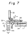
- Fig. 7 is a side view of the upper grippers;
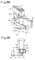
- Figs. 8A and 8B are perspective views of a portion of a main swing arm and a auxiliary film separating means including a auxiliary swing arm;
- Fig. 8C is a partially cross-sectional side view of the auxiliary film separating means;
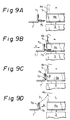
- Figs. 9A to 9D are side views illustrating the operation of the lower grippers;
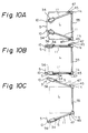
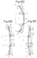
- Figs. 10A to 10F are plan views illustrating the operation of the upper grippers and swing arms;
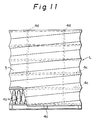
- Fig. 11 is a side view of an example of a palletized and stretch-wrapped load;
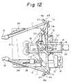
- Fig. 12 is a plan view of a carriage mounted on a second upright frame of the unwrapping apparatus according to the second embodiment of the present invention;
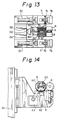
- Fig. 13 is a plan of a cutter unit and lower grippers according to the third embodiment of the present invention;
- Fig. 14 is a side view of the cutter unit of Fig. 13;
- Fig. 15 is a side view of upper grippers according to the fourth embodiment of the present invention;
- Fig. 16 is a plan view of swing arms with the upper grippers of Fig. 15 in a fully extended position;
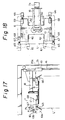
- Fig. 17 is a side view of an unwrapping apparatus including position correcting levers according to the fifth embodiment of the present invention;
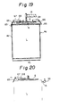
- Fig. 18 is a plan view of a carriage of the unwrapping apparatus of Fig. 17;
- Fig. 19 is a diagrammatic side view of the unwrapping apparatus of Figs. 17 and 18;
- Fig. 20 is a diagrammatic side view of a modified unwrapping apparatus including position correcting levers;
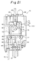
- Fig. 21 is a side view of a used film winding unit adapted for use with the unwrapping apparatus of Fig. 1, for example, and viewed from the arrow XXI in Fig. 22;
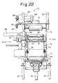
- Fig. 22 is an end view of the used film winding unit of Fig. 21 with the pressure roller at a raised position, and viewed from the arrow XXII in Figs. 21 and 23;
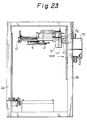
- Fig. 23 is a side view of the used film winding unit of Figs. 21 and 22 and the unwrapping apparatus;
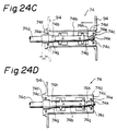
- Fig. 24A to 24D are cross-sectional views illustrating the operation of a mandrel and a discharge plate of Figs. 21 and 22;
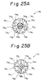
- Figs. 25A and 25B are end views of the mandrel of Figs. 21 and 22;
- Figs. 26A to 26E are diagrammatic views illustrating the operation of the used film winding unit of Figs. 21 and 22;
- Fig. 27 is a side view of a used film wrapping unit adapted for use with the unwrapping apparatus of Fig. 1 and the used stretchable film winding unit of Figs. 21 and 22, for example;
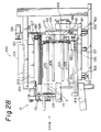
- Fig. 28 is a side view of the used film wrapping unit, viewed from the arrow XXVIII in Fig. 27;
- Figs. 29A and 29B are plan views of the used film wrapping unit of Figs. 27 and 28;
- Figs. 30A and 30B are front views of a turret of Figs. 27 and 28;
- Fig. 31 is a front view of a discharge plate and a pusher plate of Figs. 27 and 28; and
- Figs. 32A to 32D are front views of the used film wrapping unit of Figs. 27 and 28.
- Figure 1 is an overall perspective view of an unwrapping apparatus according to the present invention and Fig. 2 is its elevational side view. The unwrapping apparatus is adapted to unwrap a palletized and stretch-wrapped load L, such as that shown in Fig. 11. In Fig. 11, the load L is comprised of a
pallet 4a, a plurality ofarticles 4b palletized on thepallet 4a and astretchable film 5 wrapping thearticles 4b and thepallet 4a together. In this example, thearticles 4b are empty PET bottles which are placed on thepallet 4a in bulk viaseparate sheets 4c.Straps 4d are applied to the load L before thestretchable film 5 is applied. Thestretchable film 5 includes plural layers encircling thearticles 4b in tension, and may contact thearticles 4b at the peripheral regions of the stretch-wrapped load L. Thestretchable film 5 may enter any gaps or cavities between theseparate sheets 4c or between thepallet 4a and the bottomseparate sheet 4c and shows a concave profile, as shown in Fig. 11. Such a palletized and stretch-wrapped load L can be transported to a user, such as a bottling plant, and unwrapped there. - Referring to Figs. 1 and 2, the unwrapping apparatus includes a
base frame 1, a first frontupright frame 2a and a secondrear upright frame 2b. Achain conveyor 3 is provided on thebase frame 1 for conveying the stretch-wrapped load L to a position between the first and second upright frames 2a and 2b. Of course, the other conveying means such as a roller conveyor or an autoguided vehicle can be used. Aplaten 6 as a pressing means is provided to press a top central region of the palletized load L to stabilize the latter during unwrapping. - As shown in Figs. 1 and 2, and particularly in Figs. 4 and 5, the first
upright frame 2a haslower gripper brackets 50 attached at a lower portion of the firstupright frame 2a on either side thereof.Slidable brackets 51 are positioned on thelower gripper brackets 50, respectively, and securelower grippers 7 thereon, respectively, so that thelower grippers 7 with theslidable brackets 51 are movable toward and away from the load L, as shown by the arrow A.Pneumatic cylinders 30 are provided to move theslidable brackets 51, respectively. Each of thelower grippers 7 has a verticalstationary jaw 7a and amovable jaw 7b, as shown in Fig. 5. Themovable jaw 7b is moved toward and away from thestationary jaw 7a for the gripping action by apneumatic cylinder 31, as shown by the arrow B. - The first
upright frame 2a also has avertical slide guide 52 at the inner side thereof facing the secondupright frame 2b. Acutter unit slider 53 is engaged with thevertical slide guide 52 for upward and downward movement along the firstupright frame 2a, as shown by the arrow C. Anelectric motor 21 moves thecutter unit slider 53 upwards and downwards along thevertical slide guide 52 via a chain or the like (not shown). Thecutter unit slider 53 supports two pairs ofpinch rollers 8 and anelectric heat cutter 9 adapted to cut thestretchable film 5. As shown in Figs. 4 and 6, theheat cutter 9 extends between the twolower grippers 7 toward the palletized load L, and the two pairs ofpinch rollers 8 are arranged on either side of theheat cutter 9, and just above theheat cutter 9. As shown in Fig. 4, thepinch rollers 8 of each pair contact each other and the contact surface between thepinch rollers 8 of each pair extends generally on a line passing through the vertical plane of thestationary jaws 7a of thelower grippers 7. Since thelower grippers 7 grip the lower edge of thestretchable film 5 of the stretch-wrapped load L with thestretchable film 5 rested against thestationary jaws 7a, it will be understood that one of each pair ofpinch rollers 8 is positionable on the exterior side of thestretchable film 5 of the stretch-wrapped load L, and the other on the interior side of thestretchable film 5 to grip thestretchable film 5 therebetween. Anelectric motor 22 drives (or rotates) thepinch rollers 8 via abelt 54. - As shown in Figs. 1 to 3, the second
upright frame 2b has avertical slide guide 16 at the inner side thereof facing the firstupright frame 2a. Acarriage 19 is engaged with thevertical slide guide 16 for upward and downward movement along the secondupright frame 2b, as shown by the arrow D. Anelectric motor 20 moves thecarriage 19 upwards and downwards via a chain or abelt 20a. Thecarriage 19 has a swingarm support frame 55 fixed to the free end of thecarriage 19 and aplaten arm 18 extending from the central position of the swingarm support frame 55. Theplaten arm 18 supports theplaten 6. The swingarm support frame 55 horizontally extends perpendicular to a plane including the first and the second upright frames 2a and 2b and is located at such a position that the swingarm support frame 55 is slightly behind the stretch-wrapped load L to be unwrapped, as shown in Fig. 1. The length of the swingarm support frame 55 is slightly larger than one side of the stretch-wrapped load L. - A pair of
main swing arms 11 are pivotally mounted, respectively, on either end of the swingarm support frame 55 by pivots 11C and symmetrically arranged on either side of theplaten 6. Themain swing arms 11 extend from the swingarm support frame 55 toward the firstupright frame 2a and have respective pivot ends 11C and free ends provided withupper grippers 10 havingmovable jaws stretchable film 5 of the stretch-wrapped load L to be unwrapped.Pneumatic cylinders 35 having marketable proportional flow control valves andpivot levers 11d are associated with themain swing arms 11, respectively, to cause themain swing arms 11 to swing relative to the swingarm support frame 55, as shown by the arrow E. Note, by employing marketable proportional control valves for thepneumatic cylinders 35 instead of electromagnetic valves of conventional ON-OFF type, it is possible not only to infinitely adjust the speed of the swing motion (constant rotational speed) of themain swing arms 11, but also to change the speed during the swing motion of themain swing arms 11, as desired, for cooperation with the swing motion ofauxiliary swing arms 45. It is also possible to instantaneously stop the swing motion of themain swing arms 11 as desired. - As shown in Fig. 2, 3 and 7, each of the
upper grippers 10 is attached to the respectivemain swing arm 11 via aslidable gripper plate 56 and aslidable elevator plate 57, and thus movable toward and away from the stretch-wrapped load L, as shown by the arrow F, and upward and downward, as shown by the arrowG. Pneumatic cylinders 34 are associated with theslidable gripper plates 56, andpneumatic cylinders 32 are associated with theelevator plate 57, for this purpose. Theupper gripper 10 is attached to theslidable elevator plate 57 by apneumatic cylinder 33 and a rack and pinion which opens and closes themovable jaws upper gripper 10 for a gripping action, as shown by the arrow H. - As shown in Figs. 1, 3, and 8A to 8C, a pair of auxiliary film separating means are pivotally provided on the swing
arm support frame 55 near thepivot 11c of themain swing arms 11. As best seen in Figs. 8A to 8C, each of the auxiliary film separating means comprises aauxiliary swing arm 45 having a length shorter than that of themain swing arm 11 and a verticallyretractable pin 46 carried by theauxiliary swing arm 45. Abracket 48a is attached to the bottom of the swingarm support frame 55 inboard of thepivot 11c of themain swing arms 11, and a pneumaticrotary actuator 48 is supported by thebracket 48a. The pneumaticrotary actuator 48 includes a vertically arrangedrotatable shaft 48c that carries theauxiliary swing arm 45. The pneumaticrotary actuator 48 can be a commercially available actuator that may include a pneumatically actuated and horizontallyreciprocable piston 48d and a mechanism such as a rack-and-pinion mechanism 48e-48f for transmitting the linear motion of the piston to the rotational motion of therotatable shaft 48c, whereby theauxiliary swing arm 45 can swing within a predetermined angular range of at least 90 degrees, as shown by the arrow J. Thepin 46 is attached to a piston of thepneumatic cylinder 47, which is fixed to the swingarm support frame 55, and thepin 46 is vertically retractable and extendable, as shown by the arrow K. - The
auxiliary swing arm 45 and thepin 46 are arranged to engage two corner portions of thestretchable film 5 on the rear side thereof, i.e., on the side of the secondupright frame 2b to separate thestretchable film 5 from the corner portion of the load L. - Further, a
pusher bracket 58 extends perpendicularly from theplaten arm 18 and supports a horizontalpneumatic cylinder 36 that has a piston rod securing apusher 12. Thepusher 12 is arranged below the swingarm support frame 55 and is movable toward and away from the swingarm support frame 55, as shown by the arrow I in Fig. 3. Thecarriage 19 also has a ring-like collecting guide 13 arranged in alignment with thepusher 12. The collectingguide 13 has a circular or a trumpet-shaped opening into which thepusher 12 can be inserted. Thepusher 12 forces thestretchable film 5 into the collectingguide 13 as soon as thestretchable film 5 is cut and separated from the palletized load L.The collecting guide 13 thus collectively guides the usedstretchable film 5. In addition, a pair of discharge niprollers 14 are arranged on the outlet side of the collectingguide 13 to continuously compress and discharge thestretchable film 5. - Further, an
impulse heatsealer 15 is provided in thecarriage 19. Thecarriage 19 supports a verticalpneumatic cylinder 37 having a piston rod which in turn carries a horizontalpneumatic cylinder 38. Theheatsealer 15 is carried by the piston rod of the horizontalpneumatic cylinder 38. Therefore, theheatsealer 15 can be moved upwards and downwards, and toward and away from the stretch-wrapped load L. As shown in Figs. 1 and 3, theheatsealer 15 is located at such a position that it can engage with the rear side of the stretch-wrapped load L, to heatseal and join together the plurality of layers of thestretchable film 5. If a top cover is provided on the load L, theheatsealer 15 can join the top cover and thestretchable film 5, to unitize them together to discharge them through thepusher 12, the collectingguide 13 and the discharge niprollers 14. - Further,
sensors 40 to 44 are provided for detecting the positions of the stretch-wrapped load L and the other elements. Thesensors 40 to 44 comprises, for example, beam switches or limit switches. Thesensor 40 detects that the stretch-wrapped load L reaches a predetermined unwrapping position between the first and the second upright frames 2a and 2b. Thesensor 41 detects that theplaten 6 presses the stretch-wrapped load L. Thesensor 42 detects that thecutter unit slider 53 is at a predetermined lower position and thesensor 43 detects that thecutter unit slider 53 is below and near the top of the stretch-wrapped load L. The sensor 44 detects that thecutter unit slider 53 moves above the top of the stretch-wrapped load L. - In operation, the palletized and stretch-wrapped load L is conveyed to the predetermined unwrapping position between the first and the second upright frames 2a and 2b by the
conveyor 3 and stopped there by the output signal of thesensor 40. When the stretch-wrapped load L reaches this position, thelower grippers 7 and thecutter unit slider 53 are waiting in the position of Fig. 2, i.e., the latter just below the former. Thecarriage 19 supporting theplaten 6, theupper grippers 10, themain swing arms 11 and theauxiliary swing arms 45 are in the position of Figs. 2 and 3 above the load L. - When the stretch-wrapped load L is stopped at the predetermined position, the
carriage 19 is moved downwards together with theplaten 6 to press the top of the stretch-wrapped load L, and is stopped by the output signal of thesensor 41. Theupper grippers 10 and thepins 46 are simultaneously lowered but stopped just above the upper edge of the stretch-wrapped load L. - The
movable jaws 7b of thelower grippers 7 are initially in the horizontal positions, as shown in Figs. 5 and 9A. Thelower grippers 7 are first moved toward and beyond the lower edge of thestretchable film 5, as shown in Fig. 9B. Then themovable jaws 7b of thelower grippers 7 are operated to grip thestretchable film 5 between themovable jaws 7b and thestationary jaws 7a, as shown in Fig. 9C. Then thelower grippers 7 are moved away from the lower portion of the palletized load L, as shown in Fig. 9D. Thus a lower portion of thestretchable film 5 is pulled out and separated from thearticles 4b or thepallet 4a to make a gap between the lower portion of thestretchable film 5 and thearticles 4b or thepallet 4a. - Then the
pinch rollers 8 start to rotate and thecutter unit slider 53 is moved upwards along the firstupright frame 2a. Thus thepinch rollers 8 pinch thestretchable film 5 from the exterior side and the interior side thereof and theheat cutter 9 starts cutting thestretchable film 5. Note, thecutter unit slider 53 is set at a position spaced apart from the stretch-wrapped load L and moves along a path designed so that thepinch rollers 8 and theheat cutter 9 do not contact thearticles 4b while thepinch rollers 8 pull out thestretchable film 5, which is initially in close contact with thearticles 4b. - The
cutter unit slider 53 is stopped by the output signal of thesensor 43 located near the top of the stretch-wrapped load L. Then theupper grippers 10 move downwards and are actuated to grip the upper edge of thestretchable film 5 at positions on the outsides of thepinch rollers 8, i.e., on the left and right sides of the pinch rollers, viewed from the front. Then thecutter unit slider 53 is restarted and again stopped in response to the output signal of the sensor 44 located above the top of the stretch-wrapped load L. Thus thestretchable film 5 is completely cut and separated along the cutting line to the left and to the right thereof. In this way, thestretchable film 5 is maintained in tension while thestretchable film 5 is cut since thelower grippers 7 are gripping the lower edge of thestretchable film 5 and theupper grippers 10 are gripping the upper edge of thestretchable film 5. - Finally, the
lower grippers 7 release the lower edge of thestretchable film 5 and theupper grippers 10 move upwards with the actuation of thepneumatic cylinder 32. Simultaneously, themain swing arms 11 are spread from each other with the actuation of thepneumatic cylinders 35. Thus the severed vertical edges of thestretchable film 5 are laterally opened in the front side of the palletized load L (orarticles 4b), and separated from the front side of the palletized load L, as shown in Figs. 10A and 10B. In addition, theslidable gripper plate 56 supported at the free end of themain swing arms 11, and carrying theupper grippers 10, are extended with the actuation of thepneumatic cylinders 34. Therefore, thestretchable film 5 is stretched or pulled and maintained in tension so as not to allow thestretchable film 5 of any shrinkage while thestretchable film 5 is separated from the front side and the lateral sides of the load L, as shown in Figs. 10B and 10C. Thestretchable film 5 is maintained in tension without shrinkage until theswing arms 11 are finally swung to a position, as shown in Fig. 10F. - The movement of the
auxiliary swing arms 45 of the auxiliary film separating means is started an appropriate time after the movement of themain swing arms 11 is started. Themain swing arms 11 are once stopped an appropriate time before the movement of themain swing arms 11 is completed, for example, at a time shown in Fig. 10D, in which eachmain swing arm 11 just extends beyond thepins 46 of the auxiliary film separating means. Thepins 46 are first lowered with the actuation of thepneumatic cylinders 47 so that eachpin 46 enters the gap between the side of the load and the upper edge of thestretchable film 5 near the rear corner portion thereof. Themain swing arms 11 are then restarted to move and theauxiliary swing arms 45 are rotated as shown in Figs. 10D to 10F. Note, the speed of theauxiliary swing arms 45 is higher than that of themain swing arms 11 and theauxiliary swing arms 45 are rotated more than 90 degrees. Accordingly, thepin 46 engages with thestretchable film 5 covering the corner portion of the load L to separate thestretchable film 5 from the corner portion of the load L, as shown in Fig. 8B, while theswing arms 11 are rotating and maintaining the tension in thestretchable film 5. - Preferably, the timing of the operation of the
auxiliary swing arms 45 is such that the movement of theauxiliary swing arm 45 is completed before the movement of themain swing arms 11 is completed, as shown in Fig. 10E, that is, themain swing arms 11 travel beyond the line interconnecting the two rear corners of the load L after theauxiliary swing arm 45 travels beyond that line. Themain swing arms 11 are then further moved to the final position of Fig. 10F, accompanying the retracting movement of theslidable gripper plate 56 relative to themain swing arms 11, and when themain swing arms 11 completely open, thestretchable film 5, thepins 46, theauxiliary swing arm 45 and theplaten 6 are returned to their respective initial positions. It will be understood that the triggering of the pneumatic cylinders and rotary actuator can be modified from that as explained above. - In this way the
stretchable film 5 is fully separated from the palletized load L (or thearticle 4b) without shrinkage. If thestretchable film 5 suddenly shrinks during removal, thearticles 4b in contact with shrinkingfilm 5 may be moved or shifted by the shrinking film and fall down out of thepallet 4a or theseparate sheets 4c. According to the present invention, it is possible to prevent thearticles 4b from falling during unwrapping. - When the
stretchable film 5 is fully separated from the palletized load L (or thepalletized articles 4b), as shown in Fig. 10F, thepusher 12 is moved toward thestretchable film 5 supported by theupper grippers 10 to push it into the collectingguide 13 and the discharge niprollers 14 may be driven. Then theupper grippers 10 release thestretchable film 5 that is being pulled into the collectingguide 13 and the discharge niprollers 14. In this course, thestretchable film 5 is compressed or squeezed into a compact belt-like shape by which it can be easily disposed. - The stretch-wrapped load L thus unwrapped is discharged by the
conveyor 3 at an appropriate time after the end of the swing motion of theswing arms 11. - In the case of a load that is stretch-wrapped after a further film (referred to as a top cover) covers the top of the load L, according to the unwrapping apparatus of the present invention, the
impulse heatsealer 15 is lowered with the actuation of thepneumatic cylinder 37 and advanced toward the load L with the actuation of thepneumatic cylinder 38 so that the plural layers of thestretchable film 5 wound around the periphery of the load L and the top cover are heatsealed together to unitize them at an appropriate time during the time from the stopping of the load L conveyed by theconveyor 3 at the unwrapping position to the completion of the cutting of thestretchable film 5, thereby it is possible to consecutively compress thestretchable film 5, and the top cover and discharge them in a compact belt-like shape. - Figure 12 shows a
carriage 19 according to the second embodiment of the present invention; thecarriage 19 being mounted on the unwrapping apparatus of Figs. 1 to 10F. Thecarriage 19 differs from that of Figs. 1 to 10F in that it includes anelectric servo motor 23, a reduction gear means 24 and pivot levers 11e for actuating themain swing arms 11, in place of thepneumatic cylinders 35 in the previous embodiment. - When a non-cling type film rather than a cling type film is used for the
stretchable film 5, plural layers of thestretchable film 5 wound around the load L are not unitized to each other, and may be separated into individual layers when thestretchable film 5 is cut and then pushed into the ring-likecollective guide 13 after unwrapping. Such separatedstretchable film 5 may hinder the continuous operation of the unwrapping apparatus. - The third embodiment of Figs. 13 and 14 solves this problem. Figs. 13 and 14 shown a cutter unit that can be mounted to the
cutter unit slider 53 of the unwrapping apparatus of Figs. 1 to 10F in place of the corresponding cutter of Figs. 1 to 10F. In this embodiment, the cutter unit includes two pairs of niprollers 8 and aheat cutter 9, and a heatsealer is incorporated in one of each pair of niprollers 8 located on the exterior side of thestretchable film 5 to heatseal thestretchable film 5 continuously in two lines on either side of the cutting line of thestretchable film 5 to unitize the plural layers of strips of thestretchable film 5 together. In particular, as shown in Figs. 13 and 14, thenip roller 8 on the exterior side of thestretchable film 5 comprises a combination of a plurality of different nylon disks to form alarge diameter portion 8m andsmall diameter portions 8n.Nichrome wire 60 is arranged on the peripheral surface of thelarge diameter portion 8m and a layer of polytetrafluoroethylene covers theNichrome wire 60. Slip rings 61 are arranged on thesmall diameter portions 8n for supplying the power to theNichrome wire 60, andpower supply contacts 62 are arranged below thenip roller 8 in contact with the slip rings 61. In addition, another roller on the interior side also comprises a nylon roller that is covered by a layer of silicon rubber and a layer of polytetrafluoroethylene. - In contrast to the above case, when a highly clinging type film is used for the
stretchable film 5, there may be the problem that thestretchable film 5 is not easily separated from theupper grippers 10 when theupper grippers 10 are opened to release thestretchable film 5 after themain swing arms 11 complete the opening of the severedstretchable film 5. - The fourth embodiment of Figs. 15 and 16 solves this problem. The
upper grippers 10 in this embodiment are mounted to theslidable elevator plate 57 via arotary support element 64; theslidable elevator plate 57 being connected to therespective swing arms 11 via theslidable gripper plate 56. Therotary support element 64 comprises a pneumatic rotary actuator similar to the pneumaticrotary actuator 58 and can rotate about a vertical axis, as shown by the arrow P. Theupper grippers 10 are initially arranged at an angle relative to therespective swing arms 11, as shown in Fig. 10A, and the angle between theupper gripper 10 and theswing arm 11 is unchanged during the swing motion of the swing arms 11 (see Fig. 10F). Therotary support element 64 is operated to rotate theupper gripper 10 outwardly about the vertical axis at the free ends of themain swing arms 11 by approximately 90 degrees just after themain swing arms 11 complete the swing motion to open thestretchable film 5 so that theupper grippers 10 are directed generally parallel to theswing arms 11, as shown in Fig. 16. Thestretchable film 5 thus assumes a straight position throughout its length, and is easily separated from theupper grippers 10 because of shrinkage when theupper grippers 10 are operated so as to openjaws upper grippers 10 comprises astationary jaw 10a and amovable jaw 10b. - The articles such as
empty containers 4b are light in weight and are layered so that the load L is frequently as high as approximately 2 meters, and when the load L reaches a user, the load L may not assume an exact upright position but may frequently be sightly inclined from the upright to either side. If the inclined load L is conveyed to the unwrapping position, there is the problem that theupper grippers 10, which are in the initial position, cannot accurately grip the upper edge of thestretchable film 5. - The fifth embodiment of Figs. 17 to 19 solves this problem. In this embodiment, at least one position correcting means 65 or 66 is provided for engagement with an upper edge of the stretch-wrapped load L to correct the position of load L in relation to the position of the
upper grippers 10. The position correcting means comprises at least a correctingguide - In the preferred embodiment, two pairs of the correcting
guides platen 6, which is H-shaped. Thisplaten 6 is modified from the circular one in Fig. 1. The correcting guides 65 are located at the front edges of the H-shapedplaten 6 on the side of the firstupright frame 2a and theother levers 66 are located at the rear edges of the H-shapedplaten 6 on the side of the second upright frame. The front correctingguides 65 are mounted on the front lever tilting means 67 comprising plates pivotally securing thefront correcting guides 65 and pneumatic cylinders causing the pivotal motion of the front correctingguides 65, respectively. The front lever tilting means 67 is supported on theplaten 6 via front lever retractingpneumatic cylinders 68. Therear correcting guides 66 are mounted on the rear lever tilting means 69 also comprising plates pivotally securing therear correcting guides 66 and pneumatic cylinders causing the pivotal motion of therear correcting guides 66, respectively. The rear lever tilting means 69 is directly supported on theplaten 6. - Accordingly, the correcting
guides - The front correcting
guides 65 are initially in the first horizontal and retracted positions and therear correcting guides 66 are initially in the first horizontal positions. When the load L reaches the unwrapping position, thefront correcting guides 65 are advanced and moved from the first horizontal position to the second downwardly tilted position and therear correcting guides 66 are moved from the first horizontal position to the second downwardly tilted position. The front and rear correctingguides platen 6 to engage with the respective upper edges of the stretch-wrapped load L. - If the load L is in a precise upright position, the front and the
rear correcting guides rear correcting guides guides rear correcting guides upper grippers 10 can grip the upper edge of thestretchable film 5 when the cutter unit reaches the predetermined height of the load L. The load L may includestraps 4d (Fig. 19) that will get fit with the corrected load L. - When the continuously descending
platen 6 approaches a position near the top of the load L, such as a position shown in Fig. 17, the front and rear correctingguides guides 65 are retracted over the load L. The unwrapping operation is carried out in a manner previously described. - The
main swing arms 11 can swing in a horizontal plane above the correctingguides upper grippers 10 carried by themain swing arms 11 or the stretchable film gripped by the latter may be interfered with by the front correcting guides 65. Accordingly, thefront correcting guides 65 are retracted. - Figure 20 shows a modified unwrapping apparatus, including correcting guides. In this embodiment, the position correcting means comprises front correcting
guides 65 similar to those in the previous embodiment, and aheatsealer 15 arranged on the rear side of the load L. Thisheatsealer 15 corresponds to that shown in Fig. 1 carried by the horizontalpneumatic cylinder 38, which is in turn carried by the verticalpneumatic cylinder 37. It will be understood that theheatsealer 15 can push the load L if the position of the load L is incorrect. - Figures 21 to 26D show a used stretchable
film winding unit 70 attached to the second or rearupright frame 2b of the unwrapping apparatus, as shown in Fig. 23. The used stretchablefilm winding unit 70 can be attached to another suitable stationary frame. The unwrapping apparatus has the ring-like collecting guide 13 and the discharge niprollers 14, through which the used (separated from the load L)stretchable film 5 is discharged in a compacted belt-like shape, as previously described. A transferringguide 71 is arranged between the discharge niprollers 14 and the used stretchablefilm winding unit 70 to transfer the usedstretchable film 5 to the used stretchablefilm winding unit 70. There is asensor 72 above the transferringguide 71 for detecting the transfer of the usedstretchable film 5. - Figure 21 is a side view of the
unit 70 viewed from the arrow XXI in Fig. 22, and Fig. 22 is an end view of theunit 70 viewed from the arrow XXII in Figs. 21 and 23. Figs. 24A to 24D illustrate the operation of a mandrel and a discharge plate of Figs. 21 and 22, Figs. 25A and 25B are end views of the mandrel of Figs. 21 and 22, and Figs. 26A to 25E illustrate the operation of theunit 70. - As shown in Figs. 21 and 22, the used
film winding unit 70 comprises amain frame 73 including anopening 73a at one side thereof and amandrel 74 extending horizontally and perpendicular to a line interconnecting the first and second upright frames 2a and 2b and perpendicular to theopening 73a such that a roll of thestretchable film 5 can be discharged from theopening 73a. Apressure roller 75 is arranged parallel to and above themandrel 74; thepressure roller 75 being urged to and brought into contact with themandrel 74 to rotate there with. Asupport belt 84 is brought into contact with a portion of themandrel 74 on the opposite side of thepressure roller 75 to rotate with themandrel 74, and adischarge plate 94 is arranged on one end of themandrel 74 so as to travel along the length of themandrel 74 to push and remove the roll of thestretchable film 5 wound on themandrel 74 from themandrel 74. Themandrel 74 has a variable diameter, so that thestretchable film 5 is wound on themandrel 74 with a large diameter, and when the roll of thestretchable film 5 is pushed by thedischarge plate 94, the diameter of themandrel 74 attains a small diameter. - As shown in Figs. 24A to 25B, the
mandrel 74 comprises a support shaft 74a, aninner shaft 74b connected to the support shaft 74a, and anouter split sleeve 74c comprising four circumferentially spaced quarter cylindrical sections about theinner shaft 74b and covered by aslidable plastic layer 74d. These four quarter cylindrical sections of theouter split sleeve 74c are interconnected by elastic O-rings 74e. Theouter split sleeve 74c has aradial flange 74f at one end thereof against which thedischarge plate 94 abuts. - The
inner shaft 74b has taperedouter surface portions 74g and theouter split sleeve 74c has correspondingly taperedinner surface portions 74h. Theouter split sleeve 74c is axially slidable relative to theinner shaft 74b with the taperedinner surface portions 74h engaging with the taperedouter surface portions 74g so that when theouter split sleeve 74c is at the left position it provides a large diameter and when theouter split sleeve 74c is moved to the right position it provides a small diameter. Theinner shaft 74b has outwardly projecting pins 74i and theouter split sleeve 74c has correspondingly recessedgrooves 74j for axially guiding theouter split sleeve 74c along theinner shaft 74b. In addition, theinner shaft 74b has astopper 74k at one end thereof opposite theradial flange 74f of theouter split sleeve 74c to restrict the movement of theouter split sleeve 74c. Also, theouter split sleeve 74c haslateral grooves 74p on the outer peripheral surface thereof, and a layer of plastics material having a good slidable properties may be coated on the outer peripheral surface of theouter split sleeve 74c. - As shown in Figs. 21 and 22, the mandrel 74 (the support shaft 74a) is connected for rotation to an
electric motor 88 via sprockets 89 to 91 and achain 92. Thedischarge plate 94 is actuated by apneumatic cylinder 95. Thepressure roller 75 is not driven but urged to themandrel 74 bypneumatic cylinders 93 so as to rotate with themandrel 74. Thesupport belt 84 embracing themandrel 74 from below is carried in asupport belt unit 76 including abelt frame 77,brackets 78 fixed to thebelt frame 77 andpneumatic cylinders 79 connected to thebelt frame 77 for upwardly and downwardly moving thebelt frame 77. Thesupport belt 84 is passed aroundguide rollers 80 to 83 rotatably attached to thebrackets 78 and thebelt frame 77. Thesupport belt 84 is engaged with atension roller 85 that is guided along aguider 86 and actuated bypneumatic cylinders 87 fixed to thebelt frame 77. - Also, a
heatsealer roller 96 is provided parallel to themandrel 74 and supported by apneumatic cylinder 97 for movement toward and away from themandrel 74 so as to join together plural layers of thestretchable film 5 wound around themandrel 5. - During operation of the used
film winding unit 70, the usedstretchable film 5 in a compacted belt-like shape discharged from the ring-like collecting guide 13 and the discharge niprollers 14 is transferred to the used stretchablefilm winding unit 70 through the transferringguide 71. Thesensor 72 above the transferringguide 71 detects the transfer of the usedstretchable film 5 and activates themotor 88 to rotate themandrel 74. - As shown in Fig. 26A, the
pressure roller 75 is urged from above to themandrel 74 by thepneumatic cylinders 93, and thesupport belt 84 is urged from below to themandrel 74 by thetension roller 85 with thesupport belt unit 76 raised by thepneumatic cylinders 87. Thestretchable film 5 in belt-like form is introduced into the gap between themandrel 74 and thepressure roller 75 to be compressed flat and further introduced into the gap between themandrel 74 and thesupport belt 84 to thereby be wound around themandrel 74 into a roll ofstretchable film 5. At the beginning of the winding, thelateral grooves 74p of theouter split sleeve 74c of themandrel 74 serves to bite therein the leading edge of thestretchable film 5 with the cooperation of thepressure roller 75. - As shown in Figs. 26B and 26C, as the winding of the
stretchable film 5 advances, tension is applied to thestretchable film 5 between themandrel 74 and the discharge niprollers 14 since the circumference of the woundstretchable film 5 per revolution of themandrel 74 increases, resulting in thestretchable film 5 urging themandrel 74 and being tightly wound. As the diameter of the woundstretchable film 5 increases, thecompression roller 75 is urged upwards and the portion of thesupport belt 84 around themandrel 74 is urged downwards with the corresponding downward movement of thetension roller 85 along theguider 86 to compensate the length of thesupport belt 84. - When a predetermined time passes after the
sensor 72 above the transferringguide 71 has detected the trailing edge of thestretchable film 5, thepneumatic cylinders 79 are actuated to lower thebelt frame 77 so that all the components of thesupport belt unit 76 are lowered, as shown in Fig. 26D. Themotor 88 with themandrel 74 is further rotated and theheatsealer roller 96 is moved toward themandrel 74 with the actuation of thepneumatic cylinder 97 to join together plural layers ofstretchable film 5 wound around themandrel 5 to prevent the winding end portion of the roll ofstretchable film 5 from loosening. Note, it is necessary to heatseal the winding end portion of the roll of thestretchable film 5 if thestretchable film 5 is of non-cling type but it is not necessary to heatseal thestretchable film 5 if it is of cling type. - Then, as shown in Fig. 26E, the
compression roller 75 is raised with the actuation of thepneumatic cylinder 93 and theheatsealer roller 96 is moved away from themandrel 74 with the actuation of thepneumatic cylinder 97. Themotor 88 with themandrel 74 is stopped. - Figure 24A is a side cross-sectional view of the
mandrel 74 in the condition of Fig. 26E. Thedischarge plate 94, which is initially located on theflange 74f at the left end of themandrel 74, is then moved to the right with the actuation of thepneumatic cylinder 95 so as to push thestretchable film 5, as shown in Figs. 24A and 24B. As described above, thestretchable film 5 is wound around themandrel 74 under tension and thereby compresses themandrel 74, so that when thedischarge plate 94 pushes thestretchable film 5, thestretchable film 5 is not released from theouter split sleeve 74c but moves with theouter split sleeve 74c to the right, and when theouter split sleeve 74c is moved to the right by the distance m, that is, when theouter split sleeve 74c is moved relative to theinner shaft 74b along the correspondingly tapered outer andinner surface portions outer split sleeve 74c abuts against thestopper 74k at the right end of theinner shaft 74b, the diameter of theouter split sleeve 74c changes from a large diameter of Fig. 25A to a small diameter of Fig. 25B. Accordingly, thestretchable film 5 can be easily released from theouter split sleeve 74c along theslidable plastic layer 74d by further movement of thedischarge plate 94 to the position shown by the semi-broken line in Fig. 24B and by the solid line in Fig. 24C, and the roll ofstretchable film 5 is discharged from theopening 73a in themain frame 73 along themandrel 74. - The
discharge plate 94 is then returned from the right discharge position to the left position to abut against theflange 74f of theouter split sleeve 74c and further to the initial left position, thereby pushing theouter split sleeve 74c to its initial position, in which it has a large diameter, as shown in Fig. 24D. Thecompression roller 75 and thesupport belt unit 76 are then returned to urge themandrel 74 with the actuation of thepneumatic cylinders rollers 14 and the cycle is repeated. - The used
film winding unit 70 can be used with an unwrapping apparatus other than that shown in Fig. 1. In this case, the collectingguide 13 and the discharge niproller 14 are preferably added to such an unwrapping apparatus. Also, it is possible to use a type of mandrel other than themandrel 74, such as a mandrel having a diameter variable with the use of pneumatic pressure or other known expansion type mandrels. - Figures 27 to 32D show a used stretchable
film wrapping unit 100 adapted for use with the unwrapping apparatus of Fig. 1 and the usedfilm winding unit 70 of Fig. 21. - As shown in Figs. 29A and 29B, the used
film wrapping unit 100 is arranged on the side of theopening 73a in themain frame 73 of the usedfilm winding unit 70, and comprises a plurality of (four in the embodiment)mandrels 109 carried by arotatable turret 105 arranged on the side of themandrels 109 remote from the usedfilm winding unit 70 so that one of themandrels 109 is brought into alignment with themandrel 74 of the usedfilm winding unit 70 so that the roll of thestretchable film 5 can be transferred from themandrel 74 to themandrel 109. Each of themandrels 109 has sufficient length to receive a plurality of rolls of thestretchable film 5. Theturret 105 is operatively connected to an electric motor 134 (Fig. 28) that is controlled by an appropriate control means (not shown) so that theturret 105 is stepwise rotated at an angle of 90 degrees, or 360 degrees (or multiple times of 90 degrees). - Referring to Figs. 27 and 28, the used
film wrapping unit 100 comprises aunit base 101 that supportsturret 105 with themandrels 109 and is displaceably supported on ahorizontal rail 103 viacaster wheels 102. Theunit base 101 is moved transversely of themandrels 109 between a first position in which theturret 105 with themandrels 109 faces the used film winding unit 70 (Fig. 29A) and a second position in which theturret 105 with themandrels 109 faces an inclined roller conveyor 104 (Fig. 29B) by apneumatic cylinder 137. Themovable unit base 101 also supports most components of the usedfilm wrapping unit 100, described below. - The used
film wrapping unit 100 comprises adischarge plate 106 havingslots 115 for passing themandrels 109 therethrough, asupply device 107 of awrapping film 124 for wrapping the rolls of thestretchable film 5 on themandrels 109, and aheatsealer 108 to join together the plural layers of thewrapping film 124 wrapping the rolls of thestretchable film 5. - The
discharge plate 106 is supported by apusher plate 118 arranged parallel to and in front of theturret 105. Thepusher plate 118 is displaceably supported onlinear ways 122 extending parallel to themandrels 109 and fixed to theunit base 101.Feed nuts 120 are fixed to the bottom of thepusher plate 118 and engaged byfeed screws 121 extending parallel to the linear ways. Anelectric motor 135 is operatively connected to rotate the feed screws 121. - As shown, particularly in Fig. 31, the
pusher plate 118 has a largecircular opening 119 that allows all themandrels 109 to pass therethrough. Thedischarge plate 106 is a circular plate having a diameter slightly larger than that of thecircular opening 119 and is concentrically arranged with thecircular opening 119. Thedischarge plate 106 is rotatably supported to thepusher plate 118 by radially arrangedsupport bearings 116 that engage with the front peripheral surface of thedischarge plate 106 to retain the latter and radially arrangedsupport rollers 117 that engage with the outer periphery of thedischarge plate 106. Thedischarge plate 106 is thus freely rotatable relative to thepusher plate 118. - The
discharge plate 106 has equiangularly arrangedslots 115 to allow themandrels 109 to pass therethrough, respectively. That is, thedischarge plate 106 can move along themandrels 109 by the operation of the feed screws 121. Theslots 115 extend radially about the center of thedischarge plate 106 and have an arcuate shape. Themandrels 109 can rotate about the center of thedischarge plate 106 with the latter and can move radially of thedischarge plate 106 along thearcuate slots 115, respectively. - As shown in Figs. 28, 30A and 30B, the
mandrels 109 are equiangularly arranged and secured to theturret 105 vialevers 110, respectively. Eachlever 110 extends parallel to theturret 105 and has asupport shaft 111 integral with thelever 110. Thesupport shaft 111 is rotatably supported on theturret 105 and secures asprocket wheel 112 thereon. Apneumatic cylinder 138 having an oppositely extending piston rod is arranged at the center of theturret 105. Twochains 114 are provided, each one extending around twosprocket wheels 112 andtensioners 113 with one end of thechain 114 being attached to one end of the oppositely extending piston rod of thepneumatic cylinder 138 and the other end of thechain 114 being attached to the other end of the piston rod. When thepneumatic cylinder 138 is operated so that the piston rod thereof is moved to the right in Fig. 30A, thechain 114 moves in the direction of the arrow to rotate thesprocket wheels 112 within 90 degrees of angle to thereby cause thelevers 110 to rotate anticlockwise. Accordingly, themandrels 109 move to a radially outer position along an arcuate path, which is defined in theslots 115. When thepneumatic cylinder 138 is operated reversely, thechain 114 moves in the direction of the arrow in Fig. 30B thereby causing thelevers 110 to rotate clockwise. Accordingly, themandrels 109 move to a radially inner position along the arcuate path. That is, each of themandrels 109 is carried by thelever 110 to theturret 105 and displaceable along a predetermined path between a first position in which themandrels 109 are standing in a first circle and a second position in which themandrels 109 are standing in a second circle concentric with and smaller than the first circle. - As shown in Figs. 27 and 28, the
supply device 107 of thewrapping film 124 is arranged above themandrels 109 carried by theturret 105 and comprises a pair ofbearer rollers 125 on which aroll 123 of thewrapping film 124 rests. A brake is provided for braking the unwoundwrapping film 124. A pair offeed rollers 126 are arranged below thebearer rollers 125 and actuated by a gearedmotor 136 to unwind the web of thewrapping film 124 from theroll 123 on thebearer rollers 125 so as to feed the same downwards through thefeed rollers 126. - In addition, the
feed rollers 126 have respective shafts to whicharms 127 are mounted via ratchets, respectively. One of thearms 127 has at the bottom thereof aheat cutter 128 and theother arm 127 has at the bottom thereof ananvil 129. Thearms 127 are normally in an open position shown in Fig. 27, by aspring 132 biasing one of thearms 127. One of thearms 127 also has afilm holder 130 just above theheat cutter 128 and theother arm 127 also has acushion 131 just above theanvil 129. - When the
motor 136 is rotated in one direction, thefeed rollers 126 are rotated to feed the web of thewrapping film 124 downwards but thearms 127 remain in the position of Fig. 27 by the action of the ratchets. When themotor 136 is rotated in reverse, thefeed rollers 126 are rotated in reverse and thearms 127 are closed, as shown in Fig. 32D, by the action of the ratchets. Accordingly, the web of thewrapping film 124 is cut between theheat cutter 128 and theanvil 129, and in this case, the severed end of thewrapping film 124 extending from theroll 123 is held and stabilized between thefilm holder 130 and thecushion 131. - The
heatsealer 108 is carried by a bottom end of a piston rod of apneumatic cylinder 139 that is mounted on a stationary frame member of thesupply device 107. Afilm holding bar 138 is also carried by the piston rod of thepneumatic cylinder 139 and extends to a position near theheatsealer 108. Theheatsealer 108 with thefilm holding bar 138 is advanced toward the rolls of thestretchable film 5 received in themandrels 109 to heat seal together thestretchable film 5 and thewrapping film 124 to be wound around the rolls of thestretchable film 5 before wrapping or to heat seal the plural layers of thewrapping film 124 together after wrapping, as shown in Fig. 32C. Thefilm holding bar 133 presses and stabilizes thewrapping film 124 upon heatsealing. - During the operation of the used
film wrapping unit 100, theunit base 101 is first moved to the position of Fig. 29A, and one of themandrels 109 is brought into alignment with themandrel 74 of the usedfilm winding unit 70. Thedischarge plate 94 of the usedfilm winding unit 70 then pushes the roll of thestretchable film 5 onto themandrel 109 of the usedfilm wrapping unit 100, as shown in Figs. 29A and 32A. The operation of the usedfilm winding unit 70 is repeated until four rolls, for example, of thestretchable film 5 are received on themandrel 109. Then theturret 105 is rotated with the actuation of themotor 134 at an angle of 90 degrees so that thenext mandrel 109 is brought into alignment with themandrel 74. Similarly, four rolls of thestretchable film 5 are then received on thatmandrel 109. Theturret 105 is then further rotated at an angle of 90 degrees and thethird mandrel 109 receives four rolls of thestretchable film 5, and thefourth mandrel 109 also receives four rolls of thestretchable film 5. This is shown in Fig. 32B. - When the four
mandrels 109 are fully loaded with the rolls of thestretchable film 5, thepneumatic cylinder 138 is actuated from the position of Fig. 30A to the position of Fig. 30B, so that themandrels 109 are moved inwardly of theturret 105, as shown in Fig. 32B. Themotor 136 of the wrappingfilm supply device 107 is then rotated so that thefeed rollers 126 are rotated to feed the web of thewrapping film 124 until thewrapping film 124 reaches the side surface of the uppermost mandrel 109 (see theleading edge portion 124a of thewrapping film 124 in Fig. 32C). Note, the dischargingplate 106 rotates relative to thestationary pusher plate 118, following therotating mandrels 109. - The
heatsealer 108 is then advanced with the actuation of thepneumatic cylinder 139 so that the hangingwrapping film 124 is joined to the surface of the rolls of thestretchable film 5 held on theuppermost mandrel 109. After theheatsealer 108 retreats, theturret 105 is rotated at an angle of 360 degrees so that thewrapping film 124 encircles the four rows of the rolls of thestretchable film 5. Then theheatsealer 108 is again advanced to heat-seal the layers of the wrapping film, i.e., the leadingedge portion 124a and the trailing edge portion of thewrapping film 124 are heat sealed together to complete a package. It is, of course, possible to rotate theturret 105 two or three turns to encircle the rolls of thestretchable film 5 twice or thrice. Themotor 136 is then rotated in reverse so that thefeed rollers 126 are rotated in reverse and thearms 127 are closed, as shown in Fig. 32D. Thewrapping film 124 is cut between theheat cutter 128 and theanvil 129. If the length of a portion of thewrapping film 124 between the severed end and the sealed point is long, it is possible to further rotate theturret 105 at an angle of 90 degrees and further heatseal the excess portion. - The
unit base 101 is then moved to the position of Fig. 29B with the actuation of thepneumatic cylinder 137, where themandrels 109 face theinclined roller conveyor 104. This operation can be carried out at a prior stage after the fourmandrels 109 are loaded with the rolls of thestretchable film 5. Thepusher plate 118 with the dischargingplate 106 is then advanced toward theinclined roller conveyor 104 on thelinear way 122 along the length of themandrels 109 with the actuation of themotor 135 rotating thefeed screw 121 relative to thefeed nut 120 pushing the package of thestretchable film 5 by the dischargingplate 106, and thus, removing the rolls of thestretchable film 5 from themandrels 109. Accordingly, the package of thestretchable film 5 is discharged to theinclined roller conveyor 104, from which the package of thestretchable film 5 is further conveyed to an appropriate box or the like for recycling of thestretchable film 5 and thewrapping film 124. The elements are returned to their initial position and the cycle is repeated.
Claims (22)
- An unwrapping apparatus for unwrapping a load comprised of pallet, a plurality of articles palletized on the pallet and a stretchable film wrapping the articles and the pallet together, said unwrapping apparatus comprising:first and second upright frames (2a, 2b) arranged in a spaced relationship;means (3) for conveying a load to be unwrapped at a position between the first and the second upright frames (2a, 2b);a cutter unit (9) arranged for upward and downward movement relative to the upright frames (2a, 2b) for vertically cutting the stretchable film;lower gripper means (7) arranged for gripping a lower portion of a stretchable film of a load to be unwrapped;a pair of swing arms (11), eg. actuable by pneumatic cylinder means or by servo-motor means;an upper gripper (10) arranged on the free end of each of the swing arms (11) for gripping an upper portion of the stretchable film of the load, whereby the stretchable film that is cut by the cutter unit (9) and gripped by the upper grippers (10) is spread and separated from the load during a swing motion of the swing arms (11); and characterised in that:said lower gripper means (7) are arranged on or near the first upright frame (2a), and said cutter unit (9) is arranged on the first upright frame (2a); and by:a carriage (19) arranged on the second upright frame (2b) for upward and downward movement along the second upright frame (2b) and having pressing means (6) to press the top of the load to be unwrapped so as to stabilize the same while being unwrapped;said pair of swing arms (11) being symmetrically arranged on either side of the pressing means (6) with pivot ends on the side of the second upright frame (2b) and free ends on the side of the first upright frame (2a); anda pair of auxiliary film separating means (45, 46) operable in synchronism with the movement of the swing arms (11) for engagement with corner portions of the stretchable film on the side of the second upright frame (2b) to separate the stretchable film from the corner portions of the load.
- An unwrapping apparatus according to claim 1, characterised in that the lower gripper means comprises two lower grippers (7) arranged on the first upright frame (2a) in a horizontally side by side relationship for gripping a lower edge of the stretchable film on the load to be unwrapped each of the lower grippers (7) being movable toward and away from the load;the cutter unit being arranged on the first upright frame (2a) between the two lower grippers (7) for upward and downward movement along the first upright frame (2a), said cutter unit having two pairs of pinch rollers (8) with one of each pair of pinch rollers (8) positionable on the exterior side of the stretchable film and the other on We interior side of the stretchable film to grip the stretchable film there between, and cutting means (9), e.g. an electric cutter, arranged between the two pairs of pinch rollers (8) for cutting the stretchable film;the carriage (19) including a support frame (55) extending perpendicular to a line interconnecting the first and the second upright frames (2a, 2b), said support frame (55) carrying the swing arms (11) and the auxiliary film separating means (45, 46); and wherein, optionally,at least one of the pinch rollers (8) of the cutter unit has heatsealing means incorporated therein to join together plural layers of the stretchable film.
- An unwrapping apparatus according to claim 2, characterised in that the auxiliary film separating means (45, 46) are pivotally carried by the support frame (55) of the carriage (19) at positions on or near the respective pivot ends of the swing arms (11).
- An unwrapping apparatus according to claim 2 or 3, characterised in that the upper grippers (10) are movable upwards and downwards relative to and toward and away from the respective swing arms (11), and wherein the swing arms (11) are initially arranged so that the distance between the free ends thereof is smaller than the distance between the pivot ends thereof, and are then in use swung outwardly about the respective pivot ends simultaneously with the forward movement of the upper grippers (10) by extending the swing arms (11) after the stretchable film is cut, thereby to maintain tension on the stretchable film while the stretchable film is separated from the load.
- An unwrapping apparatus according to claim 4, characterised in that the upper grippers (10) are further movably arranged so as to horizontally and outwardly rotate about the respective free ends of the swing arms (11) to a position in which the upper grippers (10) are generally parallel to the swing arms (11) when the latter are fully swung.
- An unwrapping apparatus according to claim 4 or 5, characterised in that the movement of the auxiliary film separating means (45, 46) is completed before We movement of the swing arms (11) is completed, and wherein preferably it is started after the movement of the swing arms (11) is started.
- An unwrapping apparatus according to any of claims 4 to 6, characterised in that each of the auxiliary film separating means comprises an auxiliary swing arm (45) having a length shorter than that of the swing arms (11), and a vertically retractable pin (46) carried by the auxiliary swing arm (45).
- An unwrapping apparatus according to claim 7, characterised in that the auxiliary swing arm (45) is carried by the support frame (55) of the carriage (19) via a rotary actuator (48), e.g. one that is operable within a predetermined angular range of at least 90 degrees, and the retractable pin (46) is carried by the auxiliary swing arm (45) via e.g. a vertical pneumatic cylinder.
- An unwrapping apparatus according to claim 2, characterised in that the heatsealing means (60) is incorporated in the nip roller so as to be positioned on the exterior side of the stretchable film, and wherein the heatsealing means (60) preferably comprises an electrical resistance wire wound around the nip roller, a slip ring means (61) connected to the electrical resistance wire, and power supply contact means (62) for the slip ring means (61), and an electrically insulating layer covering the electrical resistance wire.
- An unwrapping apparatus according to any preceding claim, characterised in that the carriage (19) further includes a heatsealing means (15) for movement upwards and downwards, and toward and away from the load to join together plural layers of the stretchable film and a top cover if provided.
- An unwrapping apparatus according to any preceding claim, characterised in that at least one position correcting means (65, 66) is provided for engagement with an upper edge of the stretch-wrapped load to correct the position of the load in relation to the position of the upper grippers (10).
- An unwrapping apparatus according to claim 11, characterised in that the position correcting means comprises a correcting guide (65, 66) located above the load to be unwrapped; the correcting guide (65, 66) being capable of moving from a first horizontal position on the outside of the load to a second downwardly tilted position toward the load to thereby engage with an upper edge of the stretchable film; orthe position correcting means comprises at least one pair of correcting guides (65, 66) located above the load to be unwrapped, one of each pair of the correcting guides (65, 66) being located on the side of the first upright frame (2a) and being preferably capable of moving toward and away from the load, the other guide on the side of the second upright frame (26), and the correcting guides (65, 66) being capable of moving from a first horizontal position on the outside of the load to a second downwardly tilted position toward the load to thereby engage with an upper edge of the stretch-wrapped load; orthe position correcting means comprises a correcting guide (65, 66) located above the load to be unwrapped and on the side of the first upright frame (2a), the correcting guide (65, 66) being capable of moving from a first horizontal position on the outside of the load to a second downwardly tilted position toward the load to thereby engage with an upper edge of the stretch-wrapped load and a heatsealing means (15) arranged on the side of the second upright frame (2b) and capable of moving toward and away from the load to engage with the load and to join together plural layers of the stretchable film and a top cover if provided.
- An unwrapping apparatus according to claim 11 or 12, characterised in that the pressing means (6) is a platen, preferably H-shaped, mounted to the carriage (19) and the position correcting means (65, 66) is attached to the platen.
- An unwrapping apparatus according to any preceding claim, characterised in that the apparatus further includes a ring-like collecting guide (13) for collectively guiding the stretchable film that is cut and separated from the load, a pusher (12) for pushing the stretchable film into the collecting guide (13), and a pair of discharge nip rollers (14) arranged on the outlet side of the collecting guide (13) effective continuously to compress and discharge the stretchable film pushed into the collecting guide (13).
- An unwrapping apparatus according to any preceding claim, characterised in that the apparatus further includes a used film winding unit (70) for winding the stretchable film that is separated from the load by the upper grippers (10) and the swing arms (11), and preferably discharged by discharge means such as nip rollers (14) or a discharge plate, into a roll; the used film winding unit (70) comprising a mandrel (74) for winding the stretchable film thereon, a pressure roller (75) urged, e.g. by a pneumatic cylinder, to and brought in contact with the mandrel (74) to rotate therewith, a support belt (84) brought in contact with a portion of the mandrel (74) on the opposite side of the pressure roller (75) to rotate with the mandrel (74) said support belt (84) being preferably passed around a plurality of guide rollers (80 to 83) and engaged with at least one tension roller (85); the support belt (84) as a unit and a discharge plate (94) capable of moving along the length of the mandrel (74) to push and remove the roll of the stretchable film wound on the mandrel (74) from the mandrel (74); and wherein, optionally, a heatsealing means (96) is provided to join together plural layers of the stretchable film.
- An unwrapping apparatus according to claim 15, characterised in that the mandrel (74) has an outer diameter that varies from a first large diameter to a second small diameter; the roll of the stretchable film being wound on the mandrel in the condition of the first large diameter and removed by the discharge plate (94) in the condition of the second small diameter, and
wherein preferably the mandrel (74) comprises an inner shaft (74b) and an outer split sleeve (74c) having a plurality of circumferentially spaced sections about the inner shaft (74b) and interconnected by an elastic connecting means (74e) so that the outer diameter of the outer split sleeve is variable. - An unwrapping apparatus according to claim 16, characterised in that the inner shaft (74b) has a tapered outer surface and the outer split sleeve (74c) has a correspondingly tapered inner surface; the outer split sleeve (74c) being axially slidable relative to the inner shaft (74b) with the tapered inner surface engaging with the tapered outer surface so that when the discharge plate (94) pushes the roll of the stretchable film in one direction, the outer split sleeve (74c) is moved due to the friction of the roll of the stretchable film on the outer split sleeve (74c) to vary the outer diameter of the outer split sleeve (74c) from a large value to a small value and to allow the roll of the stretchable film alone to be pushed relative to the outer split sleeve (74c) and the inner shaft (74b); and
wherein a stopper (74k) is optionally provided in the inner shaft (74b) to restrict the movement of the outer split sleeve (74c) in said one direction relative to the inner shaft (74b). - An unwrapping apparatus according to claim 17, characterised in that a flange (74f) is provided in the outer split sleeve (74c) to engage with the discharge plate (94) when the discharge plate (94) is returned, and preferably the outer split sleeve (74c) has a plurality of lateral grooves on its uneven outer peripheral surface, and a slidable layer (74d) is coated on the grooved outer peripheral surface.
- An unwrapping apparatus according to claim 1 or 15, characterised in that the apparatus further comprises a used film wrapping unit (100) which comprises a base (101), a rotatable turret (105) on the base, a plurality of mandrels (109) extending from the turret (105) to receive the rolls of the stretchable film, respectively, a pusher plate (118) supporting a discharge plate (106) having slots (115) for protruding mandrels there through and movable along the axis of the mandrels (109) to push the rolls of the stretchable film from the mandrels (109), a supply of a wrapping film for wrapping the rolls of the stretchable film on the mandrels (109), and a heatsealer (108) to join the plural layers of the wrapping film for wrapping the rolls of the stretchable film together.
- An unwrapping apparatus according to claim 19, characterised in that the base (101) is movable between a first position in which one of the mandrels (109) can receive a roll of the stretchable film from the discharge plate (106) and a second position in which the rolls of the stretchable film on the mandrels (109) can be removed from the mandrels (109).
- An unwrapping apparatus according to claim 20, characterised in that each of the mandrels (109) is carried by a support means (110) to the turret (105) and displaceable along a predetermined path between a first position in which the mandrels (109) are standing in a first circle and a second position in which the mandrels (109) are standing in a second circle concentric with and smaller than the first circle, and each of the slots (115) of the discharge plate (106) has a shape corresponding to the predetermined path of the mandrel (109), and
wherein said support means (110) includes e.g. a lever having one end supporting each of the mandrels and a second end rotatably attached to the turret (105); the lever being rotatably actuated e.g. by a pneumatic cylinder via at least one sprocket and chain (112, 114). - An unwrapping apparatus according to claim 21, wherein the pusher plate (118) rotatably supports the discharge plate (106) to allow the discharge plate (106) to follow the rotation of the mandrel (109) and is movable along the axis of the mandrels (109) to remove the rolls of the stretchable film from the mandrels (109).
Applications Claiming Priority (8)
| Application Number | Priority Date | Filing Date | Title |
|---|---|---|---|
| JP38581/92U | 1992-05-14 | ||
| JP3858192U JP2552854Y2 (en) | 1992-05-14 | 1992-05-14 | Used stretch film packing equipment |
| JP4188935A JP2561203B2 (en) | 1992-06-24 | 1992-06-24 | Unpacking device for stretch packaging |
| JP188935/92 | 1992-06-24 | ||
| JP58436/92U | 1992-07-29 | ||
| JP058436U JPH0614014U (en) | 1992-07-29 | 1992-07-29 | Package correction device |
| JP6196192U JP2520653Y2 (en) | 1992-08-12 | 1992-08-12 | Stretch film post-processing equipment |
| JP61961/92U | 1992-08-12 |
Publications (2)
| Publication Number | Publication Date |
|---|---|
| EP0569643A1 EP0569643A1 (en) | 1993-11-18 |
| EP0569643B1 true EP0569643B1 (en) | 1997-03-05 |
Family
ID=27460635
Family Applications (1)
| Application Number | Title | Priority Date | Filing Date |
|---|---|---|---|
| EP92311735A Expired - Lifetime EP0569643B1 (en) | 1992-05-14 | 1992-12-23 | Unwrapping apparatus with swing arms and grippers |
Country Status (4)
| Country | Link |
|---|---|
| US (1) | US5282346A (en) |
| EP (1) | EP0569643B1 (en) |
| KR (1) | KR960009011B1 (en) |
| DE (1) | DE69217917T2 (en) |
Families Citing this family (29)
| Publication number | Priority date | Publication date | Assignee | Title |
|---|---|---|---|---|
| US5297680A (en) * | 1993-01-19 | 1994-03-29 | Eastman Kodak Co | Returnable/reuseable sensitive photographic products packaging system |
| DE4310675A1 (en) * | 1993-04-01 | 1994-10-06 | Roland Man Druckmasch | Paper roll, paper roll unpacking station for unpacking the paper roll and method for unpacking the paper roll |
| BR9407610A (en) * | 1993-09-23 | 1997-01-14 | Msk Verpackung Syst Gmbh | Process and device for removing a sheet covering stretched over a pile of goods |
| JP2670980B2 (en) * | 1994-07-04 | 1997-10-29 | 王子製袋株式会社 | Unpacking device for film package |
| US5484238A (en) * | 1994-10-11 | 1996-01-16 | Beloit Technologies, Inc. | Refuse bag opening device |
| DE4436330A1 (en) * | 1994-10-11 | 1996-04-18 | Focke & Co | Method and device for handling stacked blanks with banderoles |
| GB9424810D0 (en) * | 1994-12-08 | 1995-02-08 | Philips Electronics Uk Ltd | Current comparator arrangement |
| US5564881A (en) * | 1995-02-02 | 1996-10-15 | Beloit Technologies, Inc. | Bar cleaner for trash bag breaker |
| US5911666A (en) * | 1997-06-12 | 1999-06-15 | Lantech Management Corp. And Lantech Holding Corp. | Method and apparatus for disposing of packaging material |
| AUPO855897A0 (en) * | 1997-08-13 | 1997-09-04 | Usf Filtration And Separations Group Inc. | Automatic analysing apparatus II |
| MXPA04007925A (en) | 2002-02-15 | 2005-03-31 | Bradley Rutten J | Method and apparatus for unwrapping stretch film from a stretch wrapped palletized load. |
| US7174695B2 (en) * | 2003-06-04 | 2007-02-13 | Porter Dan C | De-packaging machine |
| US7628786B2 (en) * | 2004-10-13 | 2009-12-08 | Covidien Ag | Universal foot switch contact port |
| US7343722B1 (en) | 2006-11-22 | 2008-03-18 | Task Automation | Unwrapping stretch film from a palletized load |
| US7963086B2 (en) * | 2007-11-06 | 2011-06-21 | Porter Technologies, Llc | Package unbundling system |
| US7861497B2 (en) * | 2008-01-24 | 2011-01-04 | Packaging Specialties, Inc. | Box wrapping assembly and method |
| US8695312B2 (en) * | 2008-05-28 | 2014-04-15 | Lantech.Com, Llc | Film clamp and related methods and apparatuses for wrapping loads |
| US8096338B2 (en) * | 2009-09-25 | 2012-01-17 | Michael Alan Postill | Method and apparatus for applying sheet material to a vehicle |
| IT1399946B1 (en) * | 2010-04-29 | 2013-05-09 | Clevertech Srl | TAPE WINDING DEVICE. |
| US9637263B2 (en) * | 2010-10-20 | 2017-05-02 | Siemens Industry, Inc. | Film-wrapped bundle opener |
| US9108754B2 (en) * | 2011-08-03 | 2015-08-18 | Mark W Ricker | Horizontal plastic stretch wrapping apparatus |
| US8997439B2 (en) * | 2012-05-25 | 2015-04-07 | Tien Heng Machinery Co., Ltd. | Film clamping and cutting device of stretch wrapping machine |
| KR101355820B1 (en) * | 2013-10-24 | 2014-01-27 | (주)범영인터팩 | Automatic packaging apparatus for loading goods |
| DE102017210849A1 (en) * | 2017-06-27 | 2018-12-27 | Deere & Company | A wrapping device for wrapping a bale with a wrapping material, baling press and method |
| US20190333797A1 (en) * | 2018-04-30 | 2019-10-31 | Stek Co., Ltd | Apparatus and method for opening snap-shot cases |
| CN108928526B (en) * | 2018-09-07 | 2020-09-15 | 楚天科技股份有限公司 | Opening device for an outer package of containers and method for opening same |
| DK180383B1 (en) | 2019-04-08 | 2021-02-23 | Varo Specialmaskiner As | MACHINE FOR CREATING STACKED ELEMENTS LOCATED ON A SUPPORT BASE AND FOR CUTTING A HOLDING MATERIAL PLACED AROUND THE STACKED ELEMENTS |
| CN112849612A (en) * | 2021-01-18 | 2021-05-28 | 浙江旭派克智能科技有限公司 | Tear membrane machine open with automatically, retrieve function |
| CN114987860B (en) * | 2022-04-30 | 2024-03-22 | 郑州轻工业大学 | Five-sided winding packaging film hot cutting intelligent film detaching equipment |
Family Cites Families (6)
| Publication number | Priority date | Publication date | Assignee | Title |
|---|---|---|---|---|
| DE1511847A1 (en) * | 1965-04-23 | 1970-01-08 | Lars Wiking | Device for opening packaging made of a heat-sensitive material |
| GB1551330A (en) * | 1975-06-04 | 1979-08-30 | Steeg & Hoffmeyer Automation | Device for unpacking articles such as inter-alia bottles in a shrunk foil package |
| IT1165491B (en) * | 1983-11-21 | 1987-04-22 | Leonardo Srl | MACHINE FOR THE AUTOMATIC REMOVAL OF PLASTIC ENVELOPES FROM PALLETIZED LOADS |
| FR2600040B1 (en) * | 1986-06-13 | 1988-10-21 | Thibault Jacques | METHOD AND INSTALLATION FOR REMOVING AND UNLOADING PALATE. |
| JPS6411642A (en) * | 1987-07-02 | 1989-01-17 | Idemitsu Kosan Co | Oxidation catalyst of carbon monoxide |
| JP2561178B2 (en) * | 1991-01-30 | 1996-12-04 | 王子製袋株式会社 | Unpacking device for stretch packaging |
-
1992
- 1992-12-22 US US07/994,975 patent/US5282346A/en not_active Expired - Fee Related
- 1992-12-23 DE DE69217917T patent/DE69217917T2/en not_active Expired - Fee Related
- 1992-12-23 EP EP92311735A patent/EP0569643B1/en not_active Expired - Lifetime
-
1993
- 1993-05-13 KR KR93008243A patent/KR960009011B1/en not_active IP Right Cessation
Also Published As
| Publication number | Publication date |
|---|---|
| DE69217917D1 (en) | 1997-04-10 |
| DE69217917T2 (en) | 1997-09-18 |
| US5282346A (en) | 1994-02-01 |
| EP0569643A1 (en) | 1993-11-18 |
| KR940005469A (en) | 1994-03-21 |
| KR960009011B1 (en) | 1996-07-10 |
Similar Documents
| Publication | Publication Date | Title |
|---|---|---|
| EP0569643B1 (en) | Unwrapping apparatus with swing arms and grippers | |
| EP0692430B1 (en) | Unwrapping apparatus for stretch-wrapped load and shrink-wrapped load | |
| US4553374A (en) | Rotatable film wrapping apparatus for cylindrical loads | |
| US4712354A (en) | Dual rotating stretch wrapping apparatus and process | |
| US5408808A (en) | Automatic full-web stretch-wrapping apparatus | |
| CA1143276A (en) | Rotating stretch wrap apparatus with film web transporter | |
| US4524568A (en) | Power assisted rotatable film wrapping apparatus | |
| US4050220A (en) | Spiral bundler | |
| US4110957A (en) | Reverse wrap | |
| US4232501A (en) | Economy automatic wrapping apparatus | |
| US4178734A (en) | Reverse wrap | |
| US4545182A (en) | Rotating film wrapping apparatus with traveling clamp | |
| US4593518A (en) | Flexible wrapping apparatus | |
| US5148651A (en) | Unwrapping apparatus with swing arms and grippers | |
| CA1311186C (en) | Stretch wrapping robotic palletizer | |
| CA2217642A1 (en) | Method and apparatus for automatically packaging a food or non food product | |
| CA1244751A (en) | Dual rotating stretch wrapping apparatus and process | |
| CN114291370A (en) | Coiled material equipment for packing | |
| US4520613A (en) | Method and machine for the packaging of articles with a stretchable foil | |
| EP1485293A2 (en) | Method and apparatus for unwrapping stretch film from a stretch wrapped palletized load | |
| JP2521219B2 (en) | Full web type automatic stretch wrapping machine | |
| CA1081110A (en) | Reverse wrapper and process | |
| CN216806132U (en) | Coiled material packaging equipment | |
| JP2507933Y2 (en) | Packing machine packaging machine | |
| JP2513666B2 (en) | Film supply equipment for film packaging equipment |
Legal Events
| Date | Code | Title | Description |
|---|---|---|---|
| PUAI | Public reference made under article 153(3) epc to a published international application that has entered the european phase |
Free format text: ORIGINAL CODE: 0009012 |
|
| 17P | Request for examination filed |
Effective date: 19921230 |
|
| AK | Designated contracting states |
Kind code of ref document: A1 Designated state(s): DE FR GB IT NL SE |
|
| 17Q | First examination report despatched |
Effective date: 19941114 |
|
| GRAG | Despatch of communication of intention to grant |
Free format text: ORIGINAL CODE: EPIDOS AGRA |
|
| GRAH | Despatch of communication of intention to grant a patent |
Free format text: ORIGINAL CODE: EPIDOS IGRA |
|
| GRAH | Despatch of communication of intention to grant a patent |
Free format text: ORIGINAL CODE: EPIDOS IGRA |
|
| GRAA | (expected) grant |
Free format text: ORIGINAL CODE: 0009210 |
|
| AK | Designated contracting states |
Kind code of ref document: B1 Designated state(s): DE FR GB IT NL SE |
|
| REF | Corresponds to: |
Ref document number: 69217917 Country of ref document: DE Date of ref document: 19970410 |
|
| ET | Fr: translation filed | ||
| ITF | It: translation for a ep patent filed |
Owner name: ING. C. GREGORJ S.P.A. |
|
| PLBE | No opposition filed within time limit |
Free format text: ORIGINAL CODE: 0009261 |
|
| STAA | Information on the status of an ep patent application or granted ep patent |
Free format text: STATUS: NO OPPOSITION FILED WITHIN TIME LIMIT |
|
| 26N | No opposition filed | ||
| PGFP | Annual fee paid to national office [announced via postgrant information from national office to epo] |
Ref country code: GB Payment date: 19981123 Year of fee payment: 7 |
|
| PGFP | Annual fee paid to national office [announced via postgrant information from national office to epo] |
Ref country code: SE Payment date: 19981209 Year of fee payment: 7 |
|
| PGFP | Annual fee paid to national office [announced via postgrant information from national office to epo] |
Ref country code: NL Payment date: 19981231 Year of fee payment: 7 Ref country code: FR Payment date: 19981231 Year of fee payment: 7 |
|
| PGFP | Annual fee paid to national office [announced via postgrant information from national office to epo] |
Ref country code: DE Payment date: 19990224 Year of fee payment: 7 |
|
| PG25 | Lapsed in a contracting state [announced via postgrant information from national office to epo] |
Ref country code: GB Free format text: LAPSE BECAUSE OF NON-PAYMENT OF DUE FEES Effective date: 19991223 |
|
| PG25 | Lapsed in a contracting state [announced via postgrant information from national office to epo] |
Ref country code: SE Free format text: LAPSE BECAUSE OF NON-PAYMENT OF DUE FEES Effective date: 19991224 |
|
| PG25 | Lapsed in a contracting state [announced via postgrant information from national office to epo] |
Ref country code: NL Free format text: LAPSE BECAUSE OF NON-PAYMENT OF DUE FEES Effective date: 20000701 |
|
| EUG | Se: european patent has lapsed |
Ref document number: 92311735.2 |
|
| GBPC | Gb: european patent ceased through non-payment of renewal fee |
Effective date: 19991223 |
|
| PG25 | Lapsed in a contracting state [announced via postgrant information from national office to epo] |
Ref country code: FR Free format text: LAPSE BECAUSE OF NON-PAYMENT OF DUE FEES Effective date: 20000831 |
|
| NLV4 | Nl: lapsed or anulled due to non-payment of the annual fee |
Effective date: 20000701 |
|
| PG25 | Lapsed in a contracting state [announced via postgrant information from national office to epo] |
Ref country code: DE Free format text: LAPSE BECAUSE OF NON-PAYMENT OF DUE FEES Effective date: 20001003 |
|
| REG | Reference to a national code |
Ref country code: FR Ref legal event code: ST |
|
| PG25 | Lapsed in a contracting state [announced via postgrant information from national office to epo] |
Ref country code: IT Free format text: LAPSE BECAUSE OF NON-PAYMENT OF DUE FEES;WARNING: LAPSES OF ITALIAN PATENTS WITH EFFECTIVE DATE BEFORE 2007 MAY HAVE OCCURRED AT ANY TIME BEFORE 2007. THE CORRECT EFFECTIVE DATE MAY BE DIFFERENT FROM THE ONE RECORDED. Effective date: 20051223 |