EP0568941B1 - Dispositif pulvérisateur - Google Patents
Dispositif pulvérisateur Download PDFInfo
- Publication number
- EP0568941B1 EP0568941B1 EP93107084A EP93107084A EP0568941B1 EP 0568941 B1 EP0568941 B1 EP 0568941B1 EP 93107084 A EP93107084 A EP 93107084A EP 93107084 A EP93107084 A EP 93107084A EP 0568941 B1 EP0568941 B1 EP 0568941B1
- Authority
- EP
- European Patent Office
- Prior art keywords
- conical plate
- grinding chamber
- air
- pulverizing apparatus
- chamber
- Prior art date
- Legal status (The legal status is an assumption and is not a legal conclusion. Google has not performed a legal analysis and makes no representation as to the accuracy of the status listed.)
- Expired - Lifetime
Links
- 238000010298 pulverizing process Methods 0.000 title claims description 19
- 239000000463 material Substances 0.000 claims description 29
- 239000000843 powder Substances 0.000 claims description 10
- 230000001154 acute effect Effects 0.000 claims description 3
- 238000000034 method Methods 0.000 description 7
- 239000002245 particle Substances 0.000 description 5
- 206010016173 Fall Diseases 0.000 description 3
- 239000002994 raw material Substances 0.000 description 2
- XLYOFNOQVPJJNP-UHFFFAOYSA-N water Substances O XLYOFNOQVPJJNP-UHFFFAOYSA-N 0.000 description 2
- 238000013459 approach Methods 0.000 description 1
- 230000001174 ascending effect Effects 0.000 description 1
- 230000000903 blocking effect Effects 0.000 description 1
- 230000007423 decrease Effects 0.000 description 1
- 230000000694 effects Effects 0.000 description 1
- 238000002474 experimental method Methods 0.000 description 1
- 239000007788 liquid Substances 0.000 description 1
- 239000002184 metal Substances 0.000 description 1
- 238000005192 partition Methods 0.000 description 1
Images


Classifications
-
- B—PERFORMING OPERATIONS; TRANSPORTING
- B02—CRUSHING, PULVERISING, OR DISINTEGRATING; PREPARATORY TREATMENT OF GRAIN FOR MILLING
- B02C—CRUSHING, PULVERISING, OR DISINTEGRATING IN GENERAL; MILLING GRAIN
- B02C13/00—Disintegrating by mills having rotary beater elements ; Hammer mills
- B02C13/14—Disintegrating by mills having rotary beater elements ; Hammer mills with vertical rotor shaft, e.g. combined with sifting devices
-
- B—PERFORMING OPERATIONS; TRANSPORTING
- B02—CRUSHING, PULVERISING, OR DISINTEGRATING; PREPARATORY TREATMENT OF GRAIN FOR MILLING
- B02C—CRUSHING, PULVERISING, OR DISINTEGRATING IN GENERAL; MILLING GRAIN
- B02C19/00—Other disintegrating devices or methods
- B02C19/06—Jet mills
-
- B—PERFORMING OPERATIONS; TRANSPORTING
- B02—CRUSHING, PULVERISING, OR DISINTEGRATING; PREPARATORY TREATMENT OF GRAIN FOR MILLING
- B02C—CRUSHING, PULVERISING, OR DISINTEGRATING IN GENERAL; MILLING GRAIN
- B02C23/00—Auxiliary methods or auxiliary devices or accessories specially adapted for crushing or disintegrating not provided for in preceding groups or not specially adapted to apparatus covered by a single preceding group
- B02C23/18—Adding fluid, other than for crushing or disintegrating by fluid energy
- B02C23/24—Passing gas through crushing or disintegrating zone
- B02C23/32—Passing gas through crushing or disintegrating zone with return of oversize material to crushing or disintegrating zone
Definitions
- the invention is concerned with a pulverizing apparatus comprising the features mentioned in the preamble of claim 1.
- a power self-grinding machine as disclosed in US 4 176 795 includes a vertical shaft mounted with a bowl-shaped rotor which is divided into sections by vertical partitions for pushing materials. Unfinished broken materials and water are in the grinding chamber. When the shaft drives the bowl-shaped rotor rotate with high speed, self-grinding of material occurs, the broken materials are mixed with water to form thick liquid and then flow into the sorting system.
- a pulverizer apparatus as disclosed in US 3 303 895 includes a conical plate(cone) which is mounted on a vertical shaft. There are flanges for hammering ore on the surface of the plate. Air-mouth is below the conical plate. When working, the flanges on the plated surface strick and break ore and the air-flow from air mouth blows the broken ore into the powder selector on the top of the grinder.
- a power self-grinder for self ginding process as disclosed in US 4 905 918 incudes the air vents, which makes a certain angle with the horizontal bottom of the chamber, to blow-up unfinished broken ore near the bottom of the chamber.
- the unfinished broken ore is blowed up by air-flow with high speed form air vents to realize the self-grinding.
- a comminuting machine in which a disk being provided with radially extending vanes around its outer circumference rotates within a flat chamber about a horizontal axis.
- the chamber resembling to a wheel is surrounded by an air tube communicating with the interior of the chamber by nozzles being somewhat inclined against the radial direction so that the air entering the chamber has some tangential component of movement.
- the material to be pulverized is introduced into the chamber by a feed assembly located near the central axis of the chamber and the wheel. The material is crushed and pulverized by the vanes of the rotating wheel and is discharged through a central opening of the chamber opposite the rotating axis of the wheel.
- French Patent 1 554 047 describes a ball mill having a conical vessel rotating about a vertical axis and containing the balls.
- a stationary dom-like cover is separated from the conical vessel by a small slit and has an opening coaxial with the axis of rotation for introducing material to be milled from above.
- a spiral like air duct surrounds the cover and allows air to enter the interior through oblique nozzles forming a vortex which carries the fine ground particles through an outlet tube coaxially encompassing the feed tube.
- the object of the invention is to provide for a pulverizing apparatus, which combines the functions of hammer pulverization, impact pulverization and power self-grind in one machine which simultaneousely finishes intermediate crush, fine crush and grinding materials, and which can improve the fineness and transmits the unfinished product into selecting system by using the high speed vortex.
- the present invention provides a pulverizing apparatus which comprises a grinding chamber formed between the inlet of materials and the outlet of the materials with bearings at the bottom, a shaft supported in the bearings extending into the grinding chamber and being driven by a motor, a conical plate mounted at its apex on the shaft with more than one radial blades or radial hammer plates on its inner surface, a powder selector, an air-blower and an air duct connecting the blower with the grinding chamber, characterized in that the air vent of said air duct located above the conical plate.
- a preferred selection for the pulverizing apparatus is that said air duct is around the grinding chamber and connected with the grinding chamber through more than one air vents, wherein the angle between the center line of an air vent and the normal line at the point of the circumference of the inner wall of the grinding chamber (at which said center line passes through is an acute one.
- the angles are better larger than 60 degrees and as near as possible to 90 degrees.
- the air vents are better uniformly distributed along the circumference of the inner wall of the grinding chamber. In order to complete self-grind, the air-flow better goes into the grinding chamber with high speed.
- the speed of the air-flow is better larger than or at least near the tangent speed at the maximal circumference of the conical plate.
- Another preferred selection for pulverizing apparatus is that the air duct goes into the grinding chamber from the above of the conical plate, for example from the top of the the grinding chamber, the air vent of the air duct is located immediately above the conical plate and faces to the conical plate, the distance between the air vent to the top of the conical plate is not more than 1/5 of the length of the grinding chamber.
- the tangent speed at the maximal circumference of the conical plate is 30-50 m/sec.
- the ratio of the grinding chamber length between the top surface of the conical plate and the inlet of material to the diameter is better greater than 1/2.
- the advantageous effects of the present invention are that both the conical plate with high speed strick the broken ore by the hammer plates on the conical plate and the unfinished ore obtains higher centrifugal force, and that the unfinished ore and air-flow obtain high normal speed and high tangent speed along the circumference so that the rotaing vortex with high speed is formed to realize self-grinding. Therefore, The present invention reduces and simplifiees the technological process and merges the intermediate, fine grinding and grinding ore into a whole, economizes the cost of the equipment and energy sources and improves the purity and quality of the product.
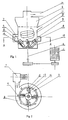
- the reference numerals in the drawings are: 1-motor, 2-shaft, 3-conical plate, 4-hammer plate, 5-grinding chamber, 6-powder selector, 7-air blower, 8-air duct, 9-air vent, 10-outlet, 11-inlet, 12-bottom of grinding chamber, 13-groove, 14-strike-off board, 15-space.
- conical plate 3 is a centrifugal plate which can contain ore materials and rotate about the vertical shaft 2.
- the contour of the plate is an inverted truncated cone. A bottom is fixed at the smaller end of the conical plate.
- the conical plate is in the lower part of the grinding chamber and is mounted on the shaft 2 which is driven by the motor 1.
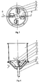
- a powder selector 6 There are an inlet 11 and an outlet 10 of the material, a powder selector 6, an air loop air duct 8(in Fig.1) or a central air duct 8(in Fig.4), a grinding chamber 5 formed between the bottom 12 of the grinding chamber and the powder selector 6, an air blower 7 connected with the air duct 8 and the air vents 9 of the air duct through which the high speed air can go into the grinding chamber.
- hammer plates 4 are uniformly and circumferentially installed on the inner surface of conical plate 3, along the generating line and vertically to the inner surface of the conical plate.
- the hammer plates are detachable.
- powder selector 6 is at the top of cylindrical grinding chamber 5.
- the sieved product is transmitted out through materials outlet 10.
- the cross-section of the air vent 9 is semi-ring-shaped or rectangular, is horizontally round the outside wall of the grinding chamber 5.
- the angle between the center line of an air vent 8 and thee normal line at the point of the circumference of the inner wall of the grinding chamber (at which said center line passes through) is an acute one.
- the angle is preferably 90 degrees, so that the air-flow from air vent 9 approaches the tangent direction of the inner wall of the grinding chamber 5 so that a vortex is generated by means of the function of the inner wall.
- the air vents 9 are uniformly distributed along the circumference of the wall of the cylindrical grinding chamber.
- the number of the air vents is generally 1 to 8, however, the optimal number is 6 to 8.
- Conical plate 3 with hammer plate 4 is in the lower part of the grinding chamber 5 and is mounted on the shaft 2.
- the linear speed of the conical plate at the outer edge of the plate is over 9 m/sec.
- the speed in the emdodiments is 30-50 m/sec.
- curved duct 8 stretches into the grinding chamber 5 from above of the grinding chamber.
- the air vent 9 is located immediately above conical plate 3 and faces it. When air-flow goes into grinding chamber 5 and runs into conical plate 3 with hammer plates 4, the vortex with high speed is generated.
- the working principle of the present invention is as follows: Large pieces of raw materials transmitted into the grinding chamber through the inlet of the materials are firstly crushed by the hammer plates 4 at high speed, the broken materials fly off against the wall of the grinding chamber and are again stricken by the wall (the intermediate and fine grinding are finished).
- the crushed materials are self-ground when they go up spirally in the inner wall of the grinding chamber with high kinetic energy.
- the speed of larger pieces of materials gradually decreases and they separate from the wall and fall under the promotion of the ascending materials from the bottom. They are stricken again and thrown off when they fall down on the surface of conical plate 3. They move in circles until they are ground into small particles.
- the small particles move up spirally along the wall under the driving of the vortex and the fineness is improved.
- the small particles driven by air-flow pass through the powder selector 6 and outlet 10 and finally go into a selecting system.
- this pulverizing apparatus provided in the invention has the function to combine intermediate crushing, fine crushing, grinding, and powder selecting into one whole, so that the processing procedure and the process flow are reduced and simplified.
- the ratio of crushing to grinding is higher.
- the lumpiness of the feed ore is 150mm, the highest can be 250mm.
- the in-feed lumpiness for ball mills and oscillating mills is only 20-40 mm.
- the particle fineness of the product provided by the invention can be 60-325 Meshes (a unit describing size of powder, it implies the hole number square inch area of sifter) and the output is 1-5 tons/hr.
Landscapes
- Engineering & Computer Science (AREA)
- Food Science & Technology (AREA)
- Crushing And Pulverization Processes (AREA)
- Disintegrating Or Milling (AREA)
Claims (8)
- Dispositif pulvérisateur comprenant :une chambre de broyage (5) ayant une entrée de matériau (11);un sélecteur de poudre (6), ayant une sortie de matériau (10), disposé sur ladite chambre et connecté à cette dernière;une soufflante d'air (7) communiquant avec ladite chambre via un conduit d'air (8), ledit conduit d'air comprenant un trou d'évent d'air (9) ménagé au-dessus d'une plaque conique (3) montée tournante dans ladite chambre de broyage, de manière à produire un tourbillon d'air dans ladite chambre, et ayant une position bien plus basse que celle de ladite entrée de matériau, de manière qu'un volume de broyage soit formé au-dessus de la plaque conique, caractérisé en ce queladite plaque conique (3) présente une pluralité d'aubes radiales (4) sur sa surface intérieure et en ce qu'une pluralité de fentes (13) est formée le long de la ligne de production sur ladite plaque conique (3) et un panneau de butée (14) étant fixé dans chaque fente, s'étirant dans l'espace entre ladite plaque conique et le fond de ladite chambre de broyage (5), de manière que les matériaux tombant au-dessous de ladite plaque puisse être prélevés.
- Dispositif pulvérisateur selon la revendication 1, caractérisé en ce que le conduit d'air (8) se trouve autour de ladite chambre de broyage (5) et est connecté à cette dernière via des trous d'évent (9) en un nombre supérieur à un, et en ce que l'angle entre l'axe d'un trou d'évent d'air et la ligne perpendiculaire au point de la circonférence de la paroi intérieure (au niveau duquel passe ledit axe) de ladite chambre de broyage est un angle aigu.
- Dispositif pulvérisateur selon la revendication 2, caractérisé en ce que les trous d'évent d'air sont distribués uniformément le long de la circonférence de la paroi intérieure de ladite chambre de broyage (5).
- Dispositif pulvérisateur selon la revendication 1, caractérisé en ce que le conduit d'air (8) rejoint la chambre de broyage depuis le dessus de la plaque conique (3) et en ce que le trou d'évent d'air (9) se trouve immédiatement au-dessus de la plaque conique et est tournée vers ladite plaque conique.
- Dispositif pulvérisateur selon la revendication 1, caractérisé en ce que la distance entre le trou d'évent d'air (9) et la plaque conique (3) ne dépasse pas un 1/5 de la longueur de ladite chambre de broyage (5).
- Dispositif pulvérisateur selon les revendications 1, 2 ou 3, caractérisé en ce que la vitesse de l'air au niveau du trou d'évent d'air (9) est comprise dans la plage allant de 30 à 50 m/sec.
- Dispositif pulvérisateur selon l'une des revendications 1 à 5, caractérisé en ce que la vitesse linéaire de la plaque conique (3) au niveau du bord extérieur est comprise dans la plage allant de 30 à 50 m/sec.
- Dispositif pulvérisateur selon l'une des revendications 1 à 5, caractérisé en ce que le rapport entre la longueur de la chambre de broyage (5) depuis la surface supérieure de la plaque conique (3), vers l'entrée des matériaux, et le diamètre de la chambre de broyage est supérieur à 1/2.
Applications Claiming Priority (2)
| Application Number | Priority Date | Filing Date | Title |
|---|---|---|---|
| CN92209032U CN2122687U (zh) | 1992-05-03 | 1992-05-03 | 立轴锤破旋风离心自磨机 |
| CN92209032U | 1992-05-03 |
Publications (3)
| Publication Number | Publication Date |
|---|---|
| EP0568941A2 EP0568941A2 (fr) | 1993-11-10 |
| EP0568941A3 EP0568941A3 (fr) | 1993-11-24 |
| EP0568941B1 true EP0568941B1 (fr) | 1996-10-16 |
Family
ID=4954401
Family Applications (1)
| Application Number | Title | Priority Date | Filing Date |
|---|---|---|---|
| EP93107084A Expired - Lifetime EP0568941B1 (fr) | 1992-05-03 | 1993-04-30 | Dispositif pulvérisateur |
Country Status (6)
| Country | Link |
|---|---|
| US (1) | US5542615A (fr) |
| EP (1) | EP0568941B1 (fr) |
| CN (1) | CN2122687U (fr) |
| AU (1) | AU660542B2 (fr) |
| BR (1) | BR9301726A (fr) |
| DE (1) | DE69305413T2 (fr) |
Cited By (2)
| Publication number | Priority date | Publication date | Assignee | Title |
|---|---|---|---|---|
| CN105107602A (zh) * | 2015-09-17 | 2015-12-02 | 湖州新奥特医药化工有限公司 | 一种乙酰丙酮钙粉碎机 |
| US20220032314A1 (en) * | 2020-07-29 | 2022-02-03 | Chester Arthur Clark | Recycling waste refractory material |
Families Citing this family (16)
| Publication number | Priority date | Publication date | Assignee | Title |
|---|---|---|---|---|
| SI9400384A (en) * | 1994-10-07 | 1996-04-30 | Karel Ferlez | Universal mill |
| WO1996014158A1 (fr) * | 1994-11-08 | 1996-05-17 | Guoru Gao | Procede de broyage par tourbillon et son appareil de mise en oeuvre |
| CN1072525C (zh) * | 1995-09-06 | 2001-10-10 | 曹龙 | 固体物料粉磨热交换方法及装置 |
| US5732894A (en) * | 1995-11-09 | 1998-03-31 | Sheahan; Richard T. | Micronization apparatus and method |
| WO2003088204A1 (fr) * | 2002-04-12 | 2003-10-23 | Obermeyer Henry K | Manette a axes multiples et moyen transducteur associe |
| AUPS236102A0 (en) * | 2002-05-16 | 2002-06-13 | Aimbridge Pty Ltd | Grinder |
| CN1295021C (zh) * | 2004-04-15 | 2007-01-17 | 杨富茂 | 机械湍流磨 |
| US20060277887A1 (en) * | 2005-05-31 | 2006-12-14 | Nutragon, Llc | Method for processing organic plant matter into dry powder, oil and juice products |
| CN102861649A (zh) * | 2011-07-09 | 2013-01-09 | 石志训 | 涡旋动能气流制粉机用动能转盘 |
| RU2496581C1 (ru) * | 2012-06-14 | 2013-10-27 | Федеральное государственное бюджетное образовательное учреждение высшего профессионального образования "Южно-Российский государственный университет экономики и сервиса" (ФГБОУ ВПО "ЮРГУЭС") | Мельница |
| RU2520008C1 (ru) * | 2013-02-11 | 2014-06-20 | Федеральное государственное бюджетное образовательное учреждение высшего профессионального образования "Южно-Российский государственный университет экономики и сервиса" (ФГБОУ ВПО "ЮРГУЭС") | Измельчитель динамического самоизмельчения материала |
| CN103252284B (zh) * | 2013-05-17 | 2015-09-30 | 江苏中远机械设备制造有限公司 | 粉体解聚打散机 |
| CN105728147B (zh) * | 2016-03-07 | 2018-05-08 | 钟文虎 | 对撞式气流粉碎机构及粉碎机 |
| CN107242571B (zh) * | 2017-05-17 | 2020-09-08 | 宁波拜尔玛生物科技有限公司 | 基于纳米技术制备的低聚糖及其在肠道健康中的应用 |
| CN109708933B (zh) * | 2018-11-12 | 2021-10-29 | 河南大学 | 一种样品土壤粉碎烘干装置 |
| CN113083113A (zh) * | 2021-02-24 | 2021-07-09 | 深圳云鑫技术有限公司 | 一种光学镀膜材料生产原料混合装置 |
Family Cites Families (13)
| Publication number | Priority date | Publication date | Assignee | Title |
|---|---|---|---|---|
| US3302895A (en) * | 1963-08-26 | 1967-02-07 | Macartney Patents Ltd | Pulverizing apparatus |
| US3348779A (en) * | 1964-10-02 | 1967-10-24 | Norwood H Andrews | Method and apparatus for comminuting materials |
| DE1607562B1 (de) * | 1967-01-17 | 1969-12-18 | Polysius Ag | Schuesselmuehle mit frei beweglichen Mahlkoerpern |
| US4238078A (en) * | 1979-03-22 | 1980-12-09 | Severo-Kavkazsky Gorno-Metallurgichesky Institute | Apparatus for disintegrating a lumped material |
| US4739937A (en) * | 1985-08-19 | 1988-04-26 | Pangborn Corporation | Apparatus for conditioning granular material |
| US4682738A (en) * | 1985-11-20 | 1987-07-28 | Chang Shien F | Grinding mill |
| ES2024560B3 (es) * | 1987-03-24 | 1992-03-01 | Mitsubishi Heavy Ind Ltd | Molino de rodillos. |
| JPH01250487A (ja) * | 1988-03-31 | 1989-10-05 | Satomi Seisakusho:Kk | 紙料精選装置 |
| US4905918A (en) * | 1988-05-27 | 1990-03-06 | Ergon, Inc. | Particle pulverizer apparatus |
| SU1715404A1 (ru) * | 1989-08-07 | 1992-02-28 | Северо-Кавказский горно-металлургический институт | Мельница динамического самоизмельчени |
| JPH0748715Y2 (ja) * | 1989-12-08 | 1995-11-08 | 株式会社サトミ製作所 | 紙料精選装置 |
| DK0510890T3 (da) * | 1991-04-23 | 1995-11-27 | Ecc Int Ltd | Tørformaling |
| US5236133A (en) * | 1991-12-04 | 1993-08-17 | Lundquist Lynn C | Method of container label removal |
-
1992
- 1992-05-03 CN CN92209032U patent/CN2122687U/zh active Granted
-
1993
- 1993-04-30 DE DE69305413T patent/DE69305413T2/de not_active Expired - Fee Related
- 1993-04-30 AU AU38307/93A patent/AU660542B2/en not_active Ceased
- 1993-04-30 EP EP93107084A patent/EP0568941B1/fr not_active Expired - Lifetime
- 1993-05-03 US US08/056,990 patent/US5542615A/en not_active Expired - Fee Related
- 1993-05-03 BR BR9301726A patent/BR9301726A/pt not_active IP Right Cessation
Cited By (2)
| Publication number | Priority date | Publication date | Assignee | Title |
|---|---|---|---|---|
| CN105107602A (zh) * | 2015-09-17 | 2015-12-02 | 湖州新奥特医药化工有限公司 | 一种乙酰丙酮钙粉碎机 |
| US20220032314A1 (en) * | 2020-07-29 | 2022-02-03 | Chester Arthur Clark | Recycling waste refractory material |
Also Published As
| Publication number | Publication date |
|---|---|
| AU660542B2 (en) | 1995-06-29 |
| EP0568941A3 (fr) | 1993-11-24 |
| EP0568941A2 (fr) | 1993-11-10 |
| CN2122687U (zh) | 1992-11-25 |
| DE69305413T2 (de) | 1997-03-13 |
| BR9301726A (pt) | 1993-11-09 |
| DE69305413D1 (de) | 1996-11-21 |
| AU3830793A (en) | 1993-11-04 |
| US5542615A (en) | 1996-08-06 |
Similar Documents
| Publication | Publication Date | Title |
|---|---|---|
| EP0568941B1 (fr) | Dispositif pulvérisateur | |
| JP3139721B2 (ja) | 流動化ベッドジェットミル | |
| US5850977A (en) | Method and apparatus for comminuting solid particles | |
| US5732894A (en) | Micronization apparatus and method | |
| US5826807A (en) | Method and apparatus for comminuting of solid particles | |
| EP0507983B1 (fr) | Pulvérisateur pourvu d'un anneau d'étranglement rotatif | |
| US2304264A (en) | Apparatus for pulverizing and classifying materials | |
| CZ232096A3 (en) | Device with counter-rotating rotors for coal/mineral pulverizer | |
| US4228964A (en) | Apparatus for processing cellulose insulation | |
| CN109499870A (zh) | 内循环可控的扁平型静态选粉机、系统及工艺流程 | |
| JPH0767541B2 (ja) | 水平旋回流型ジェットミル | |
| JPS6136463B2 (fr) | ||
| JPS6136459B2 (fr) | ||
| JPH02265660A (ja) | 遠心流動粉砕装置 | |
| KR102352635B1 (ko) | 고형소재를 위한 분쇄장치 | |
| JPS6366582B2 (fr) | ||
| JP2000015127A (ja) | 複数の加速ノズルを備えた気流式粉砕機、及びトナーの製造方法 | |
| SU1079289A2 (ru) | Сепарационное устройство струйной мельницы | |
| KR0167010B1 (ko) | 압축성 유체를 이용한 미분체의 분쇄 방법 및 그 장치 | |
| JPH06277554A (ja) | 微粒化装置 | |
| CN115672511A (zh) | 一种根茎类中药超微粉碎系统 | |
| JP2544246B2 (ja) | 遠心流動粉砕装置 | |
| JPS5916497B2 (ja) | 竪型微粉砕機 | |
| JPS6366581B2 (fr) | ||
| JPS6499B2 (fr) |
Legal Events
| Date | Code | Title | Description |
|---|---|---|---|
| PUAI | Public reference made under article 153(3) epc to a published international application that has entered the european phase |
Free format text: ORIGINAL CODE: 0009012 |
|
| PUAL | Search report despatched |
Free format text: ORIGINAL CODE: 0009013 |
|
| AK | Designated contracting states |
Kind code of ref document: A2 Designated state(s): DE FR GB |
|
| AK | Designated contracting states |
Kind code of ref document: A3 Designated state(s): DE FR GB |
|
| 17P | Request for examination filed |
Effective date: 19940218 |
|
| 17Q | First examination report despatched |
Effective date: 19950620 |
|
| GRAG | Despatch of communication of intention to grant |
Free format text: ORIGINAL CODE: EPIDOS AGRA |
|
| GRAH | Despatch of communication of intention to grant a patent |
Free format text: ORIGINAL CODE: EPIDOS IGRA |
|
| GRAH | Despatch of communication of intention to grant a patent |
Free format text: ORIGINAL CODE: EPIDOS IGRA |
|
| GRAA | (expected) grant |
Free format text: ORIGINAL CODE: 0009210 |
|
| AK | Designated contracting states |
Kind code of ref document: B1 Designated state(s): DE FR GB |
|
| ET | Fr: translation filed | ||
| REF | Corresponds to: |
Ref document number: 69305413 Country of ref document: DE Date of ref document: 19961121 |
|
| PLBE | No opposition filed within time limit |
Free format text: ORIGINAL CODE: 0009261 |
|
| STAA | Information on the status of an ep patent application or granted ep patent |
Free format text: STATUS: NO OPPOSITION FILED WITHIN TIME LIMIT |
|
| 26N | No opposition filed | ||
| PGFP | Annual fee paid to national office [announced via postgrant information from national office to epo] |
Ref country code: FR Payment date: 19980330 Year of fee payment: 6 |
|
| PGFP | Annual fee paid to national office [announced via postgrant information from national office to epo] |
Ref country code: GB Payment date: 19980421 Year of fee payment: 6 |
|
| PGFP | Annual fee paid to national office [announced via postgrant information from national office to epo] |
Ref country code: DE Payment date: 19980624 Year of fee payment: 6 |
|
| PG25 | Lapsed in a contracting state [announced via postgrant information from national office to epo] |
Ref country code: GB Free format text: LAPSE BECAUSE OF NON-PAYMENT OF DUE FEES Effective date: 19990430 |
|
| GBPC | Gb: european patent ceased through non-payment of renewal fee |
Effective date: 19990430 |
|
| PG25 | Lapsed in a contracting state [announced via postgrant information from national office to epo] |
Ref country code: FR Free format text: LAPSE BECAUSE OF NON-PAYMENT OF DUE FEES Effective date: 19991231 |
|
| REG | Reference to a national code |
Ref country code: FR Ref legal event code: ST |
|
| PG25 | Lapsed in a contracting state [announced via postgrant information from national office to epo] |
Ref country code: DE Free format text: LAPSE BECAUSE OF NON-PAYMENT OF DUE FEES Effective date: 20000201 |