EP0568070B1 - Homogenisierungssystem mit einem verbessertem Strömungsweg - Google Patents
Homogenisierungssystem mit einem verbessertem Strömungsweg Download PDFInfo
- Publication number
- EP0568070B1 EP0568070B1 EP93106977A EP93106977A EP0568070B1 EP 0568070 B1 EP0568070 B1 EP 0568070B1 EP 93106977 A EP93106977 A EP 93106977A EP 93106977 A EP93106977 A EP 93106977A EP 0568070 B1 EP0568070 B1 EP 0568070B1
- Authority
- EP
- European Patent Office
- Prior art keywords
- valve
- seal
- bore
- pump
- block
- Prior art date
- Legal status (The legal status is an assumption and is not a legal conclusion. Google has not performed a legal analysis and makes no representation as to the accuracy of the status listed.)
- Revoked
Links
Images


Classifications
-
- B—PERFORMING OPERATIONS; TRANSPORTING
- B01—PHYSICAL OR CHEMICAL PROCESSES OR APPARATUS IN GENERAL
- B01F—MIXING, e.g. DISSOLVING, EMULSIFYING OR DISPERSING
- B01F25/00—Flow mixers; Mixers for falling materials, e.g. solid particles
- B01F25/60—Pump mixers, i.e. mixing within a pump
-
- B—PERFORMING OPERATIONS; TRANSPORTING
- B01—PHYSICAL OR CHEMICAL PROCESSES OR APPARATUS IN GENERAL
- B01F—MIXING, e.g. DISSOLVING, EMULSIFYING OR DISPERSING
- B01F25/00—Flow mixers; Mixers for falling materials, e.g. solid particles
- B01F25/40—Static mixers
- B01F25/44—Mixers in which the components are pressed through slits
- B01F25/441—Mixers in which the components are pressed through slits characterised by the configuration of the surfaces forming the slits
- B01F25/4412—Mixers in which the components are pressed through slits characterised by the configuration of the surfaces forming the slits the slits being formed between opposed planar surfaces, e.g. pushed again each other by springs
-
- B—PERFORMING OPERATIONS; TRANSPORTING
- B01—PHYSICAL OR CHEMICAL PROCESSES OR APPARATUS IN GENERAL
- B01F—MIXING, e.g. DISSOLVING, EMULSIFYING OR DISPERSING
- B01F25/00—Flow mixers; Mixers for falling materials, e.g. solid particles
- B01F25/40—Static mixers
- B01F25/44—Mixers in which the components are pressed through slits
- B01F25/442—Mixers in which the components are pressed through slits characterised by the relative position of the surfaces during operation
- B01F25/4422—Mixers in which the components are pressed through slits characterised by the relative position of the surfaces during operation the surfaces being maintained in a fixed but adjustable position, spaced from each other, therefore allowing the slit spacing to be varied
-
- B—PERFORMING OPERATIONS; TRANSPORTING
- B01—PHYSICAL OR CHEMICAL PROCESSES OR APPARATUS IN GENERAL
- B01F—MIXING, e.g. DISSOLVING, EMULSIFYING OR DISPERSING
- B01F35/00—Accessories for mixers; Auxiliary operations or auxiliary devices; Parts or details of general application
- B01F35/71—Feed mechanisms
-
- B—PERFORMING OPERATIONS; TRANSPORTING
- B01—PHYSICAL OR CHEMICAL PROCESSES OR APPARATUS IN GENERAL
- B01F—MIXING, e.g. DISSOLVING, EMULSIFYING OR DISPERSING
- B01F35/00—Accessories for mixers; Auxiliary operations or auxiliary devices; Parts or details of general application
- B01F35/71—Feed mechanisms
- B01F35/712—Feed mechanisms for feeding fluids
-
- B—PERFORMING OPERATIONS; TRANSPORTING
- B01—PHYSICAL OR CHEMICAL PROCESSES OR APPARATUS IN GENERAL
- B01F—MIXING, e.g. DISSOLVING, EMULSIFYING OR DISPERSING
- B01F35/00—Accessories for mixers; Auxiliary operations or auxiliary devices; Parts or details of general application
- B01F35/71—Feed mechanisms
- B01F35/717—Feed mechanisms characterised by the means for feeding the components to the mixer
- B01F35/7174—Feed mechanisms characterised by the means for feeding the components to the mixer using pistons, plungers or syringes
-
- B—PERFORMING OPERATIONS; TRANSPORTING
- B01—PHYSICAL OR CHEMICAL PROCESSES OR APPARATUS IN GENERAL
- B01F—MIXING, e.g. DISSOLVING, EMULSIFYING OR DISPERSING
- B01F35/00—Accessories for mixers; Auxiliary operations or auxiliary devices; Parts or details of general application
- B01F35/71—Feed mechanisms
- B01F35/717—Feed mechanisms characterised by the means for feeding the components to the mixer
- B01F35/7176—Feed mechanisms characterised by the means for feeding the components to the mixer using pumps
- B01F35/717613—Piston pumps
-
- B—PERFORMING OPERATIONS; TRANSPORTING
- B01—PHYSICAL OR CHEMICAL PROCESSES OR APPARATUS IN GENERAL
- B01F—MIXING, e.g. DISSOLVING, EMULSIFYING OR DISPERSING
- B01F35/00—Accessories for mixers; Auxiliary operations or auxiliary devices; Parts or details of general application
- B01F35/75—Discharge mechanisms
- B01F35/754—Discharge mechanisms characterised by the means for discharging the components from the mixer
- B01F35/7547—Discharge mechanisms characterised by the means for discharging the components from the mixer using valves, gates, orifices or openings
-
- B—PERFORMING OPERATIONS; TRANSPORTING
- B01—PHYSICAL OR CHEMICAL PROCESSES OR APPARATUS IN GENERAL
- B01F—MIXING, e.g. DISSOLVING, EMULSIFYING OR DISPERSING
- B01F35/00—Accessories for mixers; Auxiliary operations or auxiliary devices; Parts or details of general application
- B01F35/30—Driving arrangements; Transmissions; Couplings; Brakes
- B01F2035/35—Use of other general mechanical engineering elements in mixing devices
- B01F2035/351—Sealings
Definitions
- the invention relates to a homogenizer comprising a pump and a homogenizing valve, the pump including a pump block with a bore formed in the pump block, a fluid flow path of the pump passing through the bore, and a retaining member located at an end of the bore for closing the end of the bore.
- Homogenization is the breaking down and mixing of the components of an emulsion or dispersion.
- a major use of homogenizers is to break down and disperse milk fat into the bulk of skim milk. This delays creaming of milk fat globules.
- Homogenizers are also used to process other emulsions such as silicon oil and to process dispersions such as pigments, antacids and various paper coatings.
- the emulsion is introduced at high pressure of from 3,448 kPa to 68,960 kPa to a central bore within an annular valve seat.
- the emulsion is forced out through a narrow gap between the valve seat and a valve member. Through the gap, the emulsion undergoes extremely rapid acceleration as well as an extreme drop in pressure. This violent action through the valve breaks down globules within the emulsion to produce the homogenized product.
- the degree of homogenization is a function of the difference between the pressure of the emulsion at the inlet of the valve and the pressure at the outlet.
- homogenizers have not typically been required to operate at pressures of greater than 68,960 KPa.
- recent applications such as cell disruption have required significantly higher pressures of about 103,440 kPa or more.
- a typical homogenizer system includes a homogenizer valve mounted to the side of a pump block.
- the pump is a plunger pump having multiple plungers which draw fluid from a common suction manifold and discharge it into a common discharge manifold delivering high pressure fluid to the homogenizer valve.
- the suction and discharge manifolds are cross bores which extend parallel to opposite faces of the block. Valve bores drilled through one of those faces join the two manifolds, and a valve assembly is positioned at each end of each of those valve bores. Another set of bores is drilled through an adjacent face of the block to form pump chambers which house the plungers. Each pump chamber intersects each valve bore at a 90 degrees angel.
- Each plunger reciprocates in a pump chamber to draw fluid through a suction valve from the suction manifold and force the fluid through the discharge valve into the discharge manifold which is connected to the homogenizer valve.
- the homogenizer has a primary fluid flow path extending from the suction manifold and through the suction valves, the pump chambers, the discharge manifold and the homogenizer valve.
- a desired homogenizing pressure is maintained by adjusting the gap between the valve member and the valve seat.
- that adjustment is made by an actuator assembly which may be a spring-loaded handwheel or a hydraulic or pneumatic actuator system.
- the hydraulic or pneumatic system provides for regulating of the process via a control panel, eliminating the need for manual adjustments.
- FR-A-1 339 362 discloses a seal arrangement in a homogenizing pump for sealing between a pump piston and a pump chamber where a compression spring retains a series of seals positioned adjacent to each other.
- FR-A-1 339 362 describes an arrangement for sealing a reciprocating piston within a bore, which is similar to that of US-A-2 901 981, except that the sealing components are pressed against each other by a compression spring which serves as a retaining member.
- Document FR-A-1 339 362 also discloses a channel for admitting steam during the operation for destroying germs carried within the pump by the reciprocation of the piston.
- a homogenizer of the type mentioned in the beginning which is characterized by a seal located along the fluid flow path on a radial step in the bore adjacent to an axially directed peripheral ridge of the retaining member, the seal being flush with the bore and an inner surface of the ridge.
- Homogenizing systems used for food processing are typically subjected to a daily cleaning procedure in which the primary fluid flow path is flushed with cleaning fluids. More specifically, the primary flow path is initially flushed with an acid solution, followed by a neutralizing agent for neutralizing the acid. Next, the flow path is flushed with water, followed by a chlorine solution for sanitization. Although this flushing procedure effectively removes residue which collects along smooth areas of the primary flow path, it is not very effective in removing residue buildup in crevices, stagnant areas, corners and mating surfaces along the flow path which are caused mainly by recessed seals. As such, homogenizing systems require a disassembly cleaning procedure or a frequent high-intensity in-line cleaning to remove residue buildup along the primary flow path.
- a goal of the present invention is to reduce costs for cleaning and sanitizing of a homogenizing system by decreasing:
- a homogenizer in one embodiment, includes a homogenizing valve mounted to a pump block.
- a set of one or more pump chambers is formed in the block.
- Suction valves and discharge valves are positioned in respective suction valve bores and discharge valve bores.
- the valve bores are formed in the block and are in communication with the set of pump chambers.
- a primary fluid flow path extends through the suction valves, the suction valve bores, the pump chambers, the discharge valve bores, the discharge valves and the homogenizing valve.
- the homogenizer comprises exposed seals positioned along the primary flow path to have a surface which is flush with the fluid flow path.
- the exposed seals are employed along the primary flow path in the pump chambers, the discharge valve bores and the homogenizing valve such that the buildup of residue is minimized, the growth of microorganisms is slowed and a proper contact between cleaning agents and sealing area is achieved.
- the homogenizing pump has an internal geometry with substantially all cracks, crevices and stagnant areas eliminated.
- an exposed seal is positioned in a radial step formed at the end of a pump bore through which fluid passes.
- the exposed seal is secured in the radial step by an axially directed peripheral ridge of a retaining member which is mounted to the pump closing the end of the bore.
- the seal is flush with the pump bore and an inner surface of the ridge. As such, a surface of the seal is directly exposed to the fluid flow path thereby minimizing fluid residue buildup and microorganism growth.
- an exposed seal is positioned in a radial step formed in the end of each pump chamber and secured by an axially directed peripheral ridge of a retainer closing the pump chamber.
- the seal is flush with the pump chamber and an inner surface of the ridge and has a surface directly exposed to the fluid flow path.
- Another exposed seal is positioned on a radial step formed in each discharge valve bore and secured by the discharge valve assembly. The seal is flush with the discharge valve bore and inner surface of an axially directed peripheral ridge of the discharge valve assembly such that a surface of the seal is exposed to the fluid flow path.
- the pump block is coupled to a homogenizer valve assembly comprising a valve seat with central bore into which fluid from the discharge manifold enters.
- a valve member within a valve body is spaced adjacent to the valve seat to provide a gap through which fluid is expressed.
- An impact ring surrounds the gap for directing the fluid into a peripheral chamber or region.
- the impact ring is shrink fitted about the valve member, providing a zero clearance crevice between the impact ring and valve member. As such, microorganism growth in the crevice is slowed and fluid residue buildup is minimized.
- the homogenizing valve assembly further comprises an actuator assembly having a shaft for actuating the valve member to adjust the gap.
- an exposed dynamic seal is coupled to the valve body and to the shaft adjacent to the peripheral region.
- the dynamic seal is preferably an elastomer seal which flexes as the shaft is translated.
- a flow through high pressure gauge assembly is mounted to the pump block for measuring outlet (or inlet) pressures.
- a flow-through type of pressure gauge is used because it has no dead space along its flow channel.
- the pressure gauge assembly has a flow channel comprising a pair of exposed seals, wherein each seal is located on a radial step at an end of the flow channel. The seals are flush with the flow channel and the primary flow path of the pump.
- the pressure gauge assembly is mounted between the pump block and the homogenizing valve assembly. The pressure gauge assembly is axially clamped to the pump block, thereby securing the one exposed seal against the block and the other exposed seal against the homogenizing valve assembly.
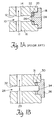
- FIG. 1A is a partial cross-sectional view of primary fluid flow path of a prior art homogenizing system.
- FIG. 1B is a partial cross-sectional view of a primary fluid flow path of a homogenizing system of the present invention.
- FIG. 2 is a perspective view of a homogenizer valve and pump assembly embodying the present invention.
- FIG. 3 is a cross-sectional view of the pump of FIG. 2 taken along line 2-2.
- FIG. 4 is a elevational view, partially broken away, of the system FIG. 2 as viewed from the rear of FIG. 2.
- FIG. 5 is a cross-sectional view of the homogenizer valve and actuator valve assembly of the system of FIG. 2.
- Homogenizing systems are subjected to a daily cleaning procedure wherein the primary fluid flow path is flushed with cleaning fluids.
- this procedure is not completely effective in removing residue buildup in crevices, cul-de-sacs, dead-ends, tight internal radius areas, stagnant areas, corners and mating surfaces along the flow path caused by recessed seals.
- FIG. 1A a section of a primary fluid flow path 11 of a prior art homogenizing system is shown in FIG. 1A.
- the flow path 11 intersects a bore 10 formed in a conduit 12 defined by a first structure 14 and a second structure 16.
- An end of the bore 10 is closed by a cap 18.
- a recessed seal 20 is located in a step 22 in the bore 10 adjacent to the cap 18, creating a crevice 24 and corners 26 at which residue buildup occurs or microorganisms can survive.
- FIG. 1A The structure of present FIG. 1A is similar to the structure of FIG. 2 of US-A-2 901 981 insofar as the latter shows a homogenizer according to the preamble of present claim 1 wherein, however, the retaining member 24 of FIG. 2 of US-A-2 901 981 does not fully close the bore 16 contrary to the retaining member 18 of present FIG. 1A.
- the homogenizer internal geometry is configured such that exposed seals may be positioned along the primary flow path to have a surface flush with the flow path and exposed directly to the flow path for minimizing residue buildup and microorganism growth along the flow path.
- a homogenizer embodying the present invention can operate for an extended period before a cleaning procedure is required.
- FIG. 1B illustrates a section of the primary flow path 29 of a homogenizing system embodying the basic principle of the present invention.
- the flow path 29 intersects a bore 28 formed in a conduit 32.
- An exposed seal 30 is positioned on a radial step 31 of the bore 28 adjacent to an axially directed peripheral ridge 34 of a cap 36.
- a surface of the seal 30 is directly exposed to the primary flow path 29, while the remaining three surfaces are fully sealed.
- the crevice and the corners as well as potential (see FIG. 1A) residue buildup in those areas are eliminated.
- FIG. 2 is a perspective view of a homogenizer system embodying the present invention. The view is from a direction which a user would consider to be the rear of the system to show the plunger drive.
- a homogenizer valve assembly 40 is mounted to a pump block 42. The valve assembly receives pressurized fluid from the pump, and the homogenized fluid is discharged through a flanged port 44 (also see FIG. 5). Pressure of the fluid entering the homogenizer system can be monitored by a high pressure gauge (not shown), and pressure of the fluid entering the homogenizer valve assembly 40 can be monitored by a high pressure gauge 46 mounted to the block 42.
- the pump comprises three plunger pumps which operate, in parallel, 120° out of phase with each other.
- a plunger 48, 50 and 52 is coupled to a respective drive shaft 54, 56, and 58 by means of a compression coupling 60, 62 and 64.
- the drive shafts are driven through an eccentric shaft 65 located in box 66 by an electric motor (not shown).
- a set of three suction valves are located along the bottom of the block 42, and a set of three discharge valves are located along the top of the block and may be accessed by removal of top caps 68.
- fluid is drawn into the pump 42 through a flanged port 70 into a manifold 72.
- the pressure gauge 73 is coupled to the manifold 72 and provides an indication of the inlet fluid pressure.
- the manifold 72 is a cross-bore extending through the block parallel to the bottom face 74 without dead ends.
- the manifold extends through a set of three parallel suction valve bores 76. One of these valve bores is illustrated in FIG 3.
- a suction valve assembly 78 is positioned in each bore.
- the suction valve 78 communicates with a pump chamber 80 through the suction valve bore 76.
- the plunger 52 drives fluid from the pump chamber 80 through a discharge valve bore 82 to a discharge valve assembly 84.
- the discharge valve assembly 84 is positioned in the bore 82 which communicates with a discharge manifold 86 without dead ends.
- the discharge manifold 86 is also a cross-bore and is parallel to the upper face 88 of the block 42.
- any number of plunger pumps capable of providing a relatively constant flow rate fluid to the homogenizing valve 40 may be employed without departing from the scope of the present invention.
- the fluid from the three discharge valves 84 is directed by the manifold 88 to the homogenizing valve assembly 40.
- the fluid is introduced into a first stage homogenizing valve 90 for homogenization.
- the homogenized fluid is directed from the first stage valve 90 to a discharge port 92.
- An elbow conduit 94 directs the homogenized fluid to a second stage homogenizing valve 96 for further homogenization.
- the second valve 96 functions identically to the first valve 90 except at a different pressure gradient.
- the final homogenized product exits the second valve 96 through the discharge port 44.
- the pump 42 is a constant volume pump, and pressure is maintained by adjusting the two homogenizing valves 90 and 96. Those adjustments are made by a pair of hydraulic (or pneumatic) actuators 97 and 98 which are described in detail below.
- a plurality of exposed seals are positioned along the primary flow path of the homogenizer. These exposed seals are located in the pump chambers, the discharge valve bores, the pressure gauge blocks and the homogenizing valve as described in detail below.
- the high pressure gauge 73 is mounted to the flanged port 70 to monitor the pressure of fluid entering at the suction manifold 72.
- the gauge 73 is a flow-through diaphragm tube type of pressure gauge (described below) useful for high pressure applications. Fluid entering from the port 70 flows through the gauge 73 and enters the suction manifold 72. A pair of exposed seals 100 and 102 are positioned along flow path of the pressure gauge 73. A nut 103 is employed for axially clamping the pressure gauge 73 to the pump block 42, thereby securing the seal 102 against the block.
- valve assembly 78 positioned in the bore 76 comprises a valve seat 77 having a central channel 79 in communication with the suction manifold.
- a valve member 81 provides fluid communication from the channel 79 to the pump chamber 80 and closes the channel 79 when positive back pressure is applied. Further, the valve member 81 has a member 83 which serves as a guide.
- the pump chamber 80 is formed in the block 42 parallel to the upper and lower faces (88 and 74) of the block.
- the plunger 52 is driven in a bearing 85 in which a fluid or steam is passed through an annulus 87 from a port 89 to a discharge port 91 either for flushing microorganisms to the drain or for simply inactivating them.
- a pair of seals 105a and 105b formed of packing are positioned adjacent to a ring 106 and maintain a dynamic seal.
- One of the packing seals 105b rests against the pump block in the pump chamber and is pressed against the ring 106 by a retainer 112 as the end 110 is bolted onto the block 42.
- the retainer 112 has fingers 113 extending from a cap 114 pressing against the exposed surface of the packing seal 105b.
- the fingers 113 are sufficiently small so that the area adjacent to the exposed packing surface does not become a source of fluid residue build up.
- the retainer 112 also has a ring 116 attached to the fingers 113 for stabilization thereof.
- the ring 116 has a ridge 118 along its periphery which serves as a valve stop for the suction valve 78.
- the retainer 112 is positioned against an exposed seal 120 located in a radial step 121 formed in the pump chamber 80.
- an axially extending peripheral ridge 122 of the cap is pressed against the seal 120.
- the seal 120 is flush with the pump chamber 80 and an inner surface of the ridge 122 such that a surface of the seal is directly exposed to the fluid flow path.
- the base of the ridge has a concave shape to avoid a debris collecting corner.
- the plunger 52 drives fluid from the pump chamber 80 to the discharge valve bore 82.
- the discharge valve assembly 84 positioned in the bore 82 comprises a valve seat 124 having a central channel 126 in communication with a plenum 128 and the discharge manifold 86.
- a valve member 130 is positioned in the channel 126 to provide fluid communication with the plenum 128 and has a member 132 which serves as a guide.
- a top cap 68 has a nose portion 134 which serves as a valve stop for the valve 84. The nose 134 is positioned adjacent to an exposed seal 136 located in a radial step 138 formed the bore 82.
- fluid from the discharge valves is directed by the manifold 86 through a pressure gauge 46 to the homogenizer valve assembly 40.
- the high pressure gauge is mounted to the pump block for monitoring the pressure of fluid entering the homogenizer valve assembly 40.
- the gauge 46 is a flow-through diaphragm tube type pressure gauge useful for high pressure monitoring.
- the gauge 46 has an internal geometry which minimizes residue buildup and microorganism growth along its flow channel.
- fluid exiting the pump 42 passes through the flow channel 147 created by the tube diaphragm 145.
- the tube diaphragm 145 is a thin-walled annular membrane that is welded (at 148) to the gauge block 150 along the flow channel 147.
- the membrane 145 is welded such that it is flush with the gauge block 150 along the flow channel 147. Pressurized fluid passing through the flow channel 147 pushes against the diaphragm causing it to be displaced. The displacement of the diaphragm changes the volume of the liquid region 152 which, in turn, changes the reading of the pressure gauge indicator 154.
- a pair of exposed seals 142 and 144 employed in the pressure gauge 46 have a surface exposed to the fluid flow path. Each seal is positioned on a respective radial step along the flow channel of the gauge 46 such that it is flush with the fluid flow path and the flow channel.
- a nut 146 is employed for axially clamping the gauge to the pump block to secure the seal 142 against the pump block and the seal 144 against the homogenizing valve assembly.
- An exposed seal such as the seal 142 is constructed as follows. An edge 143 of the seal perpendicular to the exposed edge is given a calculated angle for ensuring a defined compression of the sealing lip close to the fluid flow path. As such, no microorganisms can be trapped under the three non-exposed surfaces of the seal 142.
- centering pins 104 are employed to prevent the occurrence of a step (not shown) along the fluid flow path of adjacent parts (42 and 46) sealed by the exposed seal 142. This step would cause a second side 143 of the seal to be exposed, creating a corner capable of fluid residue buildup or microorganism growth.
- the pressurized fluid passes through the pressure gauge and is introduced to the homogenizing valve assembly 40.
- the homogenizing valve assembly 40 is a two-stage unit having the first stage homogenizing valve 90 in series with the second stage homogenizing valve 96.
- a two-stage Hydraulic Valve Actuator (HVA) assembly comprises actuators 97 and 98 which are employed to control the process pressure associated with the first and second stage valves 90 and 96 respectively.
- Pressurized fluid is introduced into the first stage valve 202 through a central bore 200 in an annular valve seat 202.
- the fluid is directed from the bore 200 radially outward through a gap 204 formed between the valve seat 202 and a valve member 206.
- An impact ring 208 surrounds the gap 204 and directs the homogenized fluid to channel 210 formed between the ring 208 and the valve seat 202.
- the impact ring 208 and the valve member 206 are constructed as a shrink fit assembly to avoid crevices and dead space.
- the impact ring 208 and valve member 206 may be a single piece assembly without departing from the scope of the present invention.
- the homogenized fluid travels through the channel 210 to port 212, a plenum 213 and the discharge port 214.
- Seal 216 is positioned adjacent to the channel 210 between the valve seat 202 and the first stage valve body 218. The seal 216 is flush with the valve seat 202 and the valve body 218 such that a surface of the seal 216 is directly exposed to the fluid flow path.
- the homogenizing pressure for the first stage valve 90 is maintained by adjusting the gap 204 using the actuator 90.
- high pressure hydraulic fluid or pneumatic force
- the member 224 is forced downwardly against the valve member 206 closing the gap 204. If on the other hand, the hydraulic pressure is reduced, the valve member 206 is able to move away from the valve seat 202 to increase the gap 204.
- An exposed elastomer seal 226 partially defines the plenum 213 and thus has a surface exposed to the fluid flow path.
- One end of the seal 226 is cemented to and clamped against the valve body 218 and the other end is cemented to the rod 222 and member 224. As the rod 222 is translated to adjust the gap 204, the seal 226 flexes to provide a dynamic seal within the plenum 212.
- the homogenized fluid is directed from the port 92 through an elbow conduit 94 to the second stage homogenizing valve 96.
- An exposed seal 255 is positioned in a notch in the first stage valve 90 adjacent to the elbow conduit 94.
- a surface of the seal 255 is exposed to the fluid flow path to minimize fluid residue buildup at the valve/conduit interface.
- Another seal 244 is located in the elbow conduit 94 and has a surface exposed to the fluid flow path.
- the seal 244 is positioned in a notch in the elbow conduit 94 adjacent to the second stage valve 96.
- the second stage valve 96 serves two important functions. By establishing controlled back pressure, the second stage valve concentrates the energy of the first stage homogenizing zone to ensure maximum efficiency.
- the second stage valve 96 performs further homogenization on the fluid, and the final product is directed from the valve 96 through the discharge port 44. Upside-down mounting of the homogenizing valve assembly assures self-draining performance.
Landscapes
- Chemical & Material Sciences (AREA)
- Chemical Kinetics & Catalysis (AREA)
- Dispersion Chemistry (AREA)
- Details Of Reciprocating Pumps (AREA)
Claims (8)
- Homogenisierer, umfassend eine Pumpe und ein Homogenisierungsventil, wobei die Pumpe einen Pumpenblock (42) mit einer in dem Pumpenblock ausgebildeten Bohrung (80 oder 82) sowie einem durch die Bohrung hindurchgehenden Fluidströmungsweg der Pumpe und ein an einem Ende der Bohrung befindliches Halteteil (112 oder 68) zum Schließen des Endes der Bohrung aufweist, gekennzeichnet durch eine Dichtung (120 oder 136), die sich längs des Fluidströmungswegs auf einer Radialstufe (121 oder 128) in der Bohrung benachbart einer axial gerichteten Umfangsrippe (122 oder 140) des Halteteils befindet, wobei die Dichtung bündig mit der Bohrung und einer inneren Oberfläche der Rippe ist.
- Homogenisierer nach Anspruch 1, dadurch gekennzeichnet, daß die Bohrung (80) eine in dem Pumpenblock (42) ausgebildete Pumpenkammer ist.
- Homogenisierer nach Anspruch 1, dadurch gekennzeichnet, daß die Bohrung (82) eine Entladungsventilbohrung ist, die in dem Pumpenblock (42) ausgebildet und mit einer Pumpenkammer (80) verbunden ist, und das Halteteil eine Entladungsventilanordnung (84) ist, die an einem Ende der Entladungsventilbohrung positioniert ist.
- Homogenisierer nach Anspruch 1, 2 oder 3, dadurch gekennzeichnet, daß er weiter eine Durchflußdruckmeßinstrumentanordnung (46 oder 74) umfaßt, die an dem Pumpenblock (42) angebracht ist und einen Fluidströmungskanal in Verbindung mit dem Fluidströmungsweg der Pumpe hat, wobei die Druckmeßinstrumentanordnung eine sich auf einer Radialstufe längs des Fluidströmungskanals der Druckmeßinstrumentanordnung befindliche Dichtung (102 oder 142) umfaßt, wobei die Dichtung bündig mit dem Fluidströmungsweg und dem Fluidströmungskanal ist, wobei die Druckmeßinstrumentanordnung zum Befestigen der Dichtung gegen den Pumpenblock axial an dem Pumpenblock befestigt ist.
- Homogenisierer nach irgendeinem der vorhergehenden Ansprüche, dadurch gekennzeichnet, daß er weiter folgendes umfaßt:eine Pumpenkammer (80), die durch den Pumpenblock (42) ausgebildet ist und eine Dichtung (120) umfaßt, welche sich längs eines Fluidströmungswegs des Homogenisierers auf einer Radialstufe (121) innerhalb der Pumpenkammer benachbart einer axial gerichteten Umfangsrippe (122) eines Halteteils (112) befindet, das an dem Ende der Kammer positioniert ist, wobei die Dichtung bündig mit der Pumpenkammer und einer inneren Oberfläche der Rippe ist;eine Saugventilanordnung (78), die mit der Pumpenkammer verbunden ist;eine Saugventilbohrung (76), welche die Saugventilanordnung aufnimmt und die Saugventilanordnung mit der Pumpenkammer verbindet;eine Entladungsventilanordnung (84), die mit der Pumpenkammer verbunden ist;eine Entladungsventilbohrung (82), welche die Entladungsventilanordnung aufnimmt und die Entladungsventilanordnung mit der Pumpenkammer verbindet, wobei die Entladungsventilbohrung eine Dichtung (136) umfaßt, die sich auf bzw. in dem Fluidströmungsweg des Homogenisierers auf einer Radialstufe (138) innerhalb der Entladungsventilbohrung benachbart einer axial gerichteten Umfangsrippe (140) der Entladungsventilanordnung befindet, wobei die Dichtung bündig mit der Entladungsventilbohrung und einer inneren Oberfläche der Rippe ist; undeine Homogenisierungsventilanordnung (40), die mit dem Pumpenblock verbunden und in Verbindung mit der Entladungsbohrung ist.
- Homogenisierer nach irgendeinem der vorhergehenden Ansprüche, dadurch gekennzeichnet, daß das Homogenisierungsventil (90) folgendes umfaßt:einen Ventilkörper;einen Ventilsitz (202) innerhalb des Ventilkörpers;ein Ventilteil (206) innerhalb des Ventilkörpers, beabstandet benachbart dem Ventilsitz, um einen Spalt (204) vorzusehen, durch welchen das Fluid ausgedrückt wird, undeinen Stoßring (208), der den Spalt zum Richten bzw. Leiten des ausgedrückten Fluids in einen Umfangsbereich (213) umgibt, wobei der Stoßring im Schrumpfsitz an einer axial gerichteten Oberfläche des Ventilteils angebracht ist.
- Homogenisierer nach Anspruch 6, dadurch gekennzeichnet, daß das Homogenisierungsventil (90) folgendes umfaßt:eine Betätigungsanordnung (97), die eine Betätigungsstange (222) für das Betätigen des Ventilteils (206) zum Einstellen des Spalts (204) hat; undeine dynamische Dichtung (226), die sich benachbart dem Umfangsbereich (213) befindet und mit dem Ventilkörper und der Betätigungsstange (222) verbunden ist, wobei sich die dynamische Dichtung biegt, wenn die Stange parallelverschoben wird.
- Homogenisierer nach irgendeinem der vorherigen Ansprüche, dadurch gekennzeichnet, daß er weiter folgendes umfaßt:einen Satz von Pumpenkammern (80), die durch eine erste Oberfläche des Blocks (42) ausgebildet sind;eine Dichtung (120), die in jeder Pumpenkammer längs eines Fluidströmungswegs des Homogenisierers positioniert ist, wobei sich jede Dichtung auf einer Radialstufe (121) innerhalb der jeweiligen Pumpenkammer benachbart einer axial gerichteten Umfangsrippe (122) eines jeweiligen Halteteils (112), das an einem Ende des Blocks angebracht ist, befindet, wobei die Dichtung bündig mit der Pumpenkammer und einer inneren Oberfläche der Rippe ist;einen Saugverteiler (72), der sich durch den Block erstreckt;einen Satz von Saugventilbohrungen (76), die durch den Block ausgebildet sind, wobei jede Saugventilbohrung in Verbindung mit einer jeweiligen Pumpenkammer ist;eine Saugventilanordnung (78), die in jeder der Saugventilbohrungen positioniert ist;einen Entladungsverteiler (86), der sich durch den Block erstreckt;einen Satz von Entladungsventilbohrungen (82), die durch den Block ausgebildet sind, wobei jede Entladungsventilbohrung in Verbindung mit einer jeweiligen Pumpenkammer ist;eine Entladungsventilanordnung (84), die in jeder der Entladungsventilbohrungen positioniert ist;eine Dichtung (136), die in jeder Entladungsventilbohrung längs eines Fluidströmungswegs des Homogenisierers positioniert ist, wobei sich jede Dichtung längs auf einer Radialstufe (138) innerhalb der jeweiligen Entladungsventilbohrung benachbart einer axial gerichteten Umfangsrippe (140) der jeweiligen Entladungsventilanordnung befindet, wobei die Dichtung bündig mit der Entladungsventilbohrung und einer inneren Oberfläche der Rippe ist;eine an dem Block angebrachte Homogenisierungsventilanordnung (40) in Verbindung mit dem Entladungsverteiler.
Applications Claiming Priority (2)
| Application Number | Priority Date | Filing Date | Title |
|---|---|---|---|
| US07/876,046 US5273407A (en) | 1992-04-30 | 1992-04-30 | Homogenizing system having improved fluid flow path |
| US876046 | 1992-04-30 |
Publications (2)
| Publication Number | Publication Date |
|---|---|
| EP0568070A1 EP0568070A1 (de) | 1993-11-03 |
| EP0568070B1 true EP0568070B1 (de) | 1996-09-25 |
Family
ID=25366884
Family Applications (1)
| Application Number | Title | Priority Date | Filing Date |
|---|---|---|---|
| EP93106977A Revoked EP0568070B1 (de) | 1992-04-30 | 1993-04-29 | Homogenisierungssystem mit einem verbessertem Strömungsweg |
Country Status (3)
| Country | Link |
|---|---|
| US (1) | US5273407A (de) |
| EP (1) | EP0568070B1 (de) |
| DE (1) | DE69304979T2 (de) |
Cited By (1)
| Publication number | Priority date | Publication date | Assignee | Title |
|---|---|---|---|---|
| JP2009541028A (ja) * | 2006-06-23 | 2009-11-26 | ジーイーエー・ニロ・ソアビ・エス.ピー.エー. | 固体および繊維を含む生成物の処理のための高圧ホモジナイザのヘッド |
Families Citing this family (16)
| Publication number | Priority date | Publication date | Assignee | Title |
|---|---|---|---|---|
| DE69528062T2 (de) * | 1994-06-20 | 2003-04-30 | Nippon Shinyaku Co., Ltd. | Verfahren zum herstellen von emulsionen aus einem emulgator |
| US5720551A (en) * | 1994-10-28 | 1998-02-24 | Shechter; Tal | Forming emulsions |
| US5976232A (en) * | 1998-04-30 | 1999-11-02 | Hewlett-Packard Company | Homogenization process for ink-jet inks containing fine dispersions of pigments |
| US6443610B1 (en) | 1998-12-23 | 2002-09-03 | B.E.E. International | Processing product components |
| US6367961B1 (en) * | 1998-12-24 | 2002-04-09 | Abbott Laboratories | Apparatus for making an emulsion |
| CO5290359A1 (es) | 1999-12-10 | 2003-06-27 | Coltec Ind Products Inc | Valvula para detectar por lo menos una condicion adentro de un compresor |
| US20030091716A1 (en) * | 2001-11-09 | 2003-05-15 | Simpey Kuramoto | Stable homogeneous drink composition including particulate cereal product |
| ITPR20100072A1 (it) * | 2010-09-30 | 2012-03-31 | Bertoli S R L | Testata di compressione per il trattamento di prodotti mediante omogeneizzazione |
| UA109682C2 (uk) * | 2010-12-09 | 2015-09-25 | Зміщений клапанний отвір у поршневому насосі | |
| ITPR20120090A1 (it) * | 2012-12-21 | 2014-06-22 | Gea mechanical equipment italia spa | Procedimento e apparato di omogeneizzazione con inversione flusso |
| US20160215773A1 (en) * | 2012-12-21 | 2016-07-28 | Tetra Laval Holdings & Finance S.A. | Piston and use of such piston |
| CN105358242A (zh) * | 2013-07-03 | 2016-02-24 | 利乐拉瓦尔集团及财务有限公司 | 用于均质机的状态监测系统和方法 |
| US10472072B2 (en) * | 2015-11-25 | 2019-11-12 | Hamilton Sundstrand Corporation | Supply tube for sensor |
| WO2017160744A1 (en) | 2016-03-14 | 2017-09-21 | Microfluidics International Corporation | High-pressure fluid processing device configured for batch processing |
| DE102019201847A1 (de) * | 2019-02-13 | 2020-08-13 | Hst Maschinenbau Gmbh | Hochdruckpumpe, Pumpenkolben und Verfahren zum Homogenisieren |
| DE102021134508A1 (de) | 2021-12-23 | 2023-06-29 | Speck-Kolbenpumpenfabrik Otto Speck Gmbh & Co. Kg | Zylinder für eine plungerpumpe |
Family Cites Families (11)
| Publication number | Priority date | Publication date | Assignee | Title |
|---|---|---|---|---|
| FR583307A (fr) * | 1923-07-18 | 1925-01-10 | Procédé et machine pour rendre les liquides homogènes | |
| US2901981A (en) * | 1955-10-07 | 1959-09-01 | Creamery Package Mfg Co | Homogenizing apparatus |
| US3185103A (en) * | 1960-12-12 | 1965-05-25 | Union Pump Co | Readily dismountable reciprocating pump assembly |
| FR1339362A (fr) * | 1962-11-20 | 1963-10-04 | Alpura Ag | Pompe d'homogénéisation fonctionnant dans des conditions stériles |
| AT356989B (de) * | 1975-03-11 | 1980-06-10 | Wurzer Lothar | Vorrichtung zum getrennthalten zweier benachbarter raeume gleichen oder verschiedenen druckes mittels einer membran |
| US4277229A (en) * | 1977-11-21 | 1981-07-07 | Partek Corporation Of Houston | High pressure fluid delivery system |
| US4477236A (en) * | 1982-04-29 | 1984-10-16 | Elliott Robert E | Liquid end structure for reciprocating pump |
| US4477247A (en) * | 1982-06-16 | 1984-10-16 | Beck-Noma Illinois Inc. | Liquid fuel burning torch |
| US4534224A (en) * | 1984-05-17 | 1985-08-13 | Red Valve Company, Inc. | Isolation fluid pressure detector |
| US4763527A (en) * | 1987-01-23 | 1988-08-16 | Red Valve Co., Inc. | Temperature-resistant isolation fluid pressure detector |
| US4773833A (en) * | 1987-04-13 | 1988-09-27 | Apv Gaulin, Inc. | High pressure homogenizer pump |
-
1992
- 1992-04-30 US US07/876,046 patent/US5273407A/en not_active Expired - Fee Related
-
1993
- 1993-04-29 DE DE69304979T patent/DE69304979T2/de not_active Revoked
- 1993-04-29 EP EP93106977A patent/EP0568070B1/de not_active Revoked
Cited By (1)
| Publication number | Priority date | Publication date | Assignee | Title |
|---|---|---|---|---|
| JP2009541028A (ja) * | 2006-06-23 | 2009-11-26 | ジーイーエー・ニロ・ソアビ・エス.ピー.エー. | 固体および繊維を含む生成物の処理のための高圧ホモジナイザのヘッド |
Also Published As
| Publication number | Publication date |
|---|---|
| DE69304979T2 (de) | 1997-02-06 |
| US5273407A (en) | 1993-12-28 |
| EP0568070A1 (de) | 1993-11-03 |
| DE69304979D1 (de) | 1996-10-31 |
Similar Documents
| Publication | Publication Date | Title |
|---|---|---|
| US5273407A (en) | Homogenizing system having improved fluid flow path | |
| US4773833A (en) | High pressure homogenizer pump | |
| US5411380A (en) | High pressure homogenizing pump having removable check valve modules | |
| EP0705403B1 (de) | Membranventil | |
| US5415531A (en) | Piston pump for fluent materials | |
| US5261798A (en) | Double membrane pump | |
| US4836756A (en) | Pneumatic pumping device | |
| EP3447290A1 (de) | Austauschbarer pumpenkopf für eine membranpumpe | |
| US4146355A (en) | High-pressure plunger pump | |
| KR100236027B1 (ko) | 사판 펌프 | |
| US4564340A (en) | Device for regulating the pressure and feed volume of a diaphragm pump | |
| WO2005040671A1 (en) | Valve for sterile sampling of a liquid sample from a container | |
| US5769614A (en) | High pressure pump | |
| US4895494A (en) | Interchangeable manifolds for diaphragm pumps | |
| US6354819B1 (en) | Diaphragm pump including improved drive mechanism and pump head | |
| US4779641A (en) | Sanitary control back pressure diaphragm valve and sanitary control system employing said valve | |
| EP1370768B1 (de) | Dämpfungsvorrichtung für kolbenpumpe | |
| JP2024511246A (ja) | バルブ | |
| US5452993A (en) | Sterilize-in-place diaphragm pumps | |
| US5193986A (en) | Fluid pump | |
| CN100556520C (zh) | 用于在非常高的压力下连续处理流体的均化器 | |
| US3860034A (en) | Slide valve | |
| JP3576245B2 (ja) | プランジャーポンプ | |
| JPS61218873A (ja) | ダイヤフラム弁 | |
| EP4724703A1 (de) | Pumpvorrichtung |
Legal Events
| Date | Code | Title | Description |
|---|---|---|---|
| PUAI | Public reference made under article 153(3) epc to a published international application that has entered the european phase |
Free format text: ORIGINAL CODE: 0009012 |
|
| AK | Designated contracting states |
Kind code of ref document: A1 Designated state(s): DE DK ES FR GB IE IT NL SE |
|
| 17P | Request for examination filed |
Effective date: 19940419 |
|
| 17Q | First examination report despatched |
Effective date: 19950215 |
|
| GRAG | Despatch of communication of intention to grant |
Free format text: ORIGINAL CODE: EPIDOS AGRA |
|
| GRAH | Despatch of communication of intention to grant a patent |
Free format text: ORIGINAL CODE: EPIDOS IGRA |
|
| GRAA | (expected) grant |
Free format text: ORIGINAL CODE: 0009210 |
|
| GRAH | Despatch of communication of intention to grant a patent |
Free format text: ORIGINAL CODE: EPIDOS IGRA |
|
| ITF | It: translation for a ep patent filed | ||
| AK | Designated contracting states |
Kind code of ref document: B1 Designated state(s): DE DK ES FR GB IE IT NL SE |
|
| PG25 | Lapsed in a contracting state [announced via postgrant information from national office to epo] |
Ref country code: NL Free format text: LAPSE BECAUSE OF FAILURE TO SUBMIT A TRANSLATION OF THE DESCRIPTION OR TO PAY THE FEE WITHIN THE PRESCRIBED TIME-LIMIT Effective date: 19960925 Ref country code: FR Effective date: 19960925 Ref country code: DK Effective date: 19960925 |
|
| REF | Corresponds to: |
Ref document number: 69304979 Country of ref document: DE Date of ref document: 19961031 |
|
| REG | Reference to a national code |
Ref country code: IE Ref legal event code: FG4D Free format text: 70002 |
|
| PG25 | Lapsed in a contracting state [announced via postgrant information from national office to epo] |
Ref country code: ES Free format text: LAPSE BECAUSE OF FAILURE TO SUBMIT A TRANSLATION OF THE DESCRIPTION OR TO PAY THE FEE WITHIN THE PRESCRIBED TIME-LIMIT Effective date: 19961226 |
|
| EN | Fr: translation not filed | ||
| NLV1 | Nl: lapsed or annulled due to failure to fulfill the requirements of art. 29p and 29m of the patents act | ||
| PGFP | Annual fee paid to national office [announced via postgrant information from national office to epo] |
Ref country code: SE Payment date: 19970324 Year of fee payment: 5 |
|
| PGFP | Annual fee paid to national office [announced via postgrant information from national office to epo] |
Ref country code: DE Payment date: 19970403 Year of fee payment: 5 |
|
| PGFP | Annual fee paid to national office [announced via postgrant information from national office to epo] |
Ref country code: GB Payment date: 19970421 Year of fee payment: 5 |
|
| PG25 | Lapsed in a contracting state [announced via postgrant information from national office to epo] |
Ref country code: IE Free format text: LAPSE BECAUSE OF NON-PAYMENT OF DUE FEES Effective date: 19970429 |
|
| PLBQ | Unpublished change to opponent data |
Free format text: ORIGINAL CODE: EPIDOS OPPO |
|
| PLBI | Opposition filed |
Free format text: ORIGINAL CODE: 0009260 |
|
| PLBQ | Unpublished change to opponent data |
Free format text: ORIGINAL CODE: EPIDOS OPPO |
|
| PLBI | Opposition filed |
Free format text: ORIGINAL CODE: 0009260 |
|
| PLBF | Reply of patent proprietor to notice(s) of opposition |
Free format text: ORIGINAL CODE: EPIDOS OBSO |
|
| 26 | Opposition filed |
Opponent name: BRAN + LUEBBE GMBH Effective date: 19970625 |
|
| 26 | Opposition filed |
Opponent name: BRAN + LUEBBE GMBH Effective date: 19970625 Opponent name: AB TETRA PAK Effective date: 19970624 |
|
| RDAH | Patent revoked |
Free format text: ORIGINAL CODE: EPIDOS REVO |
|
| RDAG | Patent revoked |
Free format text: ORIGINAL CODE: 0009271 |
|
| 27W | Patent revoked |
Effective date: 19980222 |
|
| GBPR | Gb: patent revoked under art. 102 of the ep convention designating the uk as contracting state |
Free format text: 980222 |
|
| PLAB | Opposition data, opponent's data or that of the opponent's representative modified |
Free format text: ORIGINAL CODE: 0009299OPPO |