EP0568032A1 - Coupling for metal tubes - Google Patents
Coupling for metal tubes Download PDFInfo
- Publication number
- EP0568032A1 EP0568032A1 EP93106879A EP93106879A EP0568032A1 EP 0568032 A1 EP0568032 A1 EP 0568032A1 EP 93106879 A EP93106879 A EP 93106879A EP 93106879 A EP93106879 A EP 93106879A EP 0568032 A1 EP0568032 A1 EP 0568032A1
- Authority
- EP
- European Patent Office
- Prior art keywords
- tube
- resilient member
- coupling
- radially
- coupling according
- Prior art date
- Legal status (The legal status is an assumption and is not a legal conclusion. Google has not performed a legal analysis and makes no representation as to the accuracy of the status listed.)
- Granted
Links
Images

Classifications
-
- F—MECHANICAL ENGINEERING; LIGHTING; HEATING; WEAPONS; BLASTING
- F16—ENGINEERING ELEMENTS AND UNITS; GENERAL MEASURES FOR PRODUCING AND MAINTAINING EFFECTIVE FUNCTIONING OF MACHINES OR INSTALLATIONS; THERMAL INSULATION IN GENERAL
- F16L—PIPES; JOINTS OR FITTINGS FOR PIPES; SUPPORTS FOR PIPES, CABLES OR PROTECTIVE TUBING; MEANS FOR THERMAL INSULATION IN GENERAL
- F16L25/00—Constructive types of pipe joints not provided for in groups F16L13/00 - F16L23/00 ; Details of pipe joints not otherwise provided for, e.g. electrically conducting or insulating means
- F16L25/01—Constructive types of pipe joints not provided for in groups F16L13/00 - F16L23/00 ; Details of pipe joints not otherwise provided for, e.g. electrically conducting or insulating means specially adapted for realising electrical conduction between the two pipe ends of the joint or between parts thereof
-
- F—MECHANICAL ENGINEERING; LIGHTING; HEATING; WEAPONS; BLASTING
- F16—ENGINEERING ELEMENTS AND UNITS; GENERAL MEASURES FOR PRODUCING AND MAINTAINING EFFECTIVE FUNCTIONING OF MACHINES OR INSTALLATIONS; THERMAL INSULATION IN GENERAL
- F16L—PIPES; JOINTS OR FITTINGS FOR PIPES; SUPPORTS FOR PIPES, CABLES OR PROTECTIVE TUBING; MEANS FOR THERMAL INSULATION IN GENERAL
- F16L37/00—Couplings of the quick-acting type
- F16L37/22—Couplings of the quick-acting type in which the connection is maintained by means of balls, rollers or helical springs under radial pressure between the parts
-
- Y—GENERAL TAGGING OF NEW TECHNOLOGICAL DEVELOPMENTS; GENERAL TAGGING OF CROSS-SECTIONAL TECHNOLOGIES SPANNING OVER SEVERAL SECTIONS OF THE IPC; TECHNICAL SUBJECTS COVERED BY FORMER USPC CROSS-REFERENCE ART COLLECTIONS [XRACs] AND DIGESTS
- Y10—TECHNICAL SUBJECTS COVERED BY FORMER USPC
- Y10T—TECHNICAL SUBJECTS COVERED BY FORMER US CLASSIFICATION
- Y10T403/00—Joints and connections
- Y10T403/45—Flexibly connected rigid members
Abstract
Description
- The present invention relates to a coupling for metal tubes, particularly for tubes for protecting electrical systems, of the type comprising a metal body having a cavity for receiving the end of a tube.
- For safety reasons, metal tubes (tubes for protecting electrical systems, tubes for distributing fluids such as water, compressed air, etc.) must be connected electrically to earth over the entire length of the tubing.
- Hence, in the formation of couplings between various lengths of metal tubes, it is necessary to ensure the continuity of the electrical equipotential across the coupling zones.
- Usually the metal tubes are connected together by threaded sleeves. This type of connection is able to establish the electrical continuity but makes it complicated to achieve the connection since the ends of the tubes must be threaded in situ, after the tubes have been cut to length and the threaded sleeves must be assembled by means of tightening tools. Moreover, in the case of tubes which have an anti-oxidising protective surface treatment (zinc or copper plating etc.), the threading of the ends removes the protective layer and the zone of coupling of the tubing is exposed to corrosion which may make the electrical connection uncertain.
- Couplings have already been proposed which have an auxiliary metal member which establishes the electrical contact between the tube and the body of the coupling.
- For example, BE-A-468162 describes a coupling having a metal ring which is pressed against the outer surface of the tube by means of the tightening of a threaded ring nut. In this case, the electrical contact between the body and the tube of the coupling is ensured solely by a manual screwing operation. Any vibrations or insufficient tightening could compromise the electrical continuity.
- US-A-2966539, US-A-3783178 and US-A-4082326 illustrate couplings having one or more metal members which are pressed against the surface of the tube by the resilient force produced by an elastomeric body. These couplings do not ensure the electrical continuity after some time or after repeated assembly and dismantling since the elastomeric material cannot maintain its elastic characteristics.
- US-A-3093703 illustrates a telescopic sleeve for the coupling of threaded tubes which does not enable rapid coupling with non-threaded tubes. The electrical contact is achieved by means of an octagonal metal ring whose sides press against the outer surface of an inner sleeve and whose corners press against the inner surface of an outer sleeve.
- The object of the present invention is to provide a coupling which is simple and economical and which enables the electrical connection between the various sections of tubing to be effected with certainty, without requiring tightening operations.
- According to the invention this object is achieved by means of a coupling having the characteristics forming the subject of
Claim 1. - In the coupling of the invention, the electrical connection between the tube and the metal body is achieved automatically with the insertion of the tube into the cavity in the body, without any need to carry out additional operations. The elastic member does not cut into the protective coating of the tube and if the surface of the tube has traces of grease or dirt the elastic member, by sliding over the surface of the tube, has a cleaning effect which is advantageous as regards the electrical continuity.
- The coupling according to the invention is preferably provided with a washer of elastomeric material adapted to establish sealing contact between the tube and the body.
- In this manner, with the simple insertion of the tube in the cavity in the body - which is effected manually without the use of tools - an equipotential and sealing connection is achieved even should the tube be slightly oval in shape.
- Other characteristics and advantages of the present invention will become clear during the detailed description which follows, given with reference to the appended drawings, provided purely by way of non-limiting example, in which:
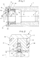
- Fig. 1 is an axial section of a coupling of the present invention,
- Fig. 2 is a section of the part indicated by the arrow II in Fig. 1 on an enlarged scale,
- Fig. 3 is a section similar to Fig. 1 illustrating the coupling coupled to a tube,
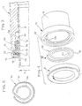
- Fig. 4 is an exploded perspective view of several components of the coupling of the invention,
- Fig. 5 is a plan view of the element indicated by the arrow V in Fig. 4, and
- Fig. 6 and Fig. 7 are axial sections illustrating two variants of the coupling of the invention.
- With reference to the drawings, a metal body indicated 1 is formed with a
cavity 2 intended to receive an end portion of a metal tube 4 (see Fig. 3). Ashoulder 6 is formed in thecavity 2 for abutment by the front end of thetube 4. - To one end of the
body 1 are fixed tworings tube 4. The dimensional tolerances in the outer diameter of thetube 4 and in the inner diameter of therings tube 4 can be inserted without interference with therings cavity 2. - The
ring 10 is forced axially against ashoulder 12 formed in thebody 1 while thering 8 is forced against thering 10 by an inwardly turnededge 14 of thebody 1 which fixes therings body 1. - Between the
rings resilient member 16 constituted by a metal wire shaped into a generally spiral configuration. - As seen in greater detail in Figures 4 and 5, the
member 16 has two concentric, coplanar circular arms indicated 18 and 20. - As seen in particular in Fig. 2, the
rings outer chamber 22 and a radiallyinner chamber 24. Theouter arm 18 of theresilient member 16 is gripped between therings chamber 22 while theinner arm 22 is free to expand radially in thechamber 24 since the axial dimension of the latter is greater than the diameter of the wire constituting themember 16. - With reference to Fig. 2, the
inner arm 20 of theresilient member 16 projects radially into thecavity 2 by distance e which is less than the radius r of the wire constituting themember 16. This ensures that theinner arm 20 deforms radially outwardly during the insertion of the tube without causing the tube to jam against thearm 20 even when the end of thetube 4 has a sharp edge. - The
ring 10 has anaxial seal appendage 26 onto which is fitted anelastomeric sealing member 28. The sealingmember 28 has anannular projection 30 which extends into thecavity 2 and is intended to establish sealing contact with the outer surface of the tube 4 (see Fig. 3). In correspondence with theprojection 30 of thewasher 28, thecavity 2 has apart 2a with a greater diameter than that of thetube 4 so as to allow theprojection 30 to deform axially (see Fig. 3 again). - When the
tube 4 is inserted in thecavity 2 as illustrated in Fig. 3, theinner arm 20 of theelastic member 16 exerts a radially compressive resilient force on the surface of thetube 4 which ensures the electrical connection between themember 16 and thetube 4. - The
member 16 is in turn connected electrically to themetal body 1 by means of therings - At the same time, the
sealing member 28 with itsprojection 30 establishes sealing contact between thetube 4 and thebody 1. - The end of the
body 1 which is not illustrated in the drawings may be made in a similar manner to that described previously or alternatively may be provided with means for fixing thebody 1 to a connector block or the like. - In the variants illustrated in Figures 6 and 7, in which elements corresponding to those described previously are indicated by the same reference numerals, the
rings chambers - In the version of Figure 6, the
sealing member 28 is fitted onto ametal reinforcing member 32 while, in the version of Figure 7, the sealingmember 28 is simply retained between ashoulder 34 of thebody 1 and thesurface 36 of thering 10. - In the variant of Figure 7, the sealing
member 28 has an inner diameter equal to the inner diameter d of therings projection 30 during insertion of the tube.
Claims (6)
- A coupling for metal tubes, in particular for tubes for protecting electrical systems, comprising a metal body (1) having a cavity (2) for receiving the end of a tube (4), and an electrically-conductive resilient member (16) for establishing an electrical contact between the metal body, (1) and the tube (4), characterised in that the resilient member (16) has a substantially spiral form with an outer arm (18) fixed to and in electrical contact with the metal body (1) and an inner arm (20) which can exert a radial compressive force on the surface of the tube (4).
- A coupling according to Claim 1, characterised in that the said part (20) of the resilient member (16) which establishes the electrical contact with the tube (4) has a circular profile with an inner diameter less than the outer diameter of the tube (4) so that, in use, the said part (20) can expand radially as a result of the introduction of the tube (4).
- A coupling according to Claim 1, characterised in that the resilient member (16) is formed from a circular-section wire which, in its undeformed configuration, projects radially into the cavity (2) for receiving the tube (4) by an amount (e) less than the radius (r) of the wire section.
- A coupling according to Claim 1, characterised in that it includes a sealing member (28) of elastomeric material able to establish sealing contact between the tube (4) and the body (1).
- A coupling according to Claim 1, characterised in that the resilient member (16) is housed in a seat defined between two metal rings (8, 10) fixed to the said body (1), the seat having a radially outer chamber (22) in which the outer arm (18) of the resilient member (16) is clamped and a radially inner chamber (24) located in correspondence with the inner arm (20) of the resilient member (16) and whose axial dimension is greater than the thickness of the resilient member (16).
- A coupling according to Claim 5, characterised in that one of the said rings (8, 10) has an axial appendage (6) onto which the sealing member (18) is fitted, the latter having an annular projection (30) projecting radially into the cavity (2) and intended to adhere to the outer surface of the tube (4).
Applications Claiming Priority (2)
| Application Number | Priority Date | Filing Date | Title |
|---|---|---|---|
| ITTO920374A IT1259568B (en) | 1992-04-30 | 1992-04-30 | CONNECTION JOINT FOR METAL TUBES |
| ITTO920374 | 1992-04-30 |
Publications (2)
| Publication Number | Publication Date |
|---|---|
| EP0568032A1 true EP0568032A1 (en) | 1993-11-03 |
| EP0568032B1 EP0568032B1 (en) | 1995-12-06 |
Family
ID=11410432
Family Applications (1)
| Application Number | Title | Priority Date | Filing Date |
|---|---|---|---|
| EP93106879A Expired - Lifetime EP0568032B1 (en) | 1992-04-30 | 1993-04-28 | Coupling for metal tubes |
Country Status (6)
| Country | Link |
|---|---|
| US (1) | US5792990A (en) |
| EP (1) | EP0568032B1 (en) |
| AT (1) | ATE131267T1 (en) |
| DE (1) | DE69300936T2 (en) |
| ES (1) | ES2082545T3 (en) |
| IT (1) | IT1259568B (en) |
Cited By (2)
| Publication number | Priority date | Publication date | Assignee | Title |
|---|---|---|---|---|
| WO2014044275A1 (en) * | 2012-09-19 | 2014-03-27 | Schaeffler Technologies AG & Co. KG | Connecting unit for fastening a hydraulic conduit to a component |
| WO2019025296A3 (en) * | 2017-08-04 | 2019-04-18 | Eaton Intelligent Power Limited | Hydraulic quick connector |
Families Citing this family (13)
| Publication number | Priority date | Publication date | Assignee | Title |
|---|---|---|---|---|
| US3497859A (en) * | 1968-05-28 | 1970-02-24 | Stackpole Carbon Co | Electrical resistors for printed circuits |
| US20060265852A1 (en) * | 2001-01-19 | 2006-11-30 | Victaulic Company | Triple-expanded mechanical pipe coupling derived from a standard fitting |
| US7121593B2 (en) * | 2001-01-19 | 2006-10-17 | Victaulic Company | Triple-expanded mechanical pipe coupling derived from a standard fitting |
| US20040239115A1 (en) * | 2001-01-19 | 2004-12-02 | Victaulic Company Of America | Mechanical pipe coupling derived from a standard fitting |
| US20050146133A1 (en) * | 2001-01-19 | 2005-07-07 | Victaulic Company Of America | Mechanical pipe coupling derived from a standard fitting |
| US7500699B2 (en) * | 2001-01-19 | 2009-03-10 | Victaulic Company | Clamping mechanical pipe coupling derived from a standard fitting |
| US6913292B2 (en) * | 2001-01-19 | 2005-07-05 | Victaulic Company Of America | Mechanical pipe coupling derived from a standard fitting |
| US20020135184A1 (en) * | 2001-01-19 | 2002-09-26 | Snyder Ronald R. | Mechanical pipe coupling derived from a standard fitting |
| US6805383B2 (en) * | 2001-11-12 | 2004-10-19 | Itt Manufacturing Enterprises, Inc. | Fluid quick connector with secure electrical contact |
| GB0411099D0 (en) * | 2004-05-19 | 2004-06-23 | Oystertec Plc | Pipe fitting |
| US7866711B2 (en) * | 2006-08-22 | 2011-01-11 | Ti Group Automotive Systems, Llc | Quick connector with conductive path |
| WO2008092682A1 (en) * | 2007-02-01 | 2008-08-07 | Ibp Conex Limited | Insertion and release tool for pipe fitting arrangement and method using such tool |
| GB0815203D0 (en) * | 2008-08-20 | 2008-09-24 | Airbus Uk Ltd | A connector for a pipe and bonding means for use therein |
Citations (6)
| Publication number | Priority date | Publication date | Assignee | Title |
|---|---|---|---|---|
| BE468162A (en) * | ||||
| US2058062A (en) * | 1936-05-09 | 1936-10-20 | Cowles Irving | Swivel joint |
| US2966539A (en) * | 1957-10-07 | 1960-12-27 | American Cast Iron Pipe Co | Electrically conductive pipe joint and gasket |
| US3093703A (en) * | 1960-11-07 | 1963-06-11 | Killark Electric Mfg Company | Expansion fitting for electrical conduits |
| US3783178A (en) * | 1972-08-03 | 1974-01-01 | Gen Signal Corp | Expansion joint for connecting rigid conduit with grounding continuity |
| US4082326A (en) * | 1976-08-30 | 1978-04-04 | Canadian Brass Limited | Compressible member for use in compression joint pipe connector |
Family Cites Families (16)
| Publication number | Priority date | Publication date | Assignee | Title |
|---|---|---|---|---|
| US1800254A (en) * | 1926-12-18 | 1931-04-14 | Frank J Holmes | Handle and the like |
| US2425500A (en) * | 1943-07-07 | 1947-08-12 | Wiggins Irene Lane | Valved coupling |
| US2506447A (en) * | 1947-04-04 | 1950-05-02 | Garlock Packing Co | Sealing device |
| US2900436A (en) * | 1958-03-06 | 1959-08-18 | Arthur I Appleton | Electrical conduit union and expansion coupling |
| US3166345A (en) * | 1960-06-10 | 1965-01-19 | Rector Well Equipment Company | Metallic seal assembly |
| US3186736A (en) * | 1962-10-02 | 1965-06-01 | Warshawsky Jerome | Limited universal swivel joint fittings for electric conduits |
| US3296361A (en) * | 1964-05-05 | 1967-01-03 | Samuel M Markland | Universally self-adjusting fitting |
| US3884508A (en) * | 1973-12-10 | 1975-05-20 | Eugene G Jones | Pipe couplings |
| US3907334A (en) * | 1974-11-04 | 1975-09-23 | Jr Enos L Schera | Linear adjustable telescopic nipple |
| US4072328A (en) * | 1976-05-25 | 1978-02-07 | Hepworth Plastics Limited | Pipe couplings |
| US4434541A (en) * | 1980-12-22 | 1984-03-06 | Chomerics, Inc. | Electromagnetic shielding |
| CH665700A5 (en) * | 1984-07-10 | 1988-05-31 | Cejn Ag | DETACHABLE SLEEVE PIPE CONNECTION. |
| US5248850A (en) * | 1992-06-29 | 1993-09-28 | Laney Robbye J | Electrical box connector conduit |
| US5307037A (en) * | 1992-10-28 | 1994-04-26 | General Electric Company | Shim lead assembly with flexible castellated connector for superconducting magnet |
| DE4240279C2 (en) * | 1992-12-01 | 2003-04-17 | Voss Armaturen | Connection device for hose and / or pipes |
| US5355909A (en) * | 1994-02-07 | 1994-10-18 | National Coupling Company, Inc. | Undersea hydraulic coupling with metal seals |
-
1992
- 1992-04-30 IT ITTO920374A patent/IT1259568B/en active IP Right Grant
-
1993
- 1993-04-28 AT AT93106879T patent/ATE131267T1/en not_active IP Right Cessation
- 1993-04-28 EP EP93106879A patent/EP0568032B1/en not_active Expired - Lifetime
- 1993-04-28 DE DE69300936T patent/DE69300936T2/en not_active Expired - Fee Related
- 1993-04-28 ES ES93106879T patent/ES2082545T3/en not_active Expired - Lifetime
- 1993-04-29 US US08/054,907 patent/US5792990A/en not_active Expired - Fee Related
Patent Citations (6)
| Publication number | Priority date | Publication date | Assignee | Title |
|---|---|---|---|---|
| BE468162A (en) * | ||||
| US2058062A (en) * | 1936-05-09 | 1936-10-20 | Cowles Irving | Swivel joint |
| US2966539A (en) * | 1957-10-07 | 1960-12-27 | American Cast Iron Pipe Co | Electrically conductive pipe joint and gasket |
| US3093703A (en) * | 1960-11-07 | 1963-06-11 | Killark Electric Mfg Company | Expansion fitting for electrical conduits |
| US3783178A (en) * | 1972-08-03 | 1974-01-01 | Gen Signal Corp | Expansion joint for connecting rigid conduit with grounding continuity |
| US4082326A (en) * | 1976-08-30 | 1978-04-04 | Canadian Brass Limited | Compressible member for use in compression joint pipe connector |
Cited By (2)
| Publication number | Priority date | Publication date | Assignee | Title |
|---|---|---|---|---|
| WO2014044275A1 (en) * | 2012-09-19 | 2014-03-27 | Schaeffler Technologies AG & Co. KG | Connecting unit for fastening a hydraulic conduit to a component |
| WO2019025296A3 (en) * | 2017-08-04 | 2019-04-18 | Eaton Intelligent Power Limited | Hydraulic quick connector |
Also Published As
| Publication number | Publication date |
|---|---|
| ITTO920374A0 (en) | 1992-04-30 |
| US5792990A (en) | 1998-08-11 |
| DE69300936D1 (en) | 1996-01-18 |
| ATE131267T1 (en) | 1995-12-15 |
| ES2082545T3 (en) | 1996-03-16 |
| DE69300936T2 (en) | 1996-05-15 |
| ITTO920374A1 (en) | 1993-10-30 |
| IT1259568B (en) | 1996-03-20 |
| EP0568032B1 (en) | 1995-12-06 |
Similar Documents
| Publication | Publication Date | Title |
|---|---|---|
| EP0568032B1 (en) | Coupling for metal tubes | |
| AU674245B2 (en) | Connector for coaxial cable having corrugated outer conductor and method of attachment | |
| US6042422A (en) | Coaxial cable end connector crimped by axial compression | |
| US5172940A (en) | Connector device for connecting small diameter pipe | |
| US4885429A (en) | Metal clad cable connector | |
| US5342096A (en) | Connector with captive sealing ring | |
| US5498043A (en) | Hose fitting having ferrule anti-rotation ratchet teeth | |
| US7288002B2 (en) | Coaxial cable connector with self-gripping and self-sealing features | |
| US4063760A (en) | Quick connect coupling | |
| CN100456570C (en) | Push-on connector interface | |
| RU2305886C2 (en) | Tight coaxial cable connector and associated method | |
| US5992898A (en) | Quick-connect assembly and method of manufacture | |
| US4022966A (en) | Ground connector | |
| US4400022A (en) | Tube connector | |
| US7002077B2 (en) | Threadless conduit fitting including continuous compression ring | |
| US4983784A (en) | Cable termination apparatus and method | |
| EP0447144A1 (en) | Plug and socket electrical connection assembly | |
| EP0495467A2 (en) | Self-flaring connector for coaxial cable having a helically corrugated outer conductor | |
| IE44172B1 (en) | Submersible pipe electrical cable assembly | |
| US4702543A (en) | Environmental seal and alignment means for an electromagnetically formed backshell | |
| EP0798815A3 (en) | Connector assembly for a coaxial cable having a corrugated outer conductor | |
| US4316053A (en) | Pipe couplings and coupling gaskets | |
| US20030080564A1 (en) | Pipe joint assembly and method for assembling the same | |
| GB2284510A (en) | Electrical connector | |
| EP0114455A1 (en) | A coupling for a conduit |
Legal Events
| Date | Code | Title | Description |
|---|---|---|---|
| PUAI | Public reference made under article 153(3) epc to a published international application that has entered the european phase |
Free format text: ORIGINAL CODE: 0009012 |
|
| AK | Designated contracting states |
Kind code of ref document: A1 Designated state(s): AT BE CH DE DK ES FR GB GR IE IT LI LU MC NL PT SE |
|
| 17P | Request for examination filed |
Effective date: 19940219 |
|
| 17Q | First examination report despatched |
Effective date: 19950314 |
|
| GRAA | (expected) grant |
Free format text: ORIGINAL CODE: 0009210 |
|
| AK | Designated contracting states |
Kind code of ref document: B1 Designated state(s): AT BE CH DE DK ES FR GB GR IE IT LI LU MC NL PT SE |
|
| PG25 | Lapsed in a contracting state [announced via postgrant information from national office to epo] |
Ref country code: NL Free format text: LAPSE BECAUSE OF FAILURE TO SUBMIT A TRANSLATION OF THE DESCRIPTION OR TO PAY THE FEE WITHIN THE PRESCRIBED TIME-LIMIT Effective date: 19951206 Ref country code: MC Free format text: LAPSE BECAUSE OF NON-PAYMENT OF DUE FEES Effective date: 19951206 Ref country code: LI Effective date: 19951206 Ref country code: GR Free format text: LAPSE BECAUSE OF FAILURE TO SUBMIT A TRANSLATION OF THE DESCRIPTION OR TO PAY THE FEE WITHIN THE PRESCRIBED TIME-LIMIT Effective date: 19951206 Ref country code: DK Effective date: 19951206 Ref country code: CH Effective date: 19951206 Ref country code: BE Effective date: 19951206 Ref country code: AT Effective date: 19951206 |
|
| REF | Corresponds to: |
Ref document number: 131267 Country of ref document: AT Date of ref document: 19951215 Kind code of ref document: T |
|
| REG | Reference to a national code |
Ref country code: IE Ref legal event code: FG4D Free format text: 66433 |
|
| ITF | It: translation for a ep patent filed |
Owner name: JACOBACCI & PERANI S.P.A. |
|
| REF | Corresponds to: |
Ref document number: 69300936 Country of ref document: DE Date of ref document: 19960118 |
|
| PG25 | Lapsed in a contracting state [announced via postgrant information from national office to epo] |
Ref country code: SE Effective date: 19960306 Ref country code: PT Effective date: 19960306 |
|
| REG | Reference to a national code |
Ref country code: ES Ref legal event code: FG2A Ref document number: 2082545 Country of ref document: ES Kind code of ref document: T3 |
|
| ET | Fr: translation filed | ||
| PG25 | Lapsed in a contracting state [announced via postgrant information from national office to epo] |
Ref country code: IE Free format text: LAPSE BECAUSE OF NON-PAYMENT OF DUE FEES Effective date: 19960428 |
|
| PG25 | Lapsed in a contracting state [announced via postgrant information from national office to epo] |
Ref country code: LU Free format text: LAPSE BECAUSE OF NON-PAYMENT OF DUE FEES Effective date: 19960430 |
|
| NLV1 | Nl: lapsed or annulled due to failure to fulfill the requirements of art. 29p and 29m of the patents act | ||
| REG | Reference to a national code |
Ref country code: CH Ref legal event code: PL |
|
| PLBE | No opposition filed within time limit |
Free format text: ORIGINAL CODE: 0009261 |
|
| STAA | Information on the status of an ep patent application or granted ep patent |
Free format text: STATUS: NO OPPOSITION FILED WITHIN TIME LIMIT |
|
| 26N | No opposition filed | ||
| REG | Reference to a national code |
Ref country code: GB Ref legal event code: IF02 |
|
| PGFP | Annual fee paid to national office [announced via postgrant information from national office to epo] |
Ref country code: ES Payment date: 20070306 Year of fee payment: 15 |
|
| PGFP | Annual fee paid to national office [announced via postgrant information from national office to epo] |
Ref country code: GB Payment date: 20070315 Year of fee payment: 15 |
|
| PGFP | Annual fee paid to national office [announced via postgrant information from national office to epo] |
Ref country code: DE Payment date: 20070326 Year of fee payment: 15 |
|
| PGFP | Annual fee paid to national office [announced via postgrant information from national office to epo] |
Ref country code: FR Payment date: 20070430 Year of fee payment: 15 |
|
| PGFP | Annual fee paid to national office [announced via postgrant information from national office to epo] |
Ref country code: IT Payment date: 20080313 Year of fee payment: 16 |
|
| GBPC | Gb: european patent ceased through non-payment of renewal fee |
Effective date: 20080428 |
|
| PG25 | Lapsed in a contracting state [announced via postgrant information from national office to epo] |
Ref country code: DE Free format text: LAPSE BECAUSE OF NON-PAYMENT OF DUE FEES Effective date: 20081101 |
|
| REG | Reference to a national code |
Ref country code: FR Ref legal event code: ST Effective date: 20081231 |
|
| PG25 | Lapsed in a contracting state [announced via postgrant information from national office to epo] |
Ref country code: FR Free format text: LAPSE BECAUSE OF NON-PAYMENT OF DUE FEES Effective date: 20080430 |
|
| REG | Reference to a national code |
Ref country code: ES Ref legal event code: FD2A Effective date: 20080429 |
|
| PG25 | Lapsed in a contracting state [announced via postgrant information from national office to epo] |
Ref country code: GB Free format text: LAPSE BECAUSE OF NON-PAYMENT OF DUE FEES Effective date: 20080428 |
|
| PG25 | Lapsed in a contracting state [announced via postgrant information from national office to epo] |
Ref country code: ES Free format text: LAPSE BECAUSE OF NON-PAYMENT OF DUE FEES Effective date: 20080429 |
|
| PG25 | Lapsed in a contracting state [announced via postgrant information from national office to epo] |
Ref country code: IT Free format text: LAPSE BECAUSE OF NON-PAYMENT OF DUE FEES Effective date: 20090428 |