EP0567817B1 - Trial frames - Google Patents
Trial frames Download PDFInfo
- Publication number
- EP0567817B1 EP0567817B1 EP93105809A EP93105809A EP0567817B1 EP 0567817 B1 EP0567817 B1 EP 0567817B1 EP 93105809 A EP93105809 A EP 93105809A EP 93105809 A EP93105809 A EP 93105809A EP 0567817 B1 EP0567817 B1 EP 0567817B1
- Authority
- EP
- European Patent Office
- Prior art keywords
- test
- temple
- glasses
- accordance
- bridge
- Prior art date
- Legal status (The legal status is an assumption and is not a legal conclusion. Google has not performed a legal analysis and makes no representation as to the accuracy of the status listed.)
- Expired - Lifetime
Links
Images


Classifications
-
- A—HUMAN NECESSITIES
- A61—MEDICAL OR VETERINARY SCIENCE; HYGIENE
- A61B—DIAGNOSIS; SURGERY; IDENTIFICATION
- A61B3/00—Apparatus for testing the eyes; Instruments for examining the eyes
- A61B3/10—Objective types, i.e. instruments for examining the eyes independent of the patients' perceptions or reactions
- A61B3/11—Objective types, i.e. instruments for examining the eyes independent of the patients' perceptions or reactions for measuring interpupillary distance or diameter of pupils
- A61B3/111—Objective types, i.e. instruments for examining the eyes independent of the patients' perceptions or reactions for measuring interpupillary distance or diameter of pupils for measuring interpupillary distance
-
- A—HUMAN NECESSITIES
- A61—MEDICAL OR VETERINARY SCIENCE; HYGIENE
- A61B—DIAGNOSIS; SURGERY; IDENTIFICATION
- A61B3/00—Apparatus for testing the eyes; Instruments for examining the eyes
- A61B3/02—Subjective types, i.e. testing apparatus requiring the active assistance of the patient
- A61B3/028—Subjective types, i.e. testing apparatus requiring the active assistance of the patient for testing visual acuity; for determination of refraction, e.g. phoropters
- A61B3/04—Trial frames; Sets of lenses for use therewith
-
- G—PHYSICS
- G02—OPTICS
- G02C—SPECTACLES; SUNGLASSES OR GOGGLES INSOFAR AS THEY HAVE THE SAME FEATURES AS SPECTACLES; CONTACT LENSES
- G02C13/00—Assembling; Repairing; Cleaning
- G02C13/003—Measuring during assembly or fitting of spectacles
Definitions
- the invention relates to measuring glasses for receiving spherical, prismatic and cylindrical measuring glasses with a bridge with two attached and axially displaceable main bodies for fastening the glasses holder and a nose height adjustment and with length and height adjustable brackets.
- test glasses of the type mentioned above special test glasses are used for the determination of glasses, which must be easy to replace.
- the trial glasses must also be rotatable in order to be able to correct astigmatic errors precisely in their axial position.
- side and height errors which are corrected via prisms, must also be adjustable exactly to the base position. This presupposes that the measuring glasses must be able to be adjusted precisely to the patient.
- the so-called pupil distance must be set exactly, in such a way that the pupil center of each eye can be set separately.
- an adjustable nose pad is attached to the middle of the bridge of the measuring glasses, which must be pivotable as well as adjustable in height.
- the glasses wings must be adjustable in length and in the Height adjustable to be able to be adapted exactly to the different ear shapes.
- the bracket is also formed with a sliding mechanism which is open on the outside, so that the patient's hair can become jammed here.
- Another weak point of the known glasses is that the holder for holding the glasses consisted of a triple spring, which slowed down relatively early with frequent use and could also break off in the long run.
- the invention has for its object to propose a pair of measuring glasses of the type mentioned, which allows significantly improved handling, at least with the same weight, in which the measuring glasses are easier to change and replace and are also easier to turn, in addition to which the adjustability of the nose height adjustment and the bracket is simplified and no more hair can get stuck in the adjustment.
- a self-locking drive is proposed for the nose height adjustment, so that both the pivoting and the height adjustment is possible with a single control button and there is no annoying tightening of the lock nut.
- the temples of the measuring glasses these are adjustable in height and can be pivoted about a joint that runs perpendicular to the longitudinal axis of the temple. This joint is attached to a telescopic part, the part adjoining the joint engaging over the inner telescopic part on all sides. This ensures that there are no variable gaps in the area of the hair into which hair can be pinched.
- the distance between the bridge and the receptacles for the measuring glasses was deliberately chosen to be larger than with conventional glasses, so that the glasses can be removed more easily from their holders. Furthermore, the controls have been moved a little further out so that the refractionist is in no way annoying to the patient when the measuring glasses are adjusted. Furthermore, the controls for tactile perception have been significantly improved.
- the cylinder elements and also the elements for nose height adjustment were made spherical.
- the elements for the bridge adjustment for exact PD adjustment were cylindrical.
- the visor rod for the corneal crest dimension was inserted directly on the main body on a guide provided.
- the nose height adjustment is provided with a self-locking drive, so that the nose pad can be conveniently and individually adjusted using a rotary knob.
- a spherical control element is used for this. If you let go of this spherical control element, the nose pad is locked in place at the set point. Additional countering, as in the prior art, is not required.
- the nose height adjustment can be pivoted, whereby this pivoting is locked even when the same button is released.
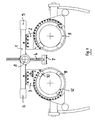
- Fig. 1 denotes the bridge on which the two main bodies 2, 3 and the nose height adjustment 4 are attached.
- Two adjustment elements 5, 6 are used for the lateral adjustment of the main body 2, 3 relative to the nose height adjustment.
- the pupil distance can be read on a measuring scale which is arranged on the main body and is pivoted with it relative to the bridge 1.
- the nose height adjustment 4 is on the one hand pivotally attached to the measuring bridge 1 in order to adjust the nose support 7 in such a way that the glasses can be precisely aligned with the eye. Furthermore, the nose height adjustment 4 is adjustable in height to the bridge 1, for which purpose an adjusting button 8 is used which actuates a self-locking gear. After adjusting and releasing the button 8, the nose height adjustment 4 is fixed in its position relative to the bridge 1.
- Each main body 2, 3 receives a rotatable ring 9, on which three webs, 10, 11 and 12 are fastened, which are at a distance of slightly more than 90 ° from one another, so that the measuring glass 13 shown in FIG. 3 is slightly more is included as 180 °. Furthermore, the web 12 is resilient, so that the measuring glasses 13 are easy to use and are held securely.
- Rotary drives which can be actuated via spherical operating elements 14, serve to adjust the ring 9.
- Up to three measuring glasses can be used on the front of the glasses, while two measuring glasses can be used on the back of the glasses.
- two webs 15, 16 serve to hold the measuring glasses, these being non-resilient, but having a larger circumference.
- the bridge 1 was raised relative to the measuring glasses 13, on the one hand to facilitate the insertion of the measuring glasses 13 and to be able to carry out the settings with a relatively large distance from the patient's head.
Landscapes
- Health & Medical Sciences (AREA)
- Life Sciences & Earth Sciences (AREA)
- Physics & Mathematics (AREA)
- Ophthalmology & Optometry (AREA)
- Surgery (AREA)
- Molecular Biology (AREA)
- Biophysics (AREA)
- Engineering & Computer Science (AREA)
- Biomedical Technology (AREA)
- Heart & Thoracic Surgery (AREA)
- Medical Informatics (AREA)
- Veterinary Medicine (AREA)
- Public Health (AREA)
- Animal Behavior & Ethology (AREA)
- General Health & Medical Sciences (AREA)
- General Physics & Mathematics (AREA)
- Optics & Photonics (AREA)
- Eyeglasses (AREA)
- Eye Examination Apparatus (AREA)
Description
Die Erfindung betrifft eine Meßbrille zur Aufnahme von sphärischen, prismatischen und zylindrischen Meßgläsern mit einer Brücke mit zwei hieran befestigten und axial verschiebbaren Hauptkörpern für die Befestigung der Brillenglashalter und einer Nasenhöhenverstellung und mit längen- und höhenverstellbaren Bügeln.The invention relates to measuring glasses for receiving spherical, prismatic and cylindrical measuring glasses with a bridge with two attached and axially displaceable main bodies for fastening the glasses holder and a nose height adjustment and with length and height adjustable brackets.
In Meßbrillen der vorstehend genannten Art werden zur Brillenglasbestimmung spezielle Probiergläser eingesetzt, die leicht austauschbar sein müssen. Die Probiergläser müssen darüberhinaus auch drehbar angeordnet sein, um astigmatische Fehler genau in ihrer Achslage auskorrigieren zu können. Des weiteren müssen auch Seiten- und Höhenfehler, die über Prismen korrigiert werden, genau zur Basislage einstellbar sein. Dies setzt voraus, daß die Meßbrillen genau auf den Patienten eingestellt werden können müssen. Das heißt, es muß zum einen der sogenannte Pupillenabstand exakt eingestellt werden, und zwar so, daß die Pupillenmitte eines jeden Auges separat einstellbar ist. Bei den bekannten Meßbrillen ist des weiteren an der Brückenmitte der Meßbrille eine verstellbare Nasenauflage befestigt, die sowohl schwenkbar wie auch in der Höhe einstellbar sein muß. Die Brillenflügel müssen längenveränderbar und in der Höhe verstellbar ausgebildet sein, um exakt den unterschiedlichen Ohrformen angepaßt werden zu können. Diese Meßbrillen müssen des weiteren dafür geeignet sein, bis zu fünf Gläser pro Auge aufnehmen zu können, wobei das Austauschen der Gläser schnell und einfach vonstatten gehen muß.In test glasses of the type mentioned above, special test glasses are used for the determination of glasses, which must be easy to replace. In addition, the trial glasses must also be rotatable in order to be able to correct astigmatic errors precisely in their axial position. Furthermore, side and height errors, which are corrected via prisms, must also be adjustable exactly to the base position. This presupposes that the measuring glasses must be able to be adjusted precisely to the patient. This means that, on the one hand, the so-called pupil distance must be set exactly, in such a way that the pupil center of each eye can be set separately. In the known measuring glasses, an adjustable nose pad is attached to the middle of the bridge of the measuring glasses, which must be pivotable as well as adjustable in height. The glasses wings must be adjustable in length and in the Height adjustable to be able to be adapted exactly to the different ear shapes. These measuring glasses must also be suitable for being able to hold up to five glasses per eye, the glasses having to be exchanged quickly and easily.
Bei den bekannten Meßbrillen ist es relativ schwierig und umständlich, die Meßgläser auszutauschen. Des weiteren ist es umständlich, die Nasenhöhenverstellung und den Schwenkmechanismus einzustellen, da hier nicht nur eine Verschiebung, sondern darüberhinaus mit einer Kontermutter eine Arretierung der Nasenhöhenverstellung an der Brücke vorgenommen werden muß. Bei den bekannten Meßbrillen ist darüberhinaus der Bügel mit einem Verschiebemechanismus ausgebildet, der außenliegend offen ist, so daß sich Haare des Patienten hier verklemmen können. Ein weiterer Schwachpunkt der bekannten Brillen besteht darin, daß die Halterung für die Aufnahme der Brillengläser aus einer Dreifachfeder bestand, die bei häufigem Gebrauch relativ früh erlahmt und auf Dauer auch abbrechen konnte.In the known measuring glasses, it is relatively difficult and cumbersome to replace the measuring glasses. Furthermore, it is cumbersome to adjust the nose height adjustment and the swivel mechanism, since not only a shift, but also a lock nut must be used to lock the nose height adjustment on the bridge. In the known measuring glasses, the bracket is also formed with a sliding mechanism which is open on the outside, so that the patient's hair can become jammed here. Another weak point of the known glasses is that the holder for holding the glasses consisted of a triple spring, which slowed down relatively early with frequent use and could also break off in the long run.
Der Erfindung liegt die Aufgabe zugrunde, eine Meßbrille der eingangs genannten Art vorzuschlagen, die zumindest bei gleichem Gewicht eine deutlich verbesserte Handhabung gestattet, bei der die Meßgläser leichter ein- und auszuwechseln sind und auch leichter verdrehbar sind, bei der darüberhinaus die Einstellbarkeit der Nasenhöhenverstellung und des Bügels vereinfacht ist und sich keine Haare mehr bei der Verstellung in diesen verklemmen können.The invention has for its object to propose a pair of measuring glasses of the type mentioned, which allows significantly improved handling, at least with the same weight, in which the measuring glasses are easier to change and replace and are also easier to turn, in addition to which the adjustability of the nose height adjustment and the bracket is simplified and no more hair can get stuck in the adjustment.
Diese Aufgabe wird mit den Merkmalen des Anspruches 1 gelöst.This object is achieved with the features of claim 1.
Für die Nasenhöhenverstellung wird ein selbsthemmender Antrieb vorgeschlagen, so daß sowohl die Verschwenkung wie auch die Höhenverstellung mit einem einzigen Bedienknopf möglich ist und ein lästiges Anziehen der Kontermutter entfällt. Für die Aufnahme der Meßgläser dienen drei Stege, die entsprechende Aufnahmenuten für die einzelnen Meßgläser aufweisen, wobei einer dieser Stege vorteilhaft federnd ausgebildet ist. Diese Stege sind jeweils in einem Abstand von etwas mehr als 90° auf einem Kreisumfang angeordnet, so daß sichergestellt ist, daß die in etwa fast bis 360° drehbaren Brillengläser nicht aus den Halterungen herausfallen können. Was die Bügel der Meßbrille betrifft, so sind diese in der Höhe verstellbar um ein Gelenk schwenkbar, das senkrecht zur Bügellängsachse verläuft. Dieses Gelenk ist an einem Teleskopteil befestigt, wobei das sich an das Gelenk anschließende Teil das innenliegende Teleskopteil allseitig übergreift. Hierdurch ist sichergestellt, daß im Bereich der Haare keine veränderlichen Spalten entstehen, in die Haare eingeklemmt werden können.A self-locking drive is proposed for the nose height adjustment, so that both the pivoting and the height adjustment is possible with a single control button and there is no annoying tightening of the lock nut. There are three webs for receiving the measuring glasses, which have corresponding receiving grooves for the individual measuring glasses, one of these webs advantageously being of resilient design. These webs are each arranged at a distance of a little more than 90 ° on a circumference, so that it is ensured that the eyeglass lenses, which can be rotated almost up to 360 °, cannot fall out of the holders. As for the temples of the measuring glasses, these are adjustable in height and can be pivoted about a joint that runs perpendicular to the longitudinal axis of the temple. This joint is attached to a telescopic part, the part adjoining the joint engaging over the inner telescopic part on all sides. This ensures that there are no variable gaps in the area of the hair into which hair can be pinched.
Der Abstand der Brücke zu den Aufnahmen für die Meßgläser wurde bewußt größer als bei den herkömmlichen Brillen gewählt, damit die Gläser einfacher aus ihren Halterungen herausnehmbar sind. Des weiteren wurden auch die Bedienelemente etwas weiter nach außen gelegt, so daß beim Verstellen der Meßbrille der Refraktionist den Patienten in keiner Weise belästigt. Des weiteren wurden die Bedienelemente für die Tastwahrnehmung deutlich verbessert. Die Zylinderelemente und auch die Elemente zur Nasenhöhenverstellung wurden kugelartig ausgeführt. Die Elemente für die Brückenverstellung zur exakten PD-Anpassung wurden zylindrisch ausgebildet.The distance between the bridge and the receptacles for the measuring glasses was deliberately chosen to be larger than with conventional glasses, so that the glasses can be removed more easily from their holders. Furthermore, the controls have been moved a little further out so that the refractionist is in no way annoying to the patient when the measuring glasses are adjusted. Furthermore, the controls for tactile perception have been significantly improved. The cylinder elements and also the elements for nose height adjustment were made spherical. The elements for the bridge adjustment for exact PD adjustment were cylindrical.
Die Höhenverstellung der Bügel wurde durch einen komplett neuen Mechanismus ersetzt. Dabei wird ein Bedienrad, auf dessen Innenseite eine Kurvenführung eingespritzt ist, nach rechts bzw. links bewegt, wodurch die Aufwärts- und Abwärtsbewegungen synchron erfolgen.The height adjustment of the bracket has been replaced by a completely new mechanism. An operating wheel, on the inside of which a curve guide is injected, is moved to the right or left, as a result of which the upward and downward movements take place synchronously.
Die Hauptkörper der Meßbrille können in Kunststoff ausgeführt werden, wobei die Brillenglashalter mit ihren drei Stegen aus einem Aluminium-Druckguß hergestellt werden. Auf diese Stege werden dann Kunststofformteile aufgesteckt, die zur Aufnahme der Meßgläser dienen.The main body of the measuring glasses can be made of plastic, the glasses holder with their three webs being made of die-cast aluminum. Plastic moldings are then plugged onto these webs, which are used to hold the measuring glasses.
Der Visierstab zur Hornhautscheitelabmessung wurde direkt an dem Hauptkörper an einer vorgesehenen Führung eingeschoben. Die Nasenhöhenverstellung ist mit einem selbsthemmenden Antrieb versehen, so daß über einen Drehknopf die Nasenauflage bequem und individuell angepaßt werden kann. Hierfür dient ein kugeliges Bedienungselement. Läßt man dieses kugelige Bedienungselement los, so ist die Nasenauflage an der eingestellten Stelle direkt arretiert. Ein ergänzendes Kontern, wie beim Stand der Technik, entfällt. Um die Brille parallel vor die Patientenaugen setzen zu können, ist die Nasenhöhenverstellung verschwenkbar, wobei diese Verschwenkung auch bei Loslassen des gleichen Knopfes arretiert wird.The visor rod for the corneal crest dimension was inserted directly on the main body on a guide provided. The nose height adjustment is provided with a self-locking drive, so that the nose pad can be conveniently and individually adjusted using a rotary knob. A spherical control element is used for this. If you let go of this spherical control element, the nose pad is locked in place at the set point. Additional countering, as in the prior art, is not required. In order to be able to place the glasses in front of the patient's eyes in parallel, the nose height adjustment can be pivoted, whereby this pivoting is locked even when the same button is released.
Ein Ausführungsbeispiel der Erfindung ist im folgenden anhand der Zeichnung näher beschrieben. In dieser zeigen
- Fig. 1
- eine Vorderansicht einer erfindungsgemäß ausgebildeten Meßbrille,
- Fig. 2
- eine Rückansicht der Meßbrille und
- Fig. 3
- die in Fig. 1 gezeigte Meßbrille mit eingesetzten Meßgläsern.
- Fig. 1
- 2 shows a front view of measuring glasses designed according to the invention,
- Fig. 2
- a rear view of the measuring glasses and
- Fig. 3
- the measuring glasses shown in Fig. 1 with inserted measuring glasses.
In Fig. 1 bezeichnet 1 die Brücke, an der die beiden Hauptkörper 2, 3 sowie die Nasenhöhenverstellung 4 befestigt sind. Zwei Verstellelemente 5, 6 dienen zur seitlichen Verstellung der Hauptkörper 2, 3 relativ zur Nasenhöhenverstellung. Der Pupillenabstand kann an einer Meßskala abgelesen werden, die am Hauptkörper angeordnet ist und mit diesem relativ zur Brücke 1 verschwenkt wird.In Fig. 1, 1 denotes the bridge on which the two
Die Nasenhöhenverstellung 4 ist zum einen schwenkbar an der Meßbrücke 1 befestigt, um die Nasenstütze 7 derart einzustellen, daß die Brille exakt zum Auge ausrichtbar ist. Des weiteren ist die Nasenhöhenverstellung 4 in der Höhe zur Brücke 1 verstellbar, wozu ein Stellknopf 8 dient, der ein selbsthemmendes Getriebe betätigt. Nach Einstellung und Loslassen des Knopfes 8 ist die Nasenhöhenverstellung 4 in ihrer relativen Lage zur Brücke 1 fixiert.The
Jeder Hauptkörper 2, 3 nimmt einen drehbaren Ring 9 auf, auf dem drei Stege, 10, 11 und 12 befestigt sind, die zueinander einen Abstand von etwas mehr als 90° aufweisen, so daß das in Fig. 3 gezeigte Meßglas 13 auf etwas mehr als 180° umfaßt wird. Des weiteren ist der Steg 12 federnd ausgebildet, so daß die Meßgläser 13 einfach einsetzbar und sicher gehalten sind.Each
Zur Verstellung des Ringes 9 dienen Drehantriebe, die über kugelförmige Bedienungselemente 14 betätigbar sind. Auf der Vorderseite der Brille können bis zu drei Meßgläser eingesetzt werden, während auf der Rückseite der Brille zwei Meßgläser einsetzbar sind. Auf der Rückseite der Brille dienen zwei Stege 15, 16 zur Aufnahme der Meßgläser, wobei diese nicht federnd, jedoch mit einem größeren Umfang ausgebildet sind.Rotary drives, which can be actuated via
An jedem Hauptträger 2, 3 ist ein Stift an dessen Rückseite befestigt, auf dem ein Teil 17 des Bügels 18 aufgeschoben ist. Der Stift greift in einen Bogen des Teiles 17 ein, wobei die Arretierung durch Selbsthemmung erfolgt. Am Ende des Teiles 17 ist ein senkrecht zum Bügel 18 verlaufendes Gelenk 19 angebracht, um das das Bügelende 20 schwenkbar ist.A pin is attached to the rear of each
Die Brücke 1 wurde relativ zu den Meßgläsern 13 hochgesetzt, um zum einen das Einsetzen der Meßgläser 13 zu erleichtern und um die Einstellungen mit einem relativ großen Abstand zum Kopf des Patienten durchführen zu können.The bridge 1 was raised relative to the
Claims (6)
- Test spectacles for receiving spherical, prismatic and cylindrical test lenses (13), having a bridge (1) with two main bodies (2, 3) which are secured thereto, are axially displaceable and are for securing the spectacle lens holders and a nose vertical adjustment device (4), and having longitudinally and vertically adjustable temples (18), each temple being composed of a front part (17) and a rear longitudinally-adjustable part which are pivotably connected to one another via a joint (19) with a horizontal axis, characterised in that the spectacle lens holding device is composed of three flanges (10, 11, 12) secured on an adjustable ring (9), at least one flange (12) being resilient, in that the nose vertical adjustment device (4) pivotably secured to the bridge (1) is provided with a self-locking drive, and in that the rear part of the temple is composed of parts which can be slid into one another in a telescopic manner.
- Test spectacles in accordance with Claim 1, characterised in that on the flanges there are placed flexible plastics parts having receivers for the test lenses (13).
- Test spectacles in accordance with Claim 1 or 2, characterised in that adjustment of the temple inclination takes place via an operating element having a cam which moves the temple downwards upon rotation to the right and moves the temple upwards upon rotation to the left.
- Test spectacles in accordance with any one of Claims 1 to 3, characterised in that the operating elements for adjustment of cylinder axis or prism base position and for the nose vertical adjustment device are spherical.
- Test spectacles in accordance with any one of Claims 1 to 4, characterised in that the operating elements at the bridge for adjustment of the pupil spacing are cylindrical.
- Test spectacles in accordance with any one of Claims 1 to 5, characterised in that the rotatable ring (9) is of metal and is secured in a plastics guiding device.
Applications Claiming Priority (2)
| Application Number | Priority Date | Filing Date | Title |
|---|---|---|---|
| DE9205768U DE9205768U1 (en) | 1992-04-29 | 1992-04-29 | Measuring glasses |
| DE9205768U | 1992-04-29 |
Publications (2)
| Publication Number | Publication Date |
|---|---|
| EP0567817A1 EP0567817A1 (en) | 1993-11-03 |
| EP0567817B1 true EP0567817B1 (en) | 1996-01-10 |
Family
ID=6878949
Family Applications (1)
| Application Number | Title | Priority Date | Filing Date |
|---|---|---|---|
| EP93105809A Expired - Lifetime EP0567817B1 (en) | 1992-04-29 | 1993-04-08 | Trial frames |
Country Status (3)
| Country | Link |
|---|---|
| EP (1) | EP0567817B1 (en) |
| JP (1) | JPH067300A (en) |
| DE (2) | DE9205768U1 (en) |
Cited By (3)
| Publication number | Priority date | Publication date | Assignee | Title |
|---|---|---|---|---|
| DE202015106765U1 (en) | 2015-12-11 | 2016-02-19 | Oculus Optikgeräte GmbH | Trial frame |
| DE102015225016A1 (en) | 2015-12-11 | 2017-06-14 | Oculus Optikgeräte GmbH | Trial frame |
| DE102015225017A1 (en) | 2015-12-11 | 2017-06-14 | Oculus Optikgeräte GmbH | Trial frame |
Families Citing this family (13)
| Publication number | Priority date | Publication date | Assignee | Title |
|---|---|---|---|---|
| FR2756939A1 (en) * | 1996-12-05 | 1998-06-12 | Deroudille Gilles | Head mounted camcorder viewing system |
| GB2332062B (en) * | 1999-02-18 | 2000-02-09 | Jitesh Taank | The oculus full eye trial frame digital (series 1) display trial frame |
| JP2009148418A (en) | 2007-12-20 | 2009-07-09 | Hoya Corp | Measuring apparatus for glasses |
| FR2953032B1 (en) * | 2009-11-24 | 2012-02-24 | Jean Marie Christophe Delort | DEVICE AND METHOD FOR ALL THE MEASUREMENTS NECESSARY FOR THE MOUNTING OF GLASSES AND THE ADJUSTMENT OF OPTICAL GOGGLE FRAMES |
| DE102009047372B4 (en) | 2009-12-01 | 2013-07-11 | Michael Clancy | Protective device for adjustable nose supports on a spectacle frame |
| ES2526097B2 (en) * | 2013-06-28 | 2015-12-18 | Universidad Complutense De Madrid | Test mount for aniseiconia measurement |
| CN103735245B (en) * | 2013-12-23 | 2016-05-11 | 关伟忠 | Interpupillary distance pupil height measuring instrument |
| USD801534S1 (en) * | 2015-12-11 | 2017-10-31 | Oculus Optikgeraete Gmbh | Optical trial frame |
| USD801535S1 (en) * | 2015-12-11 | 2017-10-31 | Oculus Optikgeraete Gmbh | Optical trial frame |
| DE202016003274U1 (en) | 2016-05-21 | 2016-07-11 | Carl Zeiss Smart Optics Gmbh | Spectacle-type auxiliary instrument for detecting biometric features of a head |
| CN106108840A (en) * | 2016-06-24 | 2016-11-16 | 天津市职业大学 | A kind of trial frame measuring adjustment mirror eye distance |
| CN109498268B (en) * | 2018-10-26 | 2020-12-29 | 永目堂有限公司 | Fixed mirror is used to eye cartridge bag |
| AU2020202945B1 (en) * | 2020-05-04 | 2020-08-20 | OES Limited | Optical Trial Frame |
Family Cites Families (3)
| Publication number | Priority date | Publication date | Assignee | Title |
|---|---|---|---|---|
| US2256491A (en) * | 1939-10-24 | 1941-09-23 | American Optical Corp | Trial frame |
| US2432676A (en) * | 1943-09-22 | 1947-12-16 | American Optical Corp | Corneal aligning means for trial frames |
| US4673263A (en) * | 1982-10-21 | 1987-06-16 | Michael Onufryk | Optical image deflector assembly and method for locating visually sensitive peripheral areas of an eye, and determining corrective prismatic eye glasses therefore |
-
1992
- 1992-04-29 DE DE9205768U patent/DE9205768U1/en not_active Expired - Lifetime
-
1993
- 1993-04-08 EP EP93105809A patent/EP0567817B1/en not_active Expired - Lifetime
- 1993-04-08 DE DE59301382T patent/DE59301382D1/en not_active Expired - Lifetime
- 1993-04-27 JP JP5100638A patent/JPH067300A/en active Pending
Cited By (8)
| Publication number | Priority date | Publication date | Assignee | Title |
|---|---|---|---|---|
| DE202015106765U1 (en) | 2015-12-11 | 2016-02-19 | Oculus Optikgeräte GmbH | Trial frame |
| EP3178377A1 (en) | 2015-12-11 | 2017-06-14 | Oculus Optikgeräte GmbH | Trial frame |
| DE102015225016A1 (en) | 2015-12-11 | 2017-06-14 | Oculus Optikgeräte GmbH | Trial frame |
| EP3179296A1 (en) | 2015-12-11 | 2017-06-14 | Oculus Optikgeräte GmbH | Trial frame |
| DE102015225017A1 (en) | 2015-12-11 | 2017-06-14 | Oculus Optikgeräte GmbH | Trial frame |
| EP3178376A1 (en) | 2015-12-11 | 2017-06-14 | Oculus Optikgeräte GmbH | Trial frame |
| US10188283B2 (en) | 2015-12-11 | 2019-01-29 | Oculus Optikgeraete Gmbh | Trial Frame |
| US10271724B2 (en) | 2015-12-11 | 2019-04-30 | Oculus Optikgeraete Gmbh | Trial frame |
Also Published As
| Publication number | Publication date |
|---|---|
| DE59301382D1 (en) | 1996-02-22 |
| JPH067300A (en) | 1994-01-18 |
| DE9205768U1 (en) | 1992-11-19 |
| EP0567817A1 (en) | 1993-11-03 |
Similar Documents
| Publication | Publication Date | Title |
|---|---|---|
| EP0567817B1 (en) | Trial frames | |
| DE3887788T2 (en) | Optical instrument for precision work. | |
| EP0862074B1 (en) | Spectacles with attachable protective shield | |
| EP3178376B1 (en) | Trial frame | |
| DE2802940C2 (en) | ||
| DE3824579A1 (en) | ATTACHMENT REAR MIRROR FOR GLASSES | |
| DE1276363B (en) | Binocular loupes | |
| EP3178377A1 (en) | Trial frame | |
| DE4115416A1 (en) | COMBINATION GLASSES | |
| EP1059553B1 (en) | Spectacles with magnifying lenses | |
| DE3019476A1 (en) | DEVICE FOR ADJUSTING THE FOCAL LENGTH OF BIFOCULAR OR TRIFOCULAR GLASSES | |
| EP0264937A2 (en) | Spectacle frame | |
| DE4010259C2 (en) | Shooting glasses | |
| EP1184712B1 (en) | Combination eyeglasses | |
| DE1200570B (en) | Stereoscopic glasses or headband magnifier | |
| DE4117754A1 (en) | Binocular refraction measuring device for testing eyesight | |
| DE1165899B (en) | Adjustment device for a stereoscopic eyeglass loupe | |
| DE816458C (en) | Telescopic glasses | |
| DE2525765A1 (en) | Binocular telescope system worn as spectacles - has provision for lateral adjustment and may be folded for storage | |
| DE19542662A1 (en) | Spectacle frame with retaining clips for lenses | |
| EP0250894B1 (en) | Spectacles holder for protective masks | |
| DE450577C (en) | Shooting glasses | |
| DE3716525A1 (en) | WALKMAN HEADPHONES | |
| DE9111404U1 (en) | Eyepiece ring for binoculars | |
| DE2930094A1 (en) | Adjustable bifocal spectacle lens - has near vision above distant vision area and fitted in vertically adjustable frame |
Legal Events
| Date | Code | Title | Description |
|---|---|---|---|
| PUAI | Public reference made under article 153(3) epc to a published international application that has entered the european phase |
Free format text: ORIGINAL CODE: 0009012 |
|
| AK | Designated contracting states |
Kind code of ref document: A1 Designated state(s): DE GB |
|
| 17P | Request for examination filed |
Effective date: 19931021 |
|
| 17Q | First examination report despatched |
Effective date: 19950321 |
|
| GRAA | (expected) grant |
Free format text: ORIGINAL CODE: 0009210 |
|
| AK | Designated contracting states |
Kind code of ref document: B1 Designated state(s): DE GB |
|
| PG25 | Lapsed in a contracting state [announced via postgrant information from national office to epo] |
Ref country code: GB Effective date: 19960110 |
|
| REF | Corresponds to: |
Ref document number: 59301382 Country of ref document: DE Date of ref document: 19960222 |
|
| GBV | Gb: ep patent (uk) treated as always having been void in accordance with gb section 77(7)/1977 [no translation filed] |
Effective date: 19960110 |
|
| PLBE | No opposition filed within time limit |
Free format text: ORIGINAL CODE: 0009261 |
|
| STAA | Information on the status of an ep patent application or granted ep patent |
Free format text: STATUS: NO OPPOSITION FILED WITHIN TIME LIMIT |
|
| 26N | No opposition filed | ||
| PGFP | Annual fee paid to national office [announced via postgrant information from national office to epo] |
Ref country code: DE Payment date: 20120621 Year of fee payment: 20 |
|
| REG | Reference to a national code |
Ref country code: DE Ref legal event code: R071 Ref document number: 59301382 Country of ref document: DE |
|
| PG25 | Lapsed in a contracting state [announced via postgrant information from national office to epo] |
Ref country code: DE Free format text: LAPSE BECAUSE OF EXPIRATION OF PROTECTION Effective date: 20130409 |