EP0567230A2 - Methods and apparatus for detecting microorganisms in blood culture vials - Google Patents
Methods and apparatus for detecting microorganisms in blood culture vials Download PDFInfo
- Publication number
- EP0567230A2 EP0567230A2 EP93302291A EP93302291A EP0567230A2 EP 0567230 A2 EP0567230 A2 EP 0567230A2 EP 93302291 A EP93302291 A EP 93302291A EP 93302291 A EP93302291 A EP 93302291A EP 0567230 A2 EP0567230 A2 EP 0567230A2
- Authority
- EP
- European Patent Office
- Prior art keywords
- source
- detector
- vial
- vials
- sources
- Prior art date
- Legal status (The legal status is an assumption and is not a legal conclusion. Google has not performed a legal analysis and makes no representation as to the accuracy of the status listed.)
- Ceased
Links
- 238000000034 method Methods 0.000 title claims abstract description 22
- 244000005700 microbiome Species 0.000 title description 6
- 238000009640 blood culture Methods 0.000 title description 5
- 238000010521 absorption reaction Methods 0.000 claims abstract description 36
- 230000004071 biological effect Effects 0.000 claims abstract description 18
- 230000003213 activating effect Effects 0.000 claims abstract description 12
- 230000005855 radiation Effects 0.000 claims description 20
- 230000004913 activation Effects 0.000 claims description 8
- 229910002092 carbon dioxide Inorganic materials 0.000 abstract description 26
- CURLTUGMZLYLDI-UHFFFAOYSA-N Carbon dioxide Chemical compound O=C=O CURLTUGMZLYLDI-UHFFFAOYSA-N 0.000 abstract description 18
- 238000001514 detection method Methods 0.000 abstract description 14
- 239000001569 carbon dioxide Substances 0.000 abstract description 8
- 230000032683 aging Effects 0.000 abstract description 7
- 230000001580 bacterial effect Effects 0.000 abstract description 5
- 230000008569 process Effects 0.000 abstract description 3
- 239000011521 glass Substances 0.000 description 16
- 239000000523 sample Substances 0.000 description 11
- 230000003595 spectral effect Effects 0.000 description 11
- 239000008280 blood Substances 0.000 description 8
- 210000004369 blood Anatomy 0.000 description 8
- 238000005259 measurement Methods 0.000 description 7
- 239000007788 liquid Substances 0.000 description 5
- 238000012544 monitoring process Methods 0.000 description 5
- 241000894006 Bacteria Species 0.000 description 3
- 230000008859 change Effects 0.000 description 3
- 238000010276 construction Methods 0.000 description 3
- 230000006870 function Effects 0.000 description 3
- 230000014509 gene expression Effects 0.000 description 3
- 239000001963 growth medium Substances 0.000 description 3
- 230000035945 sensitivity Effects 0.000 description 3
- 238000009530 blood pressure measurement Methods 0.000 description 2
- 238000012864 cross contamination Methods 0.000 description 2
- 230000000694 effects Effects 0.000 description 2
- 230000005284 excitation Effects 0.000 description 2
- 230000001747 exhibiting effect Effects 0.000 description 2
- 230000006872 improvement Effects 0.000 description 2
- 238000013208 measuring procedure Methods 0.000 description 2
- 239000000203 mixture Substances 0.000 description 2
- 238000012545 processing Methods 0.000 description 2
- 239000000126 substance Substances 0.000 description 2
- 239000013543 active substance Substances 0.000 description 1
- 230000006978 adaptation Effects 0.000 description 1
- 239000000654 additive Substances 0.000 description 1
- 230000003679 aging effect Effects 0.000 description 1
- 230000008901 benefit Effects 0.000 description 1
- 210000001124 body fluid Anatomy 0.000 description 1
- 239000010839 body fluid Substances 0.000 description 1
- 238000009529 body temperature measurement Methods 0.000 description 1
- 239000006227 byproduct Substances 0.000 description 1
- 230000009849 deactivation Effects 0.000 description 1
- 230000007547 defect Effects 0.000 description 1
- 230000001419 dependent effect Effects 0.000 description 1
- 238000005516 engineering process Methods 0.000 description 1
- 238000001914 filtration Methods 0.000 description 1
- 230000031700 light absorption Effects 0.000 description 1
- 239000006194 liquid suspension Substances 0.000 description 1
- 230000007246 mechanism Effects 0.000 description 1
- 239000002609 medium Substances 0.000 description 1
- 230000002503 metabolic effect Effects 0.000 description 1
- 230000004060 metabolic process Effects 0.000 description 1
- 230000000813 microbial effect Effects 0.000 description 1
- 238000012986 modification Methods 0.000 description 1
- 230000004048 modification Effects 0.000 description 1
- 230000003287 optical effect Effects 0.000 description 1
- 230000004044 response Effects 0.000 description 1
- 238000005316 response function Methods 0.000 description 1
- 239000004065 semiconductor Substances 0.000 description 1
- 238000012360 testing method Methods 0.000 description 1
- 238000011179 visual inspection Methods 0.000 description 1
Images


Classifications
-
- G—PHYSICS
- G01—MEASURING; TESTING
- G01N—INVESTIGATING OR ANALYSING MATERIALS BY DETERMINING THEIR CHEMICAL OR PHYSICAL PROPERTIES
- G01N21/00—Investigating or analysing materials by the use of optical means, i.e. using sub-millimetre waves, infrared, visible or ultraviolet light
- G01N21/17—Systems in which incident light is modified in accordance with the properties of the material investigated
- G01N21/25—Colour; Spectral properties, i.e. comparison of effect of material on the light at two or more different wavelengths or wavelength bands
- G01N21/27—Colour; Spectral properties, i.e. comparison of effect of material on the light at two or more different wavelengths or wavelength bands using photo-electric detection ; circuits for computing concentration
- G01N21/274—Calibration, base line adjustment, drift correction
-
- C—CHEMISTRY; METALLURGY
- C12—BIOCHEMISTRY; BEER; SPIRITS; WINE; VINEGAR; MICROBIOLOGY; ENZYMOLOGY; MUTATION OR GENETIC ENGINEERING
- C12M—APPARATUS FOR ENZYMOLOGY OR MICROBIOLOGY; APPARATUS FOR CULTURING MICROORGANISMS FOR PRODUCING BIOMASS, FOR GROWING CELLS OR FOR OBTAINING FERMENTATION OR METABOLIC PRODUCTS, i.e. BIOREACTORS OR FERMENTERS
- C12M41/00—Means for regulation, monitoring, measurement or control, e.g. flow regulation
- C12M41/46—Means for regulation, monitoring, measurement or control, e.g. flow regulation of cellular or enzymatic activity or functionality, e.g. cell viability
-
- G—PHYSICS
- G01—MEASURING; TESTING
- G01N—INVESTIGATING OR ANALYSING MATERIALS BY DETERMINING THEIR CHEMICAL OR PHYSICAL PROPERTIES
- G01N21/00—Investigating or analysing materials by the use of optical means, i.e. using sub-millimetre waves, infrared, visible or ultraviolet light
- G01N21/17—Systems in which incident light is modified in accordance with the properties of the material investigated
- G01N21/59—Transmissivity
- G01N21/5907—Densitometers
- G01N2021/5969—Scanning of a tube, a cuvette, a volume of sample
-
- G—PHYSICS
- G01—MEASURING; TESTING
- G01N—INVESTIGATING OR ANALYSING MATERIALS BY DETERMINING THEIR CHEMICAL OR PHYSICAL PROPERTIES
- G01N21/00—Investigating or analysing materials by the use of optical means, i.e. using sub-millimetre waves, infrared, visible or ultraviolet light
- G01N21/17—Systems in which incident light is modified in accordance with the properties of the material investigated
- G01N21/25—Colour; Spectral properties, i.e. comparison of effect of material on the light at two or more different wavelengths or wavelength bands
- G01N21/31—Investigating relative effect of material at wavelengths characteristic of specific elements or molecules, e.g. atomic absorption spectrometry
- G01N21/35—Investigating relative effect of material at wavelengths characteristic of specific elements or molecules, e.g. atomic absorption spectrometry using infrared light
- G01N21/3504—Investigating relative effect of material at wavelengths characteristic of specific elements or molecules, e.g. atomic absorption spectrometry using infrared light for analysing gases, e.g. multi-gas analysis
-
- G—PHYSICS
- G01—MEASURING; TESTING
- G01N—INVESTIGATING OR ANALYSING MATERIALS BY DETERMINING THEIR CHEMICAL OR PHYSICAL PROPERTIES
- G01N2201/00—Features of devices classified in G01N21/00
- G01N2201/06—Illumination; Optics
- G01N2201/061—Sources
- G01N2201/06106—Plural sources used for calibration
-
- G—PHYSICS
- G01—MEASURING; TESTING
- G01N—INVESTIGATING OR ANALYSING MATERIALS BY DETERMINING THEIR CHEMICAL OR PHYSICAL PROPERTIES
- G01N2201/00—Features of devices classified in G01N21/00
- G01N2201/06—Illumination; Optics
- G01N2201/066—Modifiable path; multiple paths in one sample
-
- G—PHYSICS
- G01—MEASURING; TESTING
- G01N—INVESTIGATING OR ANALYSING MATERIALS BY DETERMINING THEIR CHEMICAL OR PHYSICAL PROPERTIES
- G01N2201/00—Features of devices classified in G01N21/00
- G01N2201/06—Illumination; Optics
- G01N2201/066—Modifiable path; multiple paths in one sample
- G01N2201/0662—Comparing measurements on two or more paths in one sample
-
- Y—GENERAL TAGGING OF NEW TECHNOLOGICAL DEVELOPMENTS; GENERAL TAGGING OF CROSS-SECTIONAL TECHNOLOGIES SPANNING OVER SEVERAL SECTIONS OF THE IPC; TECHNICAL SUBJECTS COVERED BY FORMER USPC CROSS-REFERENCE ART COLLECTIONS [XRACs] AND DIGESTS
- Y10—TECHNICAL SUBJECTS COVERED BY FORMER USPC
- Y10S—TECHNICAL SUBJECTS COVERED BY FORMER USPC CROSS-REFERENCE ART COLLECTIONS [XRACs] AND DIGESTS
- Y10S435/00—Chemistry: molecular biology and microbiology
- Y10S435/808—Optical sensing apparatus
Definitions
- the present invention relates to a non-invasive methods and apparatus for detecting biological activities in a specimen such as blood by measuring the absorption of light, and in particular to systems wherein the degree of absorption within the gaseous headspace above a specimen and a culture medium contained in a sealed container varies with the concentration of carbon dioxide generated by the metabolic processes of microorganisms.
- the presence of biologically active agents such as bacteria in a patient's body fluid, and especially in blood is determined using blood culture vials.
- a small quantity of blood is injected through an enclosing rubber septum into a sterile vial containing a culture medium.
- the vial is typically incubated at 37°C and monitored for bacterial growth.
- Common visual inspection involves monitoring the turbidity or observing eventual color changes of the liquid suspension.
- Known instrumented methods detect changes in the carbon dioxide content of the culture bottles, which is a metabolic byproduct of the bacterial growth.
- Monitoring the carbon dioxide content can be accomplished by methods well established in the art, such as radiochemical (e.g., BACTEC®, Becton-Dickinson, Franklin Lakes, NJ, USA), infrared absorption at a carbon dioxide spectral line (e.g., NR-BACTEC@, Becton-Dickinson, Franklin Lakes, NJ, USA), or pressure/vacuum measurement such as those disclosed in U.S. Patent No. 4,152,213 -- Ahnell.
- radiochemical e.g., BACTEC®, Becton-Dickinson, Franklin Lakes, NJ, USA
- infrared absorption at a carbon dioxide spectral line e.g., NR-BACTEC@, Becton-Dickinson, Franklin Lakes
- the term invasive implies that the confines of the sample container must be entered in order to determine if bacteria are present, e.g., a probe is inserted into a sealed vial.
- the headspace gas must be removed for analysis.
- any temperature change within the vial headspace also generates a pressure change that is not related to biological activity.
- the objectives set forth above are achieved by introducing a culture medium and a sample, such as a blood specimen, into a sealable glass vial and arranging a first and a second infrared light source on the side of the vial, positioned above the level of the liquid within the vial and at a fixed distance from each other.
- a first and a second narrow-band infrared detector on the side of the vial approximately opposite the sources and also above the liquid level within the vial, the sources of error are cancelled.
- the present invention sequentially measures the photocurrents generated at each detector with no source turned on, with the first source turned on, and with the second source turned on and the first source turned off.
- the C0 2 absorption coefficient of the vial headspace gas is then calculated based on the photocurrents measured.
- This arrangement and measuring procedure allow compensation for source aging, detector aging, and vial wall thickness changes.
- the present invention permits a determination of the absolute absorption coefficient at a selected wavelength, most preferably about 4.26 ⁇ m, which is the C0 2 absorption characteristic wavelength.
- the determination of the absolute C0 2 concentration within the headspace permits the detection of bacterial growth processes.
- the present invention therefore provides methods of identifying the presence of biological activity within a sample contained in a vial that comprise the steps of disposing a first and a second source of infrared radiation at adjacent points on the vial and disposing a first and a second infrared detector at adjacent points on the vial that are substantially opposite from the first and second source.
- the first detector is activated to measure a background signal, l co
- the first source is activated and an output signal, I cA , is measured with the first detector.
- the first source is then deactivated and the second source activated to measure an output signal, I cs , with the first detector.
- the first detector and the second source are deactivated and a background signal, I DO , is measured with the second detector.
- the second detector is also used to measure an output signal from thefirstand second sources, I SA and I DB .
- the methods of the present invention then proceed by calculating an absorption value from the background and output signals and repeating the steps of measuring the background and output signals from both the sources and both the detectors to determine further absorption values over time. The absorption values are then compared to determine if biological activity is present.
- the steps of activating and deactivating the sources and the detectors is carried out by a computer, as is the step of determining the absorption value.
- the step of determining the absorption value preferably comprises calculating the output signals for the first and second detectors as the first and second sources are activated and deactivated; and computing a value R according to the equation: wherein I co is the background signal of the first detector and I DO is the background signal of the second detector.
- the output signal of the first detector with the first source activated is I CA and with the second source activated is I cs .
- the output of he second detector is represented by I DA and I DB for the first and second sources, respectively.
- the methods of the present invention are carried out to identify the presence of biological activity for a plurality of samples.
- the steps of activating and deactivating the first and second sources associated with each of the plurality of samples most preferably comprises transmitting an activation signal to a multiplexer and directing the activation signal to the first and second sources associated with one of the plurality of vials.
- the activation and deactivation of the first and second detectors associated with each of the plurality of samples most preferably comprises the steps of receiving an output signal from a demultiplexer and creating a demultiplexer output signal associated with one of the plurality of vials.
- the infrared sources are not modulated and no rotating filter wheel is required.
- the photocurrents are measured at a relatively low electronic detection bandwidth and preferably stored within a computer.
- the low detection bandwidth results in a high signal-to-noise ratio for the measured photocurrents.
- the function commonly accomplished by a mechanical chopper is taken over by the computer.
- the present invention therefore avoids any mechanically actuated sections.
- the source/detector combination disclosed herein can be produced at low cost. Therefore, each vial preferably has its own source/detector combination, thereby allowing the construction of diagnostic instruments capable of monitoring a plurality of vials at the same time.
- Apparatus for identifying the presence of biological activity within a sample contained in a vial made in accordance with the present invention therefore preferably comprises a first and a second source of infrared radiation disposed at adjacent points on the vial and a first and a second infrared detector disposed at adjacent points on the vial substantially opposite from the second and the first source respectively.
- a signal source selectively activates and deactivates the sources of infrared radiation.
- a processor calculates an absorption value from an output signal received from at least each of the first and the second detector to permit the detection of biological activity if the absorption value measured is significantly higher than a absorption value measured at a previous point in time.
- the apparatus of the present invention identifies the presence of biological activity in a plurality of samples.
- Theses embodiments include a first and second source of infrared radiation associated with each of the plurality of samples; and a signal source for transmitting an activation signal to a multiplexer for selectively directing the activation signal to the first and second sources associated with one of the plurality of samples.
- the apparatus also preferably comprises a first and second detector associated with each of the plurality of vials; and a demultiplexer for selectively receiving an output signal from the detectors associated with one of the plurality of vials and creating a demultiplexer output signal associated with one of the plurality of vials.
- the first and second sources of infrared radiation emit radiation at a wavelength of about 4.26 ⁇ m.
- FIG. 1 there is shown a top view of a blood culture vial 11 with a first infrared source 20A and a second infrared source 20B disposed on one side of the vial, and a first 4.26 f..lm narrow-band infrared detector 20C and a second 4.26 ⁇ m narrow-band infrared detector 20D disposed at two points on the other side.
- the first infrared source 20A and the second detector 20D are arranged opposite to each other, as are the second infrared source 20B and first detector 20C.
- the angle between the lines connecting the first source 20Awith the second detector 20D, and the second source 20B with the first detector 20C is between about 20° and about 90°.
- each source/detector pair should be diametrically opposed, i.e., L 1 in FIG. 1 should pass through the geometric center of the vial 11.
- apparatus made according to the present invention is not restricted to the geometrical arrangement depicted in FIG. 1.
- the sources 20A,20B and detectors 20C,20D can be arranged at different heights above the liquid level in order to establish path length differences between the straight lines AD and AC as well as between BC and BD if desired.
- the infrared sources 20A,20B and detectors 20C,20D emit and receive infrared radiation at a wavelength of about 4.26 ⁇ m, the characteristic wavelength of carbon dioxide.
- Methods for measuring the absorption coefficient according to the present invention preferably comprise a first step of detecting a background signal when no infrared source is turned on.
- the background signal, l oo , of the detector 20C is measured and background signal, I DO , of the detector 20D is also measured.
- the first infrared source 20A is turned on, and the signal, I CA , of detector 20C is measured.
- This signal can be described in the form:
- I A is the infrared power emitted by the first infrared source 20A
- R c is the responsivity of first detector 20C
- F is a general geometry factor taking into account such properties as source emission divergence and detector aperture.
- the quantity k characterizes the spectral fraction of radiation absorbed by C0 2 molecules relative to the spectral window of the infrared detector.
- the glass absorption is represented by ⁇ 9, and the C0 2 absorption coefficient is w a .
- the thickness of the vial wall at the first source 20A is denominated by a, and the thickness at the first detector 20C by c.
- the quantities a' and c' in equation (1) are different from a and c, because the first source 20A and the first detector 20C are not arranged exactly opposite one another, as shown by line L 1 in FIG. 1.
- the radiation emitted by the first source 20A is then measured with the second detector 20D.
- the output signal of this detector 20D is:
- the first source 20A is turned off, source 20B is turned on, and the signal, I CB , of the first detector 20C is measured.
- This signal can be described in the form:
- I B is the infrared power emitted by the second source 20B.
- the next step comprises measuring the radiation emitted by the second source 20B with the second detector 20D.
- the output signal of this detector is:
- All these output signals from the detectors 20C, 20D are preferably stored within the memory of a computer.
- the computer calculates the quantity, R(w a ), with:
- Equation (6) shows that the power of the infrared sources I A and I B , the geometry factor F, and the responsivities of the defectors R c and R D are cancelled out using the'arrangement of sources and detectors described above with reference to FIG. 1. Therefore, the present invention provides a system that does not show any aging drifts related to the sources 20A,20B or detectors 20C,20D.
- the photocurrents are measured at a relatively low electronic detection bandwidth and are preferably stored within a computer.
- the low detection bandwidth results in a high signal-to-noise ratio for the measured photocurrents.
- the function of detector background signal discrimination, accomplished in the prior art by a mechanical chopper, is taken over by the computer. This principle avoids any mechanically moving parts and the source/detector combination described above and shown in FIG. 1 can be produced at low cost, permitting each vial 11 to have its own source/detector combination and allowing the construction of diagnostic instruments capable of processing hundreds of non-moving vials.
- the quantity q is equal to (1/cos ⁇ )-1.
- ⁇ values up to about 20° i.e., for a-values up to about 30°
- q can be approximated by (1/2)(s/nv) 2
- q Z 0.05 is valid.
- equation (7) is used to obtain the relation:
- the quantity k in equation (6) characterizes the spectral fraction of radiation absorbed by C0 2 molecules, relative to the spectral window of the infrared detectors 20C,20D.
- a high k-value is preferred, most preferably as close to 1 as possible.
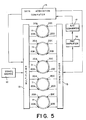
- FIG. 5 A preferred embodiment of a detection apparatus for monitoring a plurality of vials that embodies the principles and concepts of the present invention described above is depicted schematically in FIG. 5.
- the apparatus is preferably comprised of a plurality of sealed glass vials 11 inoculated with a medium/blood mixture, i.e., typical blood culture vials.
- a medium/blood mixture i.e., typical blood culture vials.
- first and second infrared sources 20A,20B are arranged on one side of each vial above the liquid level
- first and second narrow-band infrared detectors 20C,20D are arranged on the otherside of each vial above the liquid level.
- the apparatus made according to the present invention further comprises a DC power supply 12which is connected to the input of a multiplexer 13 which is controlled by a computer 14 to selectively activate the sources and detectors in the manner described above, as well as to sequentially cause such activation to occur vial-to-vial.
- the output channels of the multiplexer 13 are connected to the first and second infrared sources 20A,20B located adjacent each vial 11 and the electrical signal provided by the multiplexer activates the sources 20A,20B.
- the outputs of all the infrared detectors 20C,20D are connected to the inputs of a demultiplexer 15 which is also preferably controlled by the computer 14.
- the demultiplexer 15 functions to coordinate the signals received from the plurality of detector pairs so that the data associated with each vial can be identified.
- the analog output signal of the demultiplexer 15 is fed to the input of a preamplifier 16 and the amplified output signal is preferably digitized by an analog-to-digital converter 17.
- the digital output signal of the analog-to-digital converter 17 is preferably stored in the computer 14 for processing as described above.
- the computer-controlled multiplexer 13 sequentially carries out the steps described above with reference to FIG. 1 on each vial 11 by alternately activating and deactivating the first source 20A and second source 20B.
- the demultiplexer 15 ensures that the data that are related to the individual vials are kept separated and identified when output and stored.
- the system cycles through each vial 11 in the instrument and then begins the process again.
- the presence of bacterial growth will cause a marked increase in the concentration of CO 2 in the headspace gas above the blood/culture sample disposed within each vial 11.
- the data collected by the system depicted in FIG. 5 can therefore be used by either transmitting these data to an operator or by programming the computer 14 to identify those vials 11 exhibiting increased C0 2 concentration.
Abstract
Description
- The present invention relates to a non-invasive methods and apparatus for detecting biological activities in a specimen such as blood by measuring the absorption of light, and in particular to systems wherein the degree of absorption within the gaseous headspace above a specimen and a culture medium contained in a sealed container varies with the concentration of carbon dioxide generated by the metabolic processes of microorganisms.
- Usually, the presence of biologically active agents such as bacteria in a patient's body fluid, and especially in blood, is determined using blood culture vials. A small quantity of blood is injected through an enclosing rubber septum into a sterile vial containing a culture medium. The vial is typically incubated at 37°C and monitored for bacterial growth.
- Common visual inspection involves monitoring the turbidity or observing eventual color changes of the liquid suspension. Known instrumented methods detect changes in the carbon dioxide content of the culture bottles, which is a metabolic byproduct of the bacterial growth. Monitoring the carbon dioxide content can be accomplished by methods well established in the art, such as radiochemical (e.g., BACTEC®, Becton-Dickinson, Franklin Lakes, NJ, USA), infrared absorption at a carbon dioxide spectral line (e.g., NR-BACTEC@, Becton-Dickinson, Franklin Lakes, NJ, USA), or pressure/vacuum measurement such as those disclosed in U.S. Patent No. 4,152,213 -- Ahnell. However, all these methods require invasive procedures which result in the well-known problem of cross-contamination within the vial. For purposes of this application, the term invasive implies that the confines of the sample container must be entered in order to determine if bacteria are present, e.g., a probe is inserted into a sealed vial. In the first two methods mentioned above, the headspace gas must be removed for analysis. In the case ofvacuum/pressure measurement, while pressure is measured in a closed vial, any temperature change within the vial headspace also generates a pressure change that is not related to biological activity.
- Therefore, an additional headspace temperature measurement is required in order to distinguish between biological and temperature-generated pressure effects. Non-invasive headspace temperature monitoring, however, represents a difficult problem, and no practical solutions are at hand. Additionally, some microorganisms can produce high pressure values while others produce relatively low or negligible ones. Thus, any pressure sensors used must be sensitive enough to allow detection of small changes in pressure while also being capable of safely measuring high pressure values. These two requirements are often mutually exclusive depending on the type of pressure sensor technology used. Thus far none of the pressure measurement systems known in the prior art permit the rapid and reliable detection of a wide variety of bacteria.
- In order to circumvent the problems of cross-contamination, a non-invasive infrared microorganism detection instrument has been proposed in which special vials with infrared-transmitting windows are utilized. See U.S. Patent No. 4,889,992 -- Hoberman. These vials, however, are relatively expensive. There is also an instrument in which glass vials are transferred to an infrared spectrometer by an automated manipulator arm and measured through the glass vial. This instrument is known as the BIO AGROS and is distributed by Diagnostics Pasteur, France. The disadvantage of this system is that, due to the high infrared absorption of glass, small changes in the glass wall thickness generate large errors in the measured headspace gas absorption. These problems can be partly reduced by utilizing high-quality glass vials, but this measure results in relatively high vial cost.
- Recently, non-invasive methods have been developed involving chemical sensors disposed inside the vial. These sensors respond to changes in the carbon dioxide concentration by changing their color or by changing their fluorescence intensity. See, e.g., Thorpe, et al. "BacT/Alert: an Automated Colorimetric Microbial Detection System" J. Clin. Microb., July 1990, pp. 1608-12 and U.S. Patent No. 4,945,060. These techniques are based on light intensity measurements and require spectral filtering in the excitation and/or emission signals. This means that errors can occur if any of the light source, the photodetector, the filters, or the sensor show aging effects over time which would vary the intensity response.
- The disadvantage of such intensity-based methods can be overcome by utilizing a modulated excitation signal in combination with fluorescent sensors that change fluorescent their decay time with changing carbon dioxide concentration. In such a device, light intensity measurement is replaced with time measurement, and intensity changes and the related variations in sensor sentivity have no impact upon its operation. However, current fluorescent decay time sensors require high-brightness, short-wavelength light sources (550 nm or shorter) that are intensity-modulated at very high frequencies (typically about 100 MHz). Thus, for example, such a system might use a 5-mW green HeNe laser (543.5 nm), externally modulated by means of an acoustooptic light modulator, the operation of which is understood by those of ordinary skill. However, it will be realized that such a laser/modulator combination is rather expensive, requiring that the samples be moved to the laser, instead of having one light source at each sample. Such an instrument would therefore by necessity have a complicated mechanism for effecting the transportation of the individual samples to the light source and the time interval between successive measurements for each sample would be relatively long. It appears unlikely that high-brightness short-wavelength semiconductor diode lasers will be developed in the near future. Thus, even such an improved system would suffer serious practical shortcomings.
- Thus, there remains an unmet need to provide a system for detecting microorganisms in samples that are sealed in vials that can tolerate the errors caused by the defects found in inexpensive glass vials. It is therefore an object of the present invention to overcome the limitations of the prior art described above by providing methods and apparatus for detecting biological activities in a specimen such as blood that are non-invasive and that do not require chemical sensors or any other additives within the specimen container. It is a further object of this invention to disclose a system that does not require high-brightness, short-wavelength light sources while also providing methods and apparatus that are safe against eventual extreme high pressure values while not being sensitive to headspace temperature changes. Another object of the present invention is to provide a system that is simple and inexpensive, so that each vial can be monitored continuously, thus allowing the construction of diagnostic instruments containing a plurality of stationary vials.
- According to the present invention, the objectives set forth above are achieved by introducing a culture medium and a sample, such as a blood specimen, into a sealable glass vial and arranging a first and a second infrared light source on the side of the vial, positioned above the level of the liquid within the vial and at a fixed distance from each other. By then arranging a first and a second narrow-band infrared detector on the side of the vial approximately opposite the sources and also above the liquid level within the vial, the sources of error are cancelled. In operation, the present invention sequentially measures the photocurrents generated at each detector with no source turned on, with the first source turned on, and with the second source turned on and the first source turned off. The C02 absorption coefficient of the vial headspace gas is then calculated based on the photocurrents measured. This arrangement and measuring procedure allow compensation for source aging, detector aging, and vial wall thickness changes. Moreover, the present invention permits a determination of the absolute absorption coefficient at a selected wavelength, most preferably about 4.26 µm, which is the C02 absorption characteristic wavelength. The determination of the absolute C02 concentration within the headspace permits the detection of bacterial growth processes.
- The present invention therefore provides methods of identifying the presence of biological activity within a sample contained in a vial that comprise the steps of disposing a first and a second source of infrared radiation at adjacent points on the vial and disposing a first and a second infrared detector at adjacent points on the vial that are substantially opposite from the first and second source. Next, the first detector is activated to measure a background signal, lco, and then the first source is activated and an output signal, IcA, is measured with the first detector. The first source is then deactivated and the second source activated to measure an output signal, Ics, with the first detector. The first detector and the second source are deactivated and a background signal, IDO, is measured with the second detector. The second detector is also used to measure an output signal from thefirstand second sources, ISAand IDB. The methods of the present invention then proceed by calculating an absorption value from the background and output signals and repeating the steps of measuring the background and output signals from both the sources and both the detectors to determine further absorption values over time. The absorption values are then compared to determine if biological activity is present.
- In preferred embodiments, the steps of activating and deactivating the sources and the detectors is carried out by a computer, as is the step of determining the absorption value. The step of determining the absorption value preferably comprises calculating the output signals for the first and second detectors as the first and second sources are activated and deactivated; and computing a value R according to the equation:

wherein Ico is the background signal of the first detector and IDO is the background signal of the second detector. The output signal of the first detector with the first source activated is ICA and with the second source activated is Ics. Similarly, the output of he second detector is represented by IDA and IDB for the first and second sources, respectively. - In a most preferred embodiment, the methods of the present invention are carried out to identify the presence of biological activity for a plurality of samples. In such embodiments, the steps of activating and deactivating the first and second sources associated with each of the plurality of samples most preferably comprises transmitting an activation signal to a multiplexer and directing the activation signal to the first and second sources associated with one of the plurality of vials. Similarly, the activation and deactivation of the first and second detectors associated with each of the plurality of samples most preferably comprises the steps of receiving an output signal from a demultiplexer and creating a demultiplexer output signal associated with one of the plurality of vials.
- In an apparatus made according to the present invention, the infrared sources are not modulated and no rotating filter wheel is required. The photocurrents are measured at a relatively low electronic detection bandwidth and preferably stored within a computer. The low detection bandwidth results in a high signal-to-noise ratio for the measured photocurrents. The function commonly accomplished by a mechanical chopper is taken over by the computer. The present invention therefore avoids any mechanically actuated sections. Additionally, the source/detector combination disclosed herein can be produced at low cost. Therefore, each vial preferably has its own source/detector combination, thereby allowing the construction of diagnostic instruments capable of monitoring a plurality of vials at the same time.
- Apparatus for identifying the presence of biological activity within a sample contained in a vial made in accordance with the present invention therefore preferably comprises a first and a second source of infrared radiation disposed at adjacent points on the vial and a first and a second infrared detector disposed at adjacent points on the vial substantially opposite from the second and the first source respectively. A signal source selectively activates and deactivates the sources of infrared radiation. Preferably, a processor calculates an absorption value from an output signal received from at least each of the first and the second detector to permit the detection of biological activity if the absorption value measured is significantly higher than a absorption value measured at a previous point in time.
- Preferably the apparatus of the present invention identifies the presence of biological activity in a plurality of samples. Theses embodiments include a first and second source of infrared radiation associated with each of the plurality of samples; and a signal source for transmitting an activation signal to a multiplexer for selectively directing the activation signal to the first and second sources associated with one of the plurality of samples. The apparatus also preferably comprises a first and second detector associated with each of the plurality of vials; and a demultiplexer for selectively receiving an output signal from the detectors associated with one of the plurality of vials and creating a demultiplexer output signal associated with one of the plurality of vials. In a most preferred embodiment of the apparatus of the present invention, the first and second sources of infrared radiation emit radiation at a wavelength of about 4.26 µm.
-
- FIG. 1 is a top view of a blood culture vial or similar sample container with two infrared sources disposed on one side of the vial and two infrared detectors on the other side.
- FIGS. 2-4 are plots of the theoretical system output signal, R, versus the C02 absorption coefficient, wa, for specific geometrical and spectral conditions for the device illustrated in FIG. 1.
- Fig. 5 is a schematic illustration of an apparatus for detecting microorganisms in a plurality of samples according to the present invention.
- Referring now to FIG. 1 there is shown a top view of a
blood culture vial 11 with a firstinfrared source 20A and a secondinfrared source 20B disposed on one side of the vial, and a first 4.26 f..lm narrow-bandinfrared detector 20C and a second 4.26 µm narrow-bandinfrared detector 20D disposed at two points on the other side. In this particular case, the firstinfrared source 20A and thesecond detector 20D are arranged opposite to each other, as are the secondinfrared source 20B andfirst detector 20C. In a preferred embodiment, the angle between the lines connecting the first source 20Awith thesecond detector 20D, and thesecond source 20B with thefirst detector 20C is between about 20° and about 90°. This arrangement of sources and detectors results in equal optical headspace gas path lengths, i.e., L1=AC=BD and L2=AD=BC, respectively, as shown in FIG. 1. In order to obtain the best results, each source/detector pair should be diametrically opposed, i.e., L1 in FIG. 1 should pass through the geometric center of thevial 11. In general, however, apparatus made according to the present invention is not restricted to the geometrical arrangement depicted in FIG. 1. Additionally, thesources detectors infrared sources detectors - Methods for measuring the absorption coefficient according to the present invention preferably comprise a first step of detecting a background signal when no infrared source is turned on. The background signal, loo, of the
detector 20C is measured and background signal, IDO, of thedetector 20D is also measured. Next, the firstinfrared source 20A is turned on, and the signal, ICA, ofdetector 20C is measured. This signal can be described in the form:
- In equation (1), IA is the infrared power emitted by the first
infrared source 20A, Rc is the responsivity offirst detector 20C, and F is a general geometry factor taking into account such properties as source emission divergence and detector aperture. The quantity k characterizes the spectral fraction of radiation absorbed by C02 molecules relative to the spectral window of the infrared detector. The glass absorption is represented by µ9, and the C02 absorption coefficient is wa. - The thickness of the vial wall at the
first source 20A is denominated by a, and the thickness at thefirst detector 20C by c. The quantities a' and c' in equation (1) are different from a and c, because thefirst source 20A and thefirst detector 20C are not arranged exactly opposite one another, as shown by line L1 in FIG. 1. For a distance, s, between the first andsecond sources - The radiation emitted by the
first source 20A is then measured with thesecond detector 20D. The output signal of thisdetector 20D is:
- Next, the
first source 20A is turned off,source 20B is turned on, and the signal, ICB, of thefirst detector 20C is measured. This signal can be described in the form:
- In equation (3), IB is the infrared power emitted by the
second source 20B. The next step comprises measuring the radiation emitted by thesecond source 20B with thesecond detector 20D. The output signal of this detector is:
- In equation (4) the effective glass path lengths b' and d' are: b' = b/cos β and d'=d/cosβ, respectively, with b and d being the respective wall thicknesses at the
second source 20B and thesecond detector 20D. - All these output signals from the
detectors 
- Using equations (1) to (5), the expression:

- is obtained for the CO2 concentration dependent system output signal, R(µa). Equation (6) shows that the power of the infrared sources IA and IB, the geometry factor F, and the responsivities of the defectors Rc and RD are cancelled out using the'arrangement of sources and detectors described above with reference to FIG. 1. Therefore, the present invention provides a system that does not show any aging drifts related to the
sources detectors - One of ordinary skill in the art will realize that in an apparatus according to the present invention, the infrared sources are not modulated, and no rotating filter wheel is'required. In the prior art, the apparatus response function had been eliminated by comparing an absorption measurement performed at a C02 spectral line with an absorption measurement performed at a wavelength close to a C02 spectral line. Therefore, apparatus such as a rotating filter wheel was commonly used to create signals of two different wavelengths. It is impractical, however, to arrange one filter wheel at each vial or sample container in a device for simultaneously testing hundreds of vials. Alternatively, if one infrared source and two detectors having a different spectral window were used, the glass wall changes near the two detectors would not be canceled out. However, in the preferred embodiments of an apparatus constructed according to the present invention, these variations are canceled out to a high degree, as will be shown below.
- Additionally, in the present invention, the photocurrents are measured at a relatively low electronic detection bandwidth and are preferably stored within a computer. The low detection bandwidth results in a high signal-to-noise ratio for the measured photocurrents. The function of detector background signal discrimination, accomplished in the prior art by a mechanical chopper, is taken over by the computer. This principle avoids any mechanically moving parts and the source/detector combination described above and shown in FIG. 1 can be produced at low cost, permitting each
vial 11 to have its own source/detector combination and allowing the construction of diagnostic instruments capable of processing hundreds of non-moving vials. - In equation (6) set forth above, the quantity q is equal to (1/cos β)-1. For β values up to about 20°, i.e., for a-values up to about 30°, q can be approximated by (1/2)(s/nv)2, and the relation q Z 0.05 is valid. As an example, q = 0.05 for a = 27°, and q = 0.02 for a = 18°. This means that changes in the vial wall thickness have a much smaller effect as compared to a standard detector. In other words, a typical low-cost vial with a wall thickness variation of ± 0.5 mm is transformed into a high-quality vial with an effective wall thickness variation of ± 25 µm -- an improvement by a factor of 20.
- The operation and advantages of apparatus made according to the present invention can be illustrated more clearly by calculating the relative error in the system output signal, R(wa), caused by a variation in the wall thickness of the sample vial. For a device with only one source and one detector, equation (2) is used to obtain the relation:

- For an apparatus according to the present invention, equation (7) is used to obtain the relation:

- Comparison of equations (7) and (8) shows that the relative error in an apparatus according to the present invention is reduced significantly because q « 1. In equation (2), two glass wall contributions are effective. In equation (7) this number is doubled. In practice, however, a partial cancellation of the four variations can be expected because the glass wall variations are likely to be a mixture of positive and negative ones.
- As mentioned above, the quantity k in equation (6) characterizes the spectral fraction of radiation absorbed by C02 molecules, relative to the spectral window of the
infrared detectors - FIG. 2 shows R versus µa for a vial with an inner diameter v = 39 mm (e.g., a standard BACTEC@ vial supplied by Becton Dickinson Diagnostic Instrument Systems, Sparks, Maryland), and with a distance s = 19 mm between
infrared sources - FIG. 3 shows a plot of R(wa) under conditions similar to those in FIG. 2, but assuming lower k-values, between 0.5 and 0.8. The lower k-values result from usage of
infrared detectors - FIG. 4 shows a plot of R versus µa for a vial with a smaller inner diameter than the vial for which the data in FIGS. 2-3 were derived. The vial used in FIG. 4 has an inner diameter v = 30 mm, and a distance s = 18 mm between
infrared sources - The arrangement and measuring procedures described above allow for the compensation of source aging, detector aging, and vial-to-vial wall thickness variations. If a typical vial wall thickness a = b = c = d = 2.5 mm is assumed, along with a glass absorption coefficient µa = 5 cm-1 and q = 0.02, then the pre-factor exp[- q(a+b+c+d)µ9] in equation (6) becomes about 0.9. If it is also assumed, as a worst case scenario, that all wall thicknesses, a, b, c, and d, have the same vial-to-vial variation (amount and sign) of ± 0.5 mm, then for the relative variation in the system output signal, dR/R, a value of± 2% is obtained. This means that an apparatus according to the present invention permits the determination of the absolute value of µa within the vial headspace. Therefore, a determination of the absolute C02 concentration within the headspace is possible if the filter-related k-factor is known. In other words, despite using low-cost vials, a threshold for R can be set in order to distinguish positive vials exhibiting biological activity from negative ones. Finally, it should be noted that for a single vial the vial-to-vial variations -- da, db, dc, and dd have little or no impact on the time course of R(t). Taking into consideration the total source intensity and detector responsivity compensation, small changes in the C02 concentration will therefore be detectable.
- A preferred embodiment of a detection apparatus for monitoring a plurality of vials that embodies the principles and concepts of the present invention described above is depicted schematically in FIG. 5. The apparatus is preferably comprised of a plurality of sealed
glass vials 11 inoculated with a medium/blood mixture, i.e., typical blood culture vials. As discussed above with reference to FIG. 1, first and secondinfrared sources infrared detectors multiplexer 13 which is controlled by acomputer 14 to selectively activate the sources and detectors in the manner described above, as well as to sequentially cause such activation to occur vial-to-vial. The output channels of themultiplexer 13 are connected to the first and secondinfrared sources vial 11 and the electrical signal provided by the multiplexer activates thesources infrared detectors demultiplexer 15 which is also preferably controlled by thecomputer 14. Thedemultiplexer 15 functions to coordinate the signals received from the plurality of detector pairs so that the data associated with each vial can be identified. The analog output signal of thedemultiplexer 15 is fed to the input of apreamplifier 16 and the amplified output signal is preferably digitized by an analog-to-digital converter 17. The digital output signal of the analog-to-digital converter 17 is preferably stored in thecomputer 14 for processing as described above. - In operation, the computer-controlled
multiplexer 13 sequentially carries out the steps described above with reference to FIG. 1 on eachvial 11 by alternately activating and deactivating thefirst source 20A andsecond source 20B. Thedemultiplexer 15 ensures that the data that are related to the individual vials are kept separated and identified when output and stored. The system cycles through eachvial 11 in the instrument and then begins the process again. As noted above, the presence of bacterial growth will cause a marked increase in the concentration of CO2 in the headspace gas above the blood/culture sample disposed within eachvial 11. The data collected by the system depicted in FIG. 5 can therefore be used by either transmitting these data to an operator or by programming thecomputer 14 to identify thosevials 11 exhibiting increased C02 concentration. - Although certain embodiments of the present invention have been set forth with particularity, these embodiments are for the purposes of illustrating the present invention and are not meant to be limiting. As will be readily understood by those of ordinary skill numerous variations, modifications and adaptations of the concepts disclosed herein are possible. For example, the samples are not limited to blood/culture samples, nor are the detectors meant to be limited to the detection of C02 concentration alone. As discussed above, the geometry of the sources and detectors can be varied while still achieving useful results. Therefore, in order to determine the full scope of the present invention, reference should be made to the appended claims.
Claims (10)

Applications Claiming Priority (2)
| Application Number | Priority Date | Filing Date | Title |
|---|---|---|---|
| US87423992A | 1992-04-24 | 1992-04-24 | |
| US874239 | 1992-04-24 |
Publications (2)
| Publication Number | Publication Date |
|---|---|
| EP0567230A2 true EP0567230A2 (en) | 1993-10-27 |
| EP0567230A3 EP0567230A3 (en) | 1995-04-26 |
Family
ID=25363295
Family Applications (1)
| Application Number | Title | Priority Date | Filing Date |
|---|---|---|---|
| EP93302291A Ceased EP0567230A3 (en) | 1992-04-24 | 1993-03-25 | Methods and apparatus for detecting microorganisms in blood culture vials. |
Country Status (6)
| Country | Link |
|---|---|
| US (1) | US5482842A (en) |
| EP (1) | EP0567230A3 (en) |
| JP (1) | JPH0777560B2 (en) |
| AU (1) | AU665246B2 (en) |
| BR (1) | BR9301589A (en) |
| CA (1) | CA2092372C (en) |
Cited By (3)
| Publication number | Priority date | Publication date | Assignee | Title |
|---|---|---|---|---|
| AU702209B2 (en) * | 1996-07-16 | 1999-02-18 | Roche Diagnostics Gmbh | Analytical system with means for detecting too small sample volumes |
| WO1999060094A2 (en) * | 1998-05-20 | 1999-11-25 | Forschungszentrum Jülich GmbH | Method for measuring the interaction of chemicals with cells |
| EP2250501B1 (en) * | 2007-12-07 | 2016-02-24 | Diesse Diagnostica Senese S.p.a. | Device and method for microbiological analysis of biological samples |
Families Citing this family (16)
| Publication number | Priority date | Publication date | Assignee | Title |
|---|---|---|---|---|
| US6573991B1 (en) | 2000-04-26 | 2003-06-03 | Martin Paul Debreczeny | Self-compensating radiation sensor with wide dynamic range |
| US6639678B1 (en) * | 2000-07-13 | 2003-10-28 | Lighthouse Instruments Llc | Apparatus and method for nondestructive monitoring of gases in sealed containers |
| US7427501B2 (en) * | 2000-09-29 | 2008-09-23 | Becton, Dickinson And Company | System and method for optically monitoring the concentration of a gas, or the pressure, in a sample vial to detect sample growth |
| JP2004522960A (en) * | 2001-02-02 | 2004-07-29 | ブリストル−マイヤーズ・スクイブ・ファーマ・カンパニー | Apparatus and method for online monitoring of fluorinated material in vial headspace |
| US6709857B2 (en) * | 2001-06-26 | 2004-03-23 | Becton, Dickinson And Company | System and method for optically monitoring the concentration of a gas in a sample vial using photothermal spectroscopy to detect sample growth |
| US7126685B1 (en) | 2003-01-02 | 2006-10-24 | Southwest Sciences Incorporated | Optical absorbance sensitivity and reliability improvement via rotation of sample container |
| US7334482B2 (en) * | 2004-07-20 | 2008-02-26 | Martin Lehmann | Method of monitoring pressure of a gas species and apparatus to do so |
| CA2585200A1 (en) * | 2004-10-21 | 2006-05-04 | Peter E. Rising | Infrared measurement for the rapid enumeration of microbial concentrations |
| EP2392643B1 (en) * | 2009-01-29 | 2016-10-26 | Hitachi High-Technologies Corporation | Device and method for automatically analyzing bacteria and fungi |
| CN105462826B (en) * | 2010-07-20 | 2018-01-12 | 生物梅里埃有限公司 | The detector assembly of flashing lightning magnetic field detector with colorimetric sensor |
| CN102590137A (en) * | 2011-12-19 | 2012-07-18 | 浙江师范大学 | System for detecting blood culture instrument |
| US9176050B2 (en) | 2012-05-03 | 2015-11-03 | Lighthouse Instruments, Llc. | Method and apparatus for increased purge efficacy in optical absorption spectroscopic measurements of gases in sealed containers |
| US20150099274A1 (en) | 2012-06-17 | 2015-04-09 | Physical Logic Ag | Method and system for use in monitoring biological material |
| US9441260B2 (en) | 2012-06-17 | 2016-09-13 | Vayu Sense Ag | Method and system for real-time, non-invasive monitoring of a biological material in a sealed container |
| WO2014049831A1 (en) * | 2012-09-28 | 2014-04-03 | ニプロ株式会社 | Device for measuring and method for measuring fluid concentration |
| JP2018119894A (en) * | 2017-01-27 | 2018-08-02 | 日立造船株式会社 | Laser spectroscopy inspection method and laser spectroscopy inspection device |
Citations (5)
| Publication number | Priority date | Publication date | Assignee | Title |
|---|---|---|---|---|
| EP0104463A1 (en) * | 1982-08-31 | 1984-04-04 | Becton Dickinson and Company | Detection of the presence of biological activity utilizing infrared analysis |
| US4448534A (en) * | 1978-03-30 | 1984-05-15 | American Hospital Corporation | Antibiotic susceptibility testing |
| US4456380A (en) * | 1980-08-01 | 1984-06-26 | Fujisawa Pharmaceutical Co., Ltd. | Test system for identifying bacteria |
| SU1366922A1 (en) * | 1985-05-15 | 1988-01-15 | Казанский Научно-Исследовательский Технологический И Проектный Институт Химико-Фотографической Промышленности | Nephelometer |
| CH681747A5 (en) * | 1992-06-02 | 1993-05-14 | Zuellig Ag |
Family Cites Families (8)
| Publication number | Priority date | Publication date | Assignee | Title |
|---|---|---|---|---|
| US3975727A (en) * | 1974-06-28 | 1976-08-17 | Technicon Instruments Corporation | Automated calibration and standardization apparatus |
| US4017193A (en) * | 1976-03-02 | 1977-04-12 | Leo Loiterman | Apparatus for measuring the transmittance or opacity of a gaseous medium carrying particulate matter through a conduit |
| US4152213A (en) * | 1977-03-10 | 1979-05-01 | Johnston Laboratories, Inc. | Vacuum detection of bacteria |
| US5155019A (en) * | 1982-08-31 | 1992-10-13 | Becton, Dickinson And Company | Detection of the presence of biological activity in a sealed container utilizing infrared analysis of carbon dioxide and apparatus therefor |
| US4971900A (en) * | 1984-04-06 | 1990-11-20 | Becton, Dickinson And Company | Method for the detection of biologically active agents |
| US4889992A (en) * | 1987-11-12 | 1989-12-26 | Max Hoberman | Automatic infrared microorganism detection instrument |
| US4945060A (en) * | 1988-03-15 | 1990-07-31 | Akzo N. V. | Device for detecting microorganisms |
| AU645557B2 (en) * | 1990-05-07 | 1994-01-20 | University Of Sydney, The | Gas detection by infrared absorption |
-
1993
- 1993-03-24 CA CA002092372A patent/CA2092372C/en not_active Expired - Fee Related
- 1993-03-25 EP EP93302291A patent/EP0567230A3/en not_active Ceased
- 1993-04-16 AU AU37002/93A patent/AU665246B2/en not_active Ceased
- 1993-04-19 BR BR9301589A patent/BR9301589A/en not_active IP Right Cessation
- 1993-04-26 JP JP5099608A patent/JPH0777560B2/en not_active Expired - Lifetime
-
1994
- 1994-04-07 US US08/224,054 patent/US5482842A/en not_active Expired - Lifetime
Patent Citations (5)
| Publication number | Priority date | Publication date | Assignee | Title |
|---|---|---|---|---|
| US4448534A (en) * | 1978-03-30 | 1984-05-15 | American Hospital Corporation | Antibiotic susceptibility testing |
| US4456380A (en) * | 1980-08-01 | 1984-06-26 | Fujisawa Pharmaceutical Co., Ltd. | Test system for identifying bacteria |
| EP0104463A1 (en) * | 1982-08-31 | 1984-04-04 | Becton Dickinson and Company | Detection of the presence of biological activity utilizing infrared analysis |
| SU1366922A1 (en) * | 1985-05-15 | 1988-01-15 | Казанский Научно-Исследовательский Технологический И Проектный Институт Химико-Фотографической Промышленности | Nephelometer |
| CH681747A5 (en) * | 1992-06-02 | 1993-05-14 | Zuellig Ag |
Non-Patent Citations (2)
| Title |
|---|
| SOVIET INVENTIONS ILLUSTRATED Section Ch, Week 8831, Derwent Publications Ltd., London, GB; Class H05, AN 88-219154 & SU-A-1 366 922 (KAZAN CHEM PHOTO IN) 15 January 1988 * |
| TECHNISCHE RUNDSCHAU, 1 FEB. 1977, SWITZERLAND, VOL. 69, NO. 5, PAGES 9 - 10, ISSN 0040-148X Landbeck R 'Measurements in sewage plant' * |
Cited By (4)
| Publication number | Priority date | Publication date | Assignee | Title |
|---|---|---|---|---|
| AU702209B2 (en) * | 1996-07-16 | 1999-02-18 | Roche Diagnostics Gmbh | Analytical system with means for detecting too small sample volumes |
| WO1999060094A2 (en) * | 1998-05-20 | 1999-11-25 | Forschungszentrum Jülich GmbH | Method for measuring the interaction of chemicals with cells |
| WO1999060094A3 (en) * | 1998-05-20 | 2000-03-16 | Forschungszentrum Juelich Gmbh | Method for measuring the interaction of chemicals with cells |
| EP2250501B1 (en) * | 2007-12-07 | 2016-02-24 | Diesse Diagnostica Senese S.p.a. | Device and method for microbiological analysis of biological samples |
Also Published As
| Publication number | Publication date |
|---|---|
| CA2092372C (en) | 2000-03-14 |
| EP0567230A3 (en) | 1995-04-26 |
| CA2092372A1 (en) | 1993-10-25 |
| JPH0670794A (en) | 1994-03-15 |
| AU3700293A (en) | 1993-10-28 |
| JPH0777560B2 (en) | 1995-08-23 |
| AU665246B2 (en) | 1995-12-21 |
| US5482842A (en) | 1996-01-09 |
| BR9301589A (en) | 1993-10-26 |
Similar Documents
| Publication | Publication Date | Title |
|---|---|---|
| US5427920A (en) | Methods and apparatus for detecting biological activities in a specimen | |
| US5482842A (en) | Methods for detecting microorganisms in blood culture vials | |
| JP2738500B2 (en) | Equipment for measuring biological activity in culture vessels | |
| US5422720A (en) | Blood culture sensor station utilizing two distinct light sources | |
| CA2101886C (en) | Method and apparatus for detecting microorganisms | |
| CA2179364C (en) | Method and apparatus for detecting microorganisms | |
| US5266486A (en) | Method and apparatus for detecting biological activities in a specimen | |
| AU667884B2 (en) | Detection of bacteria in blood culture bottles by time-resolved light scattering and absorption measurement | |
| EP0448923B1 (en) | Method and apparatus for detecting biological activities in a specimen | |
| EP2596118B1 (en) | Detector arrangement for blood culture bottles with colorimetric sensors | |
| JP2674736B2 (en) | Method and apparatus for analyzing emitted light from a fluorescent chemical sensor | |
| EP0697460B1 (en) | Optical blood culture sensor | |
| US4013368A (en) | Sample cartridge for use in apparatus for evaluation of biological fluid | |
| AU706915B2 (en) | Multiple sample container | |
| CA2208597A1 (en) | Device for measuring the partial pressure of gases dissolved in liquids | |
| US3983006A (en) | Method for determining minimum inhibitory concentration of antibiotic | |
| US3938049A (en) | Baseline correction system for pulse trains | |
| USRE28800E (en) | Apparatus for evaluation of biological fluid |
Legal Events
| Date | Code | Title | Description |
|---|---|---|---|
| PUAI | Public reference made under article 153(3) epc to a published international application that has entered the european phase |
Free format text: ORIGINAL CODE: 0009012 |
|
| AK | Designated contracting states |
Kind code of ref document: A2 Designated state(s): DE ES FR GB IT SE |
|
| PUAL | Search report despatched |
Free format text: ORIGINAL CODE: 0009013 |
|
| AK | Designated contracting states |
Kind code of ref document: A3 Designated state(s): DE ES FR GB IT SE |
|
| 17P | Request for examination filed |
Effective date: 19951023 |
|
| 17Q | First examination report despatched |
Effective date: 19980724 |
|
| RTI1 | Title (correction) |
Free format text: METHODS FOR DETECTING MICROORGANISMS IN BLOOD CULTURE VIALS |
|
| GRAG | Despatch of communication of intention to grant |
Free format text: ORIGINAL CODE: EPIDOS AGRA |
|
| STAA | Information on the status of an ep patent application or granted ep patent |
Free format text: STATUS: THE APPLICATION HAS BEEN REFUSED |
|
| 18R | Application refused |
Effective date: 20010329 |