EP0566298B1 - Sheet decurling system - Google Patents
Sheet decurling system Download PDFInfo
- Publication number
- EP0566298B1 EP0566298B1 EP19930302666 EP93302666A EP0566298B1 EP 0566298 B1 EP0566298 B1 EP 0566298B1 EP 19930302666 EP19930302666 EP 19930302666 EP 93302666 A EP93302666 A EP 93302666A EP 0566298 B1 EP0566298 B1 EP 0566298B1
- Authority
- EP
- European Patent Office
- Prior art keywords
- sheet
- decurler
- decurling
- ambient air
- belts
- Prior art date
- Legal status (The legal status is an assumption and is not a legal conclusion. Google has not performed a legal analysis and makes no representation as to the accuracy of the status listed.)
- Expired - Lifetime
Links
- 239000012080 ambient air Substances 0.000 claims description 26
- 239000000463 material Substances 0.000 description 18
- 239000000843 powder Substances 0.000 description 6
- 239000003570 air Substances 0.000 description 5
- 239000004699 Ultra-high molecular weight polyethylene Substances 0.000 description 4
- 229920002635 polyurethane Polymers 0.000 description 4
- 239000004814 polyurethane Substances 0.000 description 4
- 229920000785 ultra high molecular weight polyethylene Polymers 0.000 description 4
- DHKHKXVYLBGOIT-UHFFFAOYSA-N 1,1-Diethoxyethane Chemical compound CCOC(C)OCC DHKHKXVYLBGOIT-UHFFFAOYSA-N 0.000 description 2
- 239000011354 acetal resin Substances 0.000 description 2
- 239000006185 dispersion Substances 0.000 description 2
- 230000007935 neutral effect Effects 0.000 description 2
- 229920006324 polyoxymethylene Polymers 0.000 description 2
- 239000012530 fluid Substances 0.000 description 1
- 238000004519 manufacturing process Methods 0.000 description 1
- 238000000034 method Methods 0.000 description 1
- 230000003134 recirculating effect Effects 0.000 description 1
Images





Classifications
-
- B—PERFORMING OPERATIONS; TRANSPORTING
- B65—CONVEYING; PACKING; STORING; HANDLING THIN OR FILAMENTARY MATERIAL
- B65H—HANDLING THIN OR FILAMENTARY MATERIAL, e.g. SHEETS, WEBS, CABLES
- B65H29/00—Delivering or advancing articles from machines; Advancing articles to or into piles
- B65H29/70—Article bending or stiffening arrangements
-
- B—PERFORMING OPERATIONS; TRANSPORTING
- B65—CONVEYING; PACKING; STORING; HANDLING THIN OR FILAMENTARY MATERIAL
- B65H—HANDLING THIN OR FILAMENTARY MATERIAL, e.g. SHEETS, WEBS, CABLES
- B65H23/00—Registering, tensioning, smoothing or guiding webs
- B65H23/04—Registering, tensioning, smoothing or guiding webs longitudinally
- B65H23/34—Apparatus for taking-out curl from webs
-
- B—PERFORMING OPERATIONS; TRANSPORTING
- B65—CONVEYING; PACKING; STORING; HANDLING THIN OR FILAMENTARY MATERIAL
- B65H—HANDLING THIN OR FILAMENTARY MATERIAL, e.g. SHEETS, WEBS, CABLES
- B65H2301/00—Handling processes for sheets or webs
- B65H2301/50—Auxiliary process performed during handling process
- B65H2301/51—Modifying a characteristic of handled material
- B65H2301/512—Changing form of handled material
- B65H2301/5125—Restoring form
- B65H2301/51256—Removing waviness or curl, smoothing
Definitions
- This invention relates generally to an apparatus for improving the quality of a sheet, and more particularly concerns a sheet decurling system.
- a curl or bend may be created in a sheet as a result of its method of manufacture.
- a problem which sometimes occurs in a printing machine such as an electrophotographic printing machine is the development of a curl or bend in the sheet as the sheet passes through the various processing stations of the printing machine.
- a curled sheet may be undesirable from a variety of standpoints.
- the curled sheet may be difficult to handle as the sheet is processed in a printing machine. Curled sheets may tend to produce jams or misfeeds within the printing machine. Additionally, sheets having a curl or bend therein may be esthetically undesirable to consumers thereof
- FR-A-2 332 938 (corresponding to US-A-4 055 340) discloses an assisted pneumatic, which corresponds to the preamble of claim 1, transport and registration apparatus in which a stop having a plurality of ports covers an end of a bent rectangular sleeve.
- the sleeve includes at each of two bends a pair of oppositely disposed openings, a driven roller, a drive roller cooperating with the driven roller to provide a nip in the sleeve, and a pair of shrouds covering the rollers and openings.
- a nozzle coupled to a pump provides a flow of air into into the other end of the sleeve and ther air exits through the ports in the stop. The fluid flow is used to bring the rectangular sheets into registration with the stop, the rollers assisting movement of sheets around the bends.
- the present invention provides a system for decurling a sheet which is being advanced in a predetermined path within a machine, comprising: means for generating and directing a flow of room ambient air onto the sheet; a decurler adapted to apply mechanical force to the sheet after the flow of room ambient air has been directed onto the sheet by said generating and directing means; characterised by further including means for controlling said decurler to adjust the mechanical force being applied to the sheet so as to correct curl in the sheet in either one direction or in another direction opposed thereto.
- the generating and directing means is adapted to direct one portion of the flow of room ambient air onto one side of the sheet through the aperture in said first plate and the other portion of the flow of room ambient air onto the other side of the sheet through the aperture in said second plate.
- the generating and directing means comprises means for substantially isolating the flow of room ambient air from machine ambient air prior to the directing of the flow of room ambient air onto the sheet.
- FIG. 1 of the drawings there is shown a printing machine, generally indicated by the reference numeral 5.
- the printing machine may be an electrophotographic printing machine such as the printing machine described in US-A-5,075,734.
- the printing machine 5 includes a fuser apparatus 10, a catch tray 12 and a sheet decurling system, indicated generally by the reference numeral 14.
- the sheet decurling system 14 includes an equilibrium station, indicated generally by the reference numeral 16, and a belt decurling mechanism, indicated generally by the reference numeral 18.
- the decurling system 14 receives a sheet 20, traveling in the direction of arrow 22, from the output of the fuser apparatus 10.
- the decurling system 14 then physically acts on the sheet to reduce the amount of curl therein and subsequently guides the sheet to the catch tray 12 for subsequent removal therefrom by a machine operator.
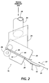
- the equilibrium station 16 is shown in more detail in FIGS. 2-5.
- the equilibrium station 16 includes a fan 34 for producing a current or flow of air.
- the fan 34 is schematically illustrated by a tube in FIGS. 1-3.
- the fan 34 has an intake port 36 positioned to receive ambient air directly from a location outside of the printing machine 5 (also see FIGS. 1-3).
- the intake port may be positioned adjacent an outer wall of the printing machine 5 or the port may extend beyond an outer wall of the printing machine.
- Ambient air located outside of the walls of a printing machine has significantly different characteristics, such as temperature and relative humidity levels, in comparison to ambient air located inside of the walls of a printing machine.
- the equilibrium station 16 further includes a connection duct 24, an upper plenum duct 26 and a lower plenum duct 28.
- the upper plenum duct 26 includes a plate 30 while the lower plenum duct 28 includes a plate 32.
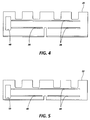
- plate 30 is a number of elongated apertures 38 and an air passageway 48 (see FIG. 4).
- plate 32 has a number of elongated apertures 40 and an air passageway 50 defined therein (see FIG. 5).
- the upper plenum duct 26 receives a flow of room ambient air via the fan 34 and the connection duct 24.
- the lower plenum duct 28 receives a flow of room ambient air via the fan 34, the connection duct 24 and passageways 48 and 50.
- the flow of room ambient air received within upper plenum duct 26 exits through apertures 38 defined in plate 30.
- the flow of room ambient air received within lower plenum duct 28 exits through apertures 40 defined in plate 32.
- the sheet 20 is advanced in the direction of arrow 22, the sheet is guided by a guide member 42 into a space 44 defined between plate 30 and plate 32 (see FIG. 2).
- the equilibrium station 16 further includes a pair of rollers 46 which assists in the advancement of the sheet 20 through the equilibrium station.
- the belt decurling mechanism 18 is shown in more detail in FIGS. 6-14. More specifically, the belt decurling mechanism 18 includes a first set of decurler belts 52 and a second set of decurler belts 54.
- the first set of decurler belts 52 are entrained about a first belt shaft 56 and a second belt shaft 58.
- the second set of decurler belts 54 are entrained about a third belt shaft 60 and a fourth belt shaft 62.
- Belt shafts 56, 58, 60 and 62 are each mounted between a pair of side plates 64 and 66.
- a motor 68 is secured adjacent to the sideplate 66 (see FIG. 7) and mechanically coupled to the first belt shaft 56 by a drive belt 70.
- the first belt shaft 56 is mechanically coupled to the third belt shaft 60 by a set of gears (not shown).
- the motor 68 rotates the drive belt 70
- the first belt shaft 56 and consequently the third belt shaft 60 are caused to rotate.
- each of the decurler belts 52 and each of the decurler belts 54 are caused to advance in a recirculating path of movement.
- the belt decurling mechanism 18 further includes an inlet baffle 63 and an outlet baffle 65.
- the decurler belts 52 and 54 are shown in more detail in Figures 8 and 9.
- the decurler belts 52 are each made from a polyurethane material.
- an inner surface portion 74 of each of the decurler belts 52 comprises a polyurethane material.
- molded in an outer surface portion 76 of each of the decurler belts 52 is a dispersion of fine powder material.
- the fine powder material is an ultra high molecular weight polyethylene material.
- each of the decurler belts 52 comprises a fine powder material such as an ultra high molecular weight polyethylene material
- the frictional resistance between the outer surface portion 76 of each of the decurler belts 52 and the sheet 20 is reduced during advancement of the sheet through the belt decurling mechanism 18.
- the decurler belts 54 are each made from a polyurethane material.
- an inner surface portion 78 of each of the decurler belts 54 comprises a polyurethane material.
- molded in an outer surface portion 80 of each of the decurler belts 54 is a dispersion of fine powder material.
- the fine powder material comprises an ultra high molecular weight polyethylene material.
- each of the decurler belts 54 comprises a fine powder material such as an ultra high molecular weight polyethylene material
- the frictional resistance between the outer surface portion 80 of each of the decurler belts 54 and the sheet 20 is reduced during advancement of the sheet through the belt decurling mechanism 18.
- the sheet is advanced between the outer surface portion 76 of each of the decurler belts 52 and the outer surface portion 80 of each of the decurler belts 54.
- the belt decurling mechanism 18 additionally includes a movable assembly, generally indicated by the reference numeral 72.
- the movable assembly 72 is slidably mounted between sideplates 64 and 66.
- An elongated slot 74' is defined in sideplate 64 while a similar elongated slot (not shown) is defined in sideplate 66.
- the movable assembly 72 is selectively positionable at one of a number of positions along the length of the elongated slots as indicated by the two headed arrow 73 in FIG. 6.
- the printing machine 5 may be equipped with a mechanism (not shown) which allows the machine operator to manually adjust the movable assembly 72 to a desired position or the printing machine may incorporate a mechanism (not shown), including a control system, which automatically adjusts the movable assembly to a desirable position in response to various sensed characteristics of the sheet such as the magnitude of curl in the sheet, the amount of toner on the sheet, and the size and orientation of the sheet.
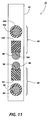
- the movable assembly 72 is shown in more detail in FIGS. 10 and 11.
- the movable assembly includes a pair of end blocks 82. Mounted between the end blocks 82 is a first decurler shaft 84 and a second decurler shaft 86.
- the first support assembly 88 includes a support beam 92 and a support shaft 94.
- the support beam 92 is made of an acetal resin material.
- the support beam 92 can be made from DelrinAF, a trademark of E.I. du Pont de Nemours & Co., Inc. of Wilmington, Delaware.
- the support beam 92 defines a bearing surface 96 which is positioned to contact the first decurler shaft 84.
- the first support beam 92 is also positioned to contact the support shaft 94 (see FIG. 10).
- the first support assembly 88 also includes a number of cylindrical bearings 98, each being positioned around a portion of the support shaft 94 (see FIGS. 7 and 10).
- the cylindrical bearings 98 are caused to rotate around support shaft 94 when the decurler belts 54 are being advanced and are respectively positioned in contact with the cylindrical bearings 98.
- the second support assembly 90 includes a support beam 100 and a support shaft 102.
- the support beam 100 is made of an acetal resin material.
- the support beam 100 can be made from DelrinAF, a trademark of E.I. du Pont de Nemours & Co., Inc. of Wilmington, Delaware.
- the support beam 100 defines a bearing surface 104 which is positioned to contact the second decurler shaft 86.
- the support beam 100 is also positioned to contact the support shaft 102 (see FIG. 10).
- the second support assembly 90 also includes a number of cylindrical bearings 106, each being positioned around a portion of the support shaft 102 (see FIGS. 7 and 10). The cylindrical bearings 106 are caused to rotate around support shaft 102 when the decurler belts 52 are being advanced and are respectively positioned in contact with the cylindrical bearings 106.
- An arcuate portion or region of the first decurler shaft 84 is positionable to contact the inner surface portion 78 of each of the decurler belts 54 while an arcuate portion or region of the second decurler shaft 86 is positionable to contact the inner surface portion 74 of each of the decurler belts 52.
- the decurler belts 52 and the decurler belts 54 each travel through the space defined between the first decurler shaft 84 and the second decurler shaft 86 (see FIGS. 1, 6 and 10-14). Therefore, as the movable assembly 72 is linearly adjusted to one of a variety of positions, as shown in FIGS. 12-14, the sheet path through the belt decurling mechanism 18 is correspondingly adjusted.
- a discrete amount of mechanical force may be applied to the sheet within a range of amounts of mechanical force in either the positive or the negative direction as the sheet is advanced through the nip defined by the area of contact between the outer surface portion 76 of each of the decurler belts 52 and the outer surface portion 80 of each of the of decurler belts 54.
- each of the decurler belts 54 are positioned in contact with an arcuate portion of the first decurler shaft 84 while each of the decurler belts 52 are respectively positioned in contact with the decurler belts 54 and are bent around the arcuate portion of the first decurler shaft 84.
- each of the decurler belts 52 are positioned in contact with an arcuate portion of the second decurler shaft 86 while each of the decurler belts 54 are respectively positioned in contact with the decurler belts 52 and are bent around the arcuate portion of the second decurler shaft 86.
- a strip of flexible material may be positioned near the sheet path between each set of neighboring decurler belts 52, and also between each set of neighboring decurler belts 54.
- Each strip of flexible material would extend from the inlet baffle 63 to the outlet baffle 65 and through the space defined between the first decurler shaft 84 and the second decurler shaft 86.
Landscapes
- Engineering & Computer Science (AREA)
- Mechanical Engineering (AREA)
- Separation, Sorting, Adjustment, Or Bending Of Sheets To Be Conveyed (AREA)
- Delivering By Means Of Belts And Rollers (AREA)
- Paper Feeding For Electrophotography (AREA)
- Registering, Tensioning, Guiding Webs, And Rollers Therefor (AREA)
Description
- This invention relates generally to an apparatus for improving the quality of a sheet, and more particularly concerns a sheet decurling system.
- A curl or bend may be created in a sheet as a result of its method of manufacture. In addition, a problem which sometimes occurs in a printing machine such as an electrophotographic printing machine is the development of a curl or bend in the sheet as the sheet passes through the various processing stations of the printing machine.
- A curled sheet may be undesirable from a variety of standpoints. For instance, the curled sheet may be difficult to handle as the sheet is processed in a printing machine. Curled sheets may tend to produce jams or misfeeds within the printing machine. Additionally, sheets having a curl or bend therein may be esthetically undesirable to consumers thereof
- FR-A-2 332 938 (corresponding to US-A-4 055 340) discloses an assisted pneumatic, which corresponds to the preamble of
claim 1, transport and registration apparatus in which a stop having a plurality of ports covers an end of a bent rectangular sleeve. The sleeve includes at each of two bends a pair of oppositely disposed openings, a driven roller, a drive roller cooperating with the driven roller to provide a nip in the sleeve, and a pair of shrouds covering the rollers and openings. A nozzle coupled to a pump provides a flow of air into into the other end of the sleeve and ther air exits through the ports in the stop. The fluid flow is used to bring the rectangular sheets into registration with the stop, the rollers assisting movement of sheets around the bends. - The present invention provides a system for decurling a sheet which is being advanced in a predetermined path within a machine, comprising: means for generating and directing a flow of room ambient air onto the sheet; a decurler adapted to apply mechanical force to the sheet after the flow of room ambient air has been directed onto the sheet by said generating and directing means; characterised by further including means for controlling said decurler to adjust the mechanical force being applied to the sheet so as to correct curl in the sheet in either one direction or in another direction opposed thereto.
- Preferably, the generating and directing means is adapted to direct one portion of the flow of room ambient air onto one side of the sheet through the aperture in said first plate and the other portion of the flow of room ambient air onto the other side of the sheet through the aperture in said second plate.
- Preferably, the generating and directing means comprises means for substantially isolating the flow of room ambient air from machine ambient air prior to the directing of the flow of room ambient air onto the sheet.
- Other features of the present invention will become apparent as the following description proceeds and upon reference to the drawings, in which:
- FIG. 1 is a schematic elevational view showing a sheet decurling system of a printing machine incorporating the features of the present invention therein;
- FIG. 2 is a schematic side elevational view showing further details of the equilibrium station used in the sheet decurling system of FIG. 1;
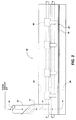
- FIG. 3 is a schematic front elevational view of the equilibrium station of FIG. 2;
- FIG. 4 is a schematic planar view showing the plate of the upper plenum duct of the equilibrium station of FIG. 2;
- FIG. 5 is a schematic planar view showing the plate of the lower plenum duct of the equilibrium station of FIG. 2;
- FIG. 6 is a schematic side elevational view showing further details of the belt decurling mechanism used in the sheet decurling system of FIG. 1;
- FIG. 7 is a schematic front elevational view of the belt decurling mechanism of FIG. 6 with the inlet baffle removed for clarity of description;
- FIG. 8 is a fragmentary sectional view of one belt of the first set of decurling belts of the belt decurling mechanism of FIG. 6;
- FIG. 9 is a fragmentary sectional view of one belt of the second set of decurling belts of the belt decurling mechanism of FIG. 6;
- FIG. 10 is a front elevational view of the movable assembly of the belt decurling mechanism of FIG. 6;
- FIG. 11 is a sectional elevational view taken in the direction of arrows 11-11 of FIG. 10 of the movable assembly of FIG. 6;
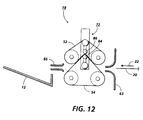
- FIG. 12 is a schematic elevational view of a part of the belt decurling mechanism of FIG. 6 showing the movable assembly positioning the first set of decurling belts and the second set of decurling belts to thereby define a path through which the sheet may be advanced;
- FIG. 13 is a schematic elevational view of a part of the belt decurling mechanism of FIG. 6 showing the movable assembly positioning the first set of decurling belts and the second set of decurling belts to thereby define another path through which the sheet may be advanced; and
- FIG. 14 is a schematic elevational view of a part of the belt decurling mechanism of FIG. 6 showing the movable assembly positioning the first set of decurling belts and the second set of decurling belts to thereby define still another path through which the sheet may be advanced.
- In FIG. 1 of the drawings, there is shown a printing machine, generally indicated by the
reference numeral 5. The printing machine may be an electrophotographic printing machine such as the printing machine described in US-A-5,075,734. Theprinting machine 5 includes afuser apparatus 10, acatch tray 12 and a sheet decurling system, indicated generally by thereference numeral 14. Thesheet decurling system 14 includes an equilibrium station, indicated generally by thereference numeral 16, and a belt decurling mechanism, indicated generally by thereference numeral 18. Thedecurling system 14 receives asheet 20, traveling in the direction ofarrow 22, from the output of thefuser apparatus 10. Thedecurling system 14 then physically acts on the sheet to reduce the amount of curl therein and subsequently guides the sheet to thecatch tray 12 for subsequent removal therefrom by a machine operator. - The
equilibrium station 16 is shown in more detail in FIGS. 2-5. In particular, theequilibrium station 16 includes afan 34 for producing a current or flow of air. Thefan 34 is schematically illustrated by a tube in FIGS. 1-3. Thefan 34 has anintake port 36 positioned to receive ambient air directly from a location outside of the printing machine 5 (also see FIGS. 1-3). To achieve the above, the intake port may be positioned adjacent an outer wall of theprinting machine 5 or the port may extend beyond an outer wall of the printing machine. Ambient air located outside of the walls of a printing machine has significantly different characteristics, such as temperature and relative humidity levels, in comparison to ambient air located inside of the walls of a printing machine. Ambient air received directly from a location outside of the walls of theprinting machine 5 will hereinafter be referred to as "room ambient air" while ambient air received from a location inside of the walls of theprinting machine 5 will be hereinafter referred to as "machine ambient air." Theequilibrium station 16 further includes aconnection duct 24, anupper plenum duct 26 and alower plenum duct 28. Theupper plenum duct 26 includes aplate 30 while thelower plenum duct 28 includes aplate 32. Defined inplate 30 is a number ofelongated apertures 38 and an air passageway 48 (see FIG. 4). Similarly,plate 32 has a number ofelongated apertures 40 and anair passageway 50 defined therein (see FIG. 5). Theupper plenum duct 26 receives a flow of room ambient air via thefan 34 and theconnection duct 24. Thelower plenum duct 28 receives a flow of room ambient air via thefan 34, theconnection duct 24 andpassageways upper plenum duct 26 exits throughapertures 38 defined inplate 30. Similarly, the flow of room ambient air received withinlower plenum duct 28 exits throughapertures 40 defined inplate 32. As thesheet 20 is advanced in the direction ofarrow 22, the sheet is guided by aguide member 42 into aspace 44 defined betweenplate 30 and plate 32 (see FIG. 2). As thesheet 20 passes through theequilibrium station 16 within thespace 44, a flow of room ambient air is directed against both sides of the sheet via theelongated apertures equilibrium station 16 further includes a pair ofrollers 46 which assists in the advancement of thesheet 20 through the equilibrium station. - The
belt decurling mechanism 18 is shown in more detail in FIGS. 6-14. More specifically, thebelt decurling mechanism 18 includes a first set ofdecurler belts 52 and a second set ofdecurler belts 54. The first set ofdecurler belts 52 are entrained about afirst belt shaft 56 and asecond belt shaft 58. The second set ofdecurler belts 54 are entrained about athird belt shaft 60 and afourth belt shaft 62.Belt shafts side plates motor 68 is secured adjacent to the sideplate 66 (see FIG. 7) and mechanically coupled to thefirst belt shaft 56 by adrive belt 70. In turn, thefirst belt shaft 56 is mechanically coupled to thethird belt shaft 60 by a set of gears (not shown). As themotor 68 rotates thedrive belt 70, thefirst belt shaft 56 and consequently thethird belt shaft 60 are caused to rotate. As a result, each of thedecurler belts 52 and each of thedecurler belts 54 are caused to advance in a recirculating path of movement. Thebelt decurling mechanism 18 further includes aninlet baffle 63 and anoutlet baffle 65. - The
decurler belts decurler belts 52 are each made from a polyurethane material. As a result, aninner surface portion 74 of each of thedecurler belts 52 comprises a polyurethane material. However, molded in anouter surface portion 76 of each of thedecurler belts 52 is a dispersion of fine powder material. Preferably, the fine powder material is an ultra high molecular weight polyethylene material. Since theouter surface portion 76 of each of thedecurler belts 52 comprises a fine powder material such as an ultra high molecular weight polyethylene material, the frictional resistance between theouter surface portion 76 of each of thedecurler belts 52 and thesheet 20 is reduced during advancement of the sheet through thebelt decurling mechanism 18. Similarly, thedecurler belts 54 are each made from a polyurethane material. As a result, aninner surface portion 78 of each of thedecurler belts 54 comprises a polyurethane material. However, molded in anouter surface portion 80 of each of thedecurler belts 54 is a dispersion of fine powder material. Preferably, the fine powder material comprises an ultra high molecular weight polyethylene material. Since theouter surface portion 80 of each of thedecurler belts 54 comprises a fine powder material such as an ultra high molecular weight polyethylene material, the frictional resistance between theouter surface portion 80 of each of thedecurler belts 54 and thesheet 20 is reduced during advancement of the sheet through thebelt decurling mechanism 18. During advancement of the sheet through thebelt decurling mechanism 18, the sheet is advanced between theouter surface portion 76 of each of thedecurler belts 52 and theouter surface portion 80 of each of thedecurler belts 54. - The
belt decurling mechanism 18 additionally includes a movable assembly, generally indicated by thereference numeral 72. Themovable assembly 72 is slidably mounted betweensideplates sideplate 64 while a similar elongated slot (not shown) is defined insideplate 66. Themovable assembly 72 is selectively positionable at one of a number of positions along the length of the elongated slots as indicated by the two headedarrow 73 in FIG. 6. Theprinting machine 5 may be equipped with a mechanism (not shown) which allows the machine operator to manually adjust themovable assembly 72 to a desired position or the printing machine may incorporate a mechanism (not shown), including a control system, which automatically adjusts the movable assembly to a desirable position in response to various sensed characteristics of the sheet such as the magnitude of curl in the sheet, the amount of toner on the sheet, and the size and orientation of the sheet. Themovable assembly 72 is shown in more detail in FIGS. 10 and 11. The movable assembly includes a pair of end blocks 82. Mounted between the end blocks 82 is afirst decurler shaft 84 and asecond decurler shaft 86. Also mounted between the end blocks 82 and positioned in contact with thefirst decurler shaft 84 is afirst support assembly 88. Asecond support assembly 90 is mounted between the end blocks 82 and positioned in contact with thesecond decurler shaft 86. Thefirst support assembly 88 includes asupport beam 92 and asupport shaft 94. Thesupport beam 92 is made of an acetal resin material. By way of example, thesupport beam 92 can be made from DelrinAF, a trademark of E.I. du Pont de Nemours & Co., Inc. of Wilmington, Delaware. Thesupport beam 92 defines a bearingsurface 96 which is positioned to contact thefirst decurler shaft 84. Thefirst support beam 92 is also positioned to contact the support shaft 94 (see FIG. 10). Thefirst support assembly 88 also includes a number ofcylindrical bearings 98, each being positioned around a portion of the support shaft 94 (see FIGS. 7 and 10). Thecylindrical bearings 98 are caused to rotate aroundsupport shaft 94 when thedecurler belts 54 are being advanced and are respectively positioned in contact with thecylindrical bearings 98. Thesecond support assembly 90 includes asupport beam 100 and asupport shaft 102. Thesupport beam 100 is made of an acetal resin material. By way of example, thesupport beam 100 can be made from DelrinAF, a trademark of E.I. du Pont de Nemours & Co., Inc. of Wilmington, Delaware. Thesupport beam 100 defines abearing surface 104 which is positioned to contact thesecond decurler shaft 86. Thesupport beam 100 is also positioned to contact the support shaft 102 (see FIG. 10). Thesecond support assembly 90 also includes a number ofcylindrical bearings 106, each being positioned around a portion of the support shaft 102 (see FIGS. 7 and 10). Thecylindrical bearings 106 are caused to rotate aroundsupport shaft 102 when thedecurler belts 52 are being advanced and are respectively positioned in contact with thecylindrical bearings 106. - An arcuate portion or region of the
first decurler shaft 84 is positionable to contact theinner surface portion 78 of each of thedecurler belts 54 while an arcuate portion or region of thesecond decurler shaft 86 is positionable to contact theinner surface portion 74 of each of thedecurler belts 52. In operation, thedecurler belts 52 and thedecurler belts 54 each travel through the space defined between thefirst decurler shaft 84 and the second decurler shaft 86 (see FIGS. 1, 6 and 10-14). Therefore, as themovable assembly 72 is linearly adjusted to one of a variety of positions, as shown in FIGS. 12-14, the sheet path through thebelt decurling mechanism 18 is correspondingly adjusted. As a result, a discrete amount of mechanical force may be applied to the sheet within a range of amounts of mechanical force in either the positive or the negative direction as the sheet is advanced through the nip defined by the area of contact between theouter surface portion 76 of each of thedecurler belts 52 and theouter surface portion 80 of each of the ofdecurler belts 54. When themovable assembly 72 is positioned as shown in FIG. 12, each of thedecurler belts 54 are positioned in contact with an arcuate portion of thefirst decurler shaft 84 while each of thedecurler belts 52 are respectively positioned in contact with thedecurler belts 54 and are bent around the arcuate portion of thefirst decurler shaft 84. When themovable assembly 72 is positioned at a neutral decurling position as shown in FIG. 13, thedecurler belts 52 are spaced apart from thedecurler belts 54. At this neutral decurling position, only a nominal amount of mechanical force is exerted against the sheet by thebelt decurling mechanism 18. When themovable assembly 72 is positioned as shown in FIG. 14, each of thedecurler belts 52 are positioned in contact with an arcuate portion of thesecond decurler shaft 86 while each of thedecurler belts 54 are respectively positioned in contact with thedecurler belts 52 and are bent around the arcuate portion of thesecond decurler shaft 86. - To aid in the guidance of the sheet through the sheet path of the
belt decurling mechanism 18, a strip of flexible material (not shown) may be positioned near the sheet path between each set of neighboringdecurler belts 52, and also between each set of neighboringdecurler belts 54. Each strip of flexible material would extend from theinlet baffle 63 to theoutlet baffle 65 and through the space defined between thefirst decurler shaft 84 and thesecond decurler shaft 86.
Claims (9)
- A system for decurling a sheet (20) which is being advanced in a predetermined path within a machine (5), comprising:
means (16) for generating and directing a flow of room ambient air onto the sheet;
a decurler (18) adapted to apply mechanical force to the sheet after the flow of room ambient air has been directed onto the sheet by said generating and directing means (16);
characterised by further including means (72) for controlling said decurler (18) to adjust the mechanical force being applied to the sheet (20) so as to correct curl in the sheet in either one direction or in another direction opposed thereto. - The decurling system of claim 1, wherein said generating and directing means (16) comprises a fan (34) having an intake port (36) positioned to receive ambient air directly from a location outside of the machine (5).
- The decurling system of claim 1 or 2, wherein said generating and directing means (16) comprises a duct (26) positioned to receive the flow of room ambient air.
- The decurling system of claim 3, wherein said duct (26) comprises a plate (30) having an aperture (38) therein.
- The decurling system of claim 4, wherein said plate (30) is positioned substantially adjacent the sheet path.
- The decurling system of claim 4 or 5, wherein said plate (30) is positioned such that the flow of room ambient air flows through the aperture (38) therein onto the sheet.
- The decurling system of any of the preceding claims, wherein said generating and directing means (16) comprises:
a first duct (26) positioned to receive a portion of the flow of room ambient air; and
a second duct (28) positioned to receive another portion of the flow of room ambient air. - The decurling system of claim 7, wherein said first duct (26) comprises a first plate (30) having an aperture therein, and said second duct (28) comprises a second plate (32) having an aperture (40) therein.
- The decurling system of claim 7 or 8, wherein said first plate (30) is spaced apart from said second plate (32) so as to define a space (44) through which the sheet is advanced.
Applications Claiming Priority (2)
| Application Number | Priority Date | Filing Date | Title |
|---|---|---|---|
| US86427692A | 1992-04-06 | 1992-04-06 | |
| US864276 | 1992-04-06 |
Publications (2)
| Publication Number | Publication Date |
|---|---|
| EP0566298A1 EP0566298A1 (en) | 1993-10-20 |
| EP0566298B1 true EP0566298B1 (en) | 1995-12-20 |
Family
ID=25342901
Family Applications (1)
| Application Number | Title | Priority Date | Filing Date |
|---|---|---|---|
| EP19930302666 Expired - Lifetime EP0566298B1 (en) | 1992-04-06 | 1993-04-05 | Sheet decurling system |
Country Status (3)
| Country | Link |
|---|---|
| EP (1) | EP0566298B1 (en) |
| JP (1) | JPH0616309A (en) |
| DE (1) | DE69301051T2 (en) |
Families Citing this family (1)
| Publication number | Priority date | Publication date | Assignee | Title |
|---|---|---|---|---|
| JP2009179414A (en) * | 2008-01-29 | 2009-08-13 | Noritsu Koki Co Ltd | Printing device |
Family Cites Families (7)
| Publication number | Priority date | Publication date | Assignee | Title |
|---|---|---|---|---|
| GB1379571A (en) * | 1971-03-10 | 1975-01-02 | Masson Scott Thrissell Eng Ltd | Curl corrector apparatus for operating on continuous travelling webs |
| GB1360191A (en) * | 1971-07-22 | 1974-07-17 | Molins Ltd | Web feeding |
| IT998400B (en) * | 1973-05-10 | 1976-01-20 | Carstedt Howard | EQUIPMENT FOR CONTINUOUS BENDING OF METALS IN SHEETS IN PARTICULAR FOR PRINTING MACHINES |
| DE2427280A1 (en) * | 1974-06-06 | 1975-12-18 | Maeteling Johannes | Rotary-printed sheet smoothing mechanism - has drum segment from which sheet is pulled off |
| US4055340A (en) * | 1975-11-28 | 1977-10-25 | Xerox Corporation | Assisted pneumatic transport and registration apparatus |
| DE2649051C2 (en) * | 1976-10-28 | 1979-01-04 | Roland Offsetmaschinenfabrik Faber & Schleicher Ag, 6050 Offenbach | Device for smoothing sheets by means of suction air |
| US5123895A (en) * | 1989-09-05 | 1992-06-23 | Xerox Corporation | Passive, intelligent, sheet decurling system |
-
1993
- 1993-03-29 JP JP5069972A patent/JPH0616309A/en not_active Withdrawn
- 1993-04-05 DE DE1993601051 patent/DE69301051T2/en not_active Expired - Fee Related
- 1993-04-05 EP EP19930302666 patent/EP0566298B1/en not_active Expired - Lifetime
Also Published As
| Publication number | Publication date |
|---|---|
| DE69301051T2 (en) | 1996-06-20 |
| DE69301051D1 (en) | 1996-02-01 |
| EP0566298A1 (en) | 1993-10-20 |
| JPH0616309A (en) | 1994-01-25 |
Similar Documents
| Publication | Publication Date | Title |
|---|---|---|
| US5201514A (en) | Apparatus for decurling a sheet | |
| US4493548A (en) | Apparatus for supporting flexible members | |
| EP0726221B1 (en) | Paperboard processing machine with vacuum transfer system | |
| JPH0664820A (en) | Device to remove curl of web material | |
| EP2085234A2 (en) | Decurling mechanism | |
| EP2085347A2 (en) | Printing system | |
| EP0769715B1 (en) | Suction feeder | |
| US5357327A (en) | Sheet decurling system including cross-curl | |
| US4693014A (en) | Photosensitive sheet dryer | |
| EP0566298A1 (en) | Sheet decurling system | |
| CA2130872A1 (en) | Zigzag folding device | |
| US5153662A (en) | Sheet decurling apparatus | |
| EP0066913B1 (en) | Conveying device for sheets | |
| GB2073153A (en) | Changing Direction of Sheet Movement | |
| JP3392466B2 (en) | Device for removing sheet curl | |
| JPH11349179A (en) | Gas type conveying system | |
| US5699147A (en) | Paper magazine | |
| JPH0616310A (en) | Device to remove curl of paper | |
| US7005030B2 (en) | Printing and laminating apparatus | |
| EP0807593B1 (en) | Sheet transfer system | |
| WO2000007918A1 (en) | A non-contact sheet handling system and a method of using same | |
| JPS6211880Y2 (en) | ||
| US4926215A (en) | Contact exposure unit | |
| EP1288004A1 (en) | A sealed chamber to control the environmental condition of printer media | |
| US20030024665A1 (en) | Apparatus for conveying printing sheets |
Legal Events
| Date | Code | Title | Description |
|---|---|---|---|
| PUAI | Public reference made under article 153(3) epc to a published international application that has entered the european phase |
Free format text: ORIGINAL CODE: 0009012 |
|
| AK | Designated contracting states |
Kind code of ref document: A1 Designated state(s): DE FR GB |
|
| 17P | Request for examination filed |
Effective date: 19940412 |
|
| 17Q | First examination report despatched |
Effective date: 19940510 |
|
| GRAA | (expected) grant |
Free format text: ORIGINAL CODE: 0009210 |
|
| AK | Designated contracting states |
Kind code of ref document: B1 Designated state(s): DE FR GB |
|
| REF | Corresponds to: |
Ref document number: 69301051 Country of ref document: DE Date of ref document: 19960201 |
|
| ET | Fr: translation filed | ||
| PLBE | No opposition filed within time limit |
Free format text: ORIGINAL CODE: 0009261 |
|
| STAA | Information on the status of an ep patent application or granted ep patent |
Free format text: STATUS: NO OPPOSITION FILED WITHIN TIME LIMIT |
|
| 26N | No opposition filed | ||
| REG | Reference to a national code |
Ref country code: GB Ref legal event code: IF02 |
|
| PGFP | Annual fee paid to national office [announced via postgrant information from national office to epo] |
Ref country code: GB Payment date: 20020404 Year of fee payment: 10 |
|
| PGFP | Annual fee paid to national office [announced via postgrant information from national office to epo] |
Ref country code: FR Payment date: 20020410 Year of fee payment: 10 Ref country code: DE Payment date: 20020410 Year of fee payment: 10 |
|
| PG25 | Lapsed in a contracting state [announced via postgrant information from national office to epo] |
Ref country code: GB Free format text: LAPSE BECAUSE OF NON-PAYMENT OF DUE FEES Effective date: 20030405 |
|
| PG25 | Lapsed in a contracting state [announced via postgrant information from national office to epo] |
Ref country code: DE Free format text: LAPSE BECAUSE OF NON-PAYMENT OF DUE FEES Effective date: 20031101 |
|
| GBPC | Gb: european patent ceased through non-payment of renewal fee |
Effective date: 20030405 |
|
| PG25 | Lapsed in a contracting state [announced via postgrant information from national office to epo] |
Ref country code: FR Free format text: LAPSE BECAUSE OF NON-PAYMENT OF DUE FEES Effective date: 20031231 |
|
| REG | Reference to a national code |
Ref country code: FR Ref legal event code: ST |