EP0565973A1 - Anchor means - Google Patents
Anchor means Download PDFInfo
- Publication number
- EP0565973A1 EP0565973A1 EP93105542A EP93105542A EP0565973A1 EP 0565973 A1 EP0565973 A1 EP 0565973A1 EP 93105542 A EP93105542 A EP 93105542A EP 93105542 A EP93105542 A EP 93105542A EP 0565973 A1 EP0565973 A1 EP 0565973A1
- Authority
- EP
- European Patent Office
- Prior art keywords
- bolt
- locking
- carrier
- positioning elements
- region
- Prior art date
- Legal status (The legal status is an assumption and is not a legal conclusion. Google has not performed a legal analysis and makes no representation as to the accuracy of the status listed.)
- Granted
Links
Images


Classifications
-
- B—PERFORMING OPERATIONS; TRANSPORTING
- B64—AIRCRAFT; AVIATION; COSMONAUTICS
- B64D—EQUIPMENT FOR FITTING IN OR TO AIRCRAFT; FLIGHT SUITS; PARACHUTES; ARRANGEMENTS OR MOUNTING OF POWER PLANTS OR PROPULSION TRANSMISSIONS IN AIRCRAFT
- B64D9/00—Equipment for handling freight; Equipment for facilitating passenger embarkation or the like
- B64D9/003—Devices for retaining pallets or freight containers
-
- B—PERFORMING OPERATIONS; TRANSPORTING
- B64—AIRCRAFT; AVIATION; COSMONAUTICS
- B64D—EQUIPMENT FOR FITTING IN OR TO AIRCRAFT; FLIGHT SUITS; PARACHUTES; ARRANGEMENTS OR MOUNTING OF POWER PLANTS OR PROPULSION TRANSMISSIONS IN AIRCRAFT
- B64D11/00—Passenger or crew accommodation; Flight-deck installations not otherwise provided for
- B64D11/06—Arrangements of seats, or adaptations or details specially adapted for aircraft seats
- B64D11/0696—Means for fastening seats to floors, e.g. to floor rails
Definitions
- the invention relates to a device for locking components for interiors for aircraft, which fixes the components in seat rails, which are arranged in the region of an aircraft floor and which has at least one locking element which is rotatably guided in a carrier and has at least one projection which in a locked positioning engages behind an upper limit web of the seat rail.
- Devices of this type are used, for example, for seats and other furnishings in the area of passenger aircraft, or floor covering elements or cargo compartment partitions in the area of cargo aircraft to connect to the aircraft floor.
- the known devices are not sufficiently capable of ensuring simple handling, space-saving dimensioning and reliable fixing of the components in the direction of all xyz coordinates.
- the object of the present invention is therefore to construct a device of the type mentioned in the introduction in such a way that universal usability with a small dimensioning and sufficient functionality is ensured.
- the locking element is designed as a bolt which is connected in the region of its end facing away from the carrier with a cross member which projects laterally beyond the bolt to form two projections, the bolt a thread for locking relative to the carrier has and that at least one pin is arranged between two positioning elements, which extend substantially parallel to the pin and can be inserted into the seat rail.
- the combination of the bolt and the crossmember makes it possible in a simple manner to lock in the region of both boundary webs of the seat rail by means of a rotary movement. In this way, a tilt-proof fixation is achieved.
- the positioning elements fix the aircraft in the x and y directions before the locking is carried out.
- the recording extensions are in one predetermined grid spacing, for example in an inch grid, provided in the area of the seat rail.
- the positioning elements be provided with side recesses which face the cross member and which receive the projections in an unlocked position.
- a defined unlocking position is provided in that a stop surface for limiting the pivoting movement of the crossbar is arranged in the area of the side recess.
- the cross member have a width which is slightly less than an extension of a connecting groove which transitions the receiving extensions into one another transversely to a longitudinal direction of the Seat rail is.
- locking pins are provided for fixing the positioning elements relative to the component, which extend essentially parallel to the bolt.
- a compact, yet easy to use embodiment can be constructed in that three Positioning elements and two locking elements are alternately arranged one behind the other in the direction of a longitudinal extension of the seat rail.
- the carrier be designed as a base element of the component.
- the carrier is designed as a base plate which extends essentially parallel to a lower boundary of the component.
- This compact device can thus either be connected to the component before assembly and inserted together with the component into the seat rail, or first inserted and locked separately in the seat rail and subsequently connected to the component. With the latter method of operation, only the nuts need to be tightened.
- the bolt be provided with a notch in the area of its extension facing away from the cross member for initiating rotational movements or for preventing rotational movements.
- the bracing relative to the component can be done in a particularly simple manner in that on the External thread is a nut for tensioning the bolt.
- the device for locking components (1) consists of two locking elements (2) which are rotatably guided in the area of a carrier (3).
- the carrier (3) is designed as an angle profile.
- the locking element (2) consists essentially of a bolt (4) which is connected in the region of its end facing away from the component (1) to a crossmember (5) which, in the region of its ends, the bolt (4) with projections (6, 7) overhanging.
- the projections (6, 7) engage behind upper boundary webs (8, 9) of seat rails (10) which are arranged in the region of an aircraft floor (11).
- the seat rails (10) are provided with receptacle extensions (12) and connecting grooves (13) which transfer the receptacle extensions (12) into one another.
- the substantially circularly contoured receiving extensions (11) Transversely to a longitudinal direction of the seat rail (10), the substantially circularly contoured receiving extensions (11) have a larger diameter than the connecting grooves (13).
- the bolt (4) is provided with an external thread (14) into which a nut (15) engages, which braces the bolt (4) relative to the carrier (3) after tightening.
- a notch (16) is provided in the area of an upper side of the bolt (4) into which a screwdriver can engage.
- positioning elements (17) are provided which extend essentially parallel to the bolt (4).
- the positioning elements (17) are at a distance from one another which corresponds to the distance of the receiving extensions (12).
- the positioning elements (17) are provided with side recesses (18) into which the locking elements (2) engage with the projections (6, 7) in an unlocked state.
- the side recesses (18) have stop faces (19) for the defined positioning of the locking elements (2) in an unlocked state.
- only one locking element (2) is provided, which is arranged between two positioning elements (17).
- locking pins (20) are provided which penetrate the carrier (3).
- the locking elements (2) are rotated into their unlocking position and, with the positioning elements (17) designed as xy stops, into the receptacle extensions (12) arranged, for example, in an inch grid. introduced.
- the locking elements (2) are then rotated such that the projections (6, 7) engage under the limiting webs (8, 9).
- locking in the z direction is also carried out.
Abstract
Description
Die Erfindung betrifft eine Vorrichtung zur Verriegelung von Komponenten für Innenräume für Flugzeugen, die die Komponenten in Sitzschienen fixiert, die im Bereich eines Flugzeugbodens angeordnet sind und die mindestens ein Verriegelungselement aufweist, das drehbeweglich in einem Träger geführt ist und mindestens einen Vorsprung aufweist, der in einer verriegelten Positionierung einen oberen Begrenzungssteg der Sitzschiene hintergreift.The invention relates to a device for locking components for interiors for aircraft, which fixes the components in seat rails, which are arranged in the region of an aircraft floor and which has at least one locking element which is rotatably guided in a carrier and has at least one projection which in a locked positioning engages behind an upper limit web of the seat rail.
Derartige Vorrichtungen werden beispielsweise verwendet, um Sitze und andere Einrichtungsgegenstände im Bereich von Passagierflugzeugen, bzw. Bodenverkleidungselemente oder Frachtraumunterteilungen im Bereich von Frachtflugzeugen mit dem Flugzeugboden zu verbinden. Die bekannten Vorrichtungen sind jedoch nicht in ausreichender Weise in der Lage, eine einfache Handhabung, eine raumsparende Dimensionierung sowie eine zuverlässige Fixierung der Komponenten in Richtung aller xyz-Koordinaten zu gewährleisten.Devices of this type are used, for example, for seats and other furnishings in the area of passenger aircraft, or floor covering elements or cargo compartment partitions in the area of cargo aircraft to connect to the aircraft floor. However, the known devices are not sufficiently capable of ensuring simple handling, space-saving dimensioning and reliable fixing of the components in the direction of all xyz coordinates.
Aufgabe der vorliegenden Erfindung ist es daher, eine Vorrichtung der einleitend genannten Art derart zu konstruieren, daß eine universelle Verwendbarkeit bei einer geringen Dimensionierung sowie einer ausreichenden Funktionalität gewährleistet ist.The object of the present invention is therefore to construct a device of the type mentioned in the introduction in such a way that universal usability with a small dimensioning and sufficient functionality is ensured.
Diese Aufgabe wird erfindungsgemäß dadurch gelöst, daß das Verriegelungselement als ein Bolzen ausgebildet ist, der im Bereich seines dem Träger abgewandten Endes mit einer Traverse verbunden ist, die den Bolzen zur Ausbildung von zwei Vorsprüngen seitlich überkragt, der Bolzen ein Gewinde zur Arretierung relativ zum Träger aufweist und daß mindestens ein Bolzen zwischen zwei Positionierelementen angeordnet ist, die sich im wesentlichen parallel zum Bolzen erstrecken und in Aufnahmeerweiterungen der sitzschiene einführbar sind.This object is achieved in that the locking element is designed as a bolt which is connected in the region of its end facing away from the carrier with a cross member which projects laterally beyond the bolt to form two projections, the bolt a thread for locking relative to the carrier has and that at least one pin is arranged between two positioning elements, which extend substantially parallel to the pin and can be inserted into the seat rail.
Durch die Kombination des Bolzens und der Traverse ist es in einfacher Weise möglich, durch eine Drehbewegung eine Verriegelung im Bereich beider Begrenzungsstege der Sitzschiene vorzunehmen. Hierdurch wird eine verkippungssichere Fixierung erreicht. Mit Hilfe des Gewindes ist es möglich, nach einer Verdrehung des Verriegelungselementes eine Verspannung vorzunehmen, die ein unbeabsichtigtes Zurückdrehen in die Ausgangsposition verhindert. Durch die Positionierelemente wird bereits vor der Durchführung der Verriegelung eine Fixierung in x- und y-Richtung des Flugzeuges vorgenommen. Die Aufnahmeerweiterungen sind in einem vorgegebenen Rasterabstand, beispielsweise in einem Zollraster, im Bereich der Sitzschiene vorgesehen. Mit Hilfe des Verriegelungselementes erfolgt nach der Verdrehung eine Fixierung in z-Richtung des Flugzeuges.The combination of the bolt and the crossmember makes it possible in a simple manner to lock in the region of both boundary webs of the seat rail by means of a rotary movement. In this way, a tilt-proof fixation is achieved. With the help of the thread it is possible, after twisting the locking element, to carry out a bracing which prevents an unintentional turning back into the starting position. The positioning elements fix the aircraft in the x and y directions before the locking is carried out. The recording extensions are in one predetermined grid spacing, for example in an inch grid, provided in the area of the seat rail. With the help of the locking element, a fixation takes place in the z direction of the aircraft after the rotation.
Zur Ermöglichung einer kompakten Anordnung der Positionierelemente und der Verriegelungselemente wird vorgeschlagen, daß die Positionierelemente mit der Traverse zugewandt angeordneten Seitenaussparungen versehen sind, die die Vorsprünge in einer entriegelten Positionierung aufnehmen.To enable a compact arrangement of the positioning elements and the locking elements, it is proposed that the positioning elements be provided with side recesses which face the cross member and which receive the projections in an unlocked position.
Eine definierte Entriegelungspositionierung wird dadurch bereitgestellt, daß im Bereich der Seitenaussparung eine Anschlagfläche zur Begrenzung der Verschwenkbewegung der Traverse angeordnet ist.A defined unlocking position is provided in that a stop surface for limiting the pivoting movement of the crossbar is arranged in the area of the side recess.
Zur Ermöglichung eines Aufsetzens der aus den Verriegelungselementen und den Positionierelementen gebildeten Einheit in lotrechter Richtung von oben in die Sitzschiene hinein wird vorgeschlagen, daß die Traverse eine Breite aufweist, die etwas geringer als eine Ausdehnung von einer die Aufnahmeerweiterungen ineinander überleitenden Verbindungsnut quer zu einer Längsrichtung der Sitzschiene ist.To enable the unit formed from the locking elements and the positioning elements to be placed in the vertical direction from above into the seat rail, it is proposed that the cross member have a width which is slightly less than an extension of a connecting groove which transitions the receiving extensions into one another transversely to a longitudinal direction of the Seat rail is.
Zur Verhinderung eines Verdrehens der aus den Positionierelementen und den Verriegelungselementen ausgebildeten Baugruppe relativ zur Komponente bei einer kurzen Ausführungsform wird vorgeschlagen, daß Arretierstifte zur Fixierung der Positionierelemente relativ zur Komponente vorgesehen sind, die sich im wesentlichen parallel zum Bolzen erstrecken.In order to prevent rotation of the assembly formed from the positioning elements and the locking elements relative to the component in a short embodiment, it is proposed that locking pins are provided for fixing the positioning elements relative to the component, which extend essentially parallel to the bolt.
Eine kompakte und dennoch einfach zu handhabende Ausführungsform läßt sich dadurch konstruieren, daß drei Positionierelemente und zwei Verriegelungselemente in Richtung einer Längserstreckung der Sitzschiene jeweils abwechselnd hintereinander angeordnet sind.A compact, yet easy to use embodiment can be constructed in that three Positioning elements and two locking elements are alternately arranged one behind the other in the direction of a longitudinal extension of the seat rail.
Zur Ermöglichung einer Gewichtseinsparung wird vorgeschlagen, daß der Träger als ein Bodenelement der Komponente ausgebildet ist.To enable weight to be saved, it is proposed that the carrier be designed as a base element of the component.
Eine durch einen kompakten Aufbau einfach zu handhabende Gesamtvorrichtung kann aber auch dadurch bereitgestellt werden, daß der Träger als eine Basisplatte ausgebildet ist, die sich im wesentlichen parallel zu einer unteren Begrenzung der Komponente erstreckt. Zur Verbindung dieser kompakten Vorrichtung mit der Komponente brauchen im Bodenbereich der Komponente lediglich Bohrungen zur Durchführung der Bolzen und ggf. Zusatzbohrungen zur Einführung der Arretierstifte vorgesehen werden. Die Vorrichtung kann somit entweder bereits vor einer Montage mit der Komponente verbunden werden und gemeinsam mit der Komponente in die Sitzschiene eingesetzt werden, oder zunächst separat in die Sitzschiene eingeführt und verriegelt werden und nachträglich mit der Komponente verbunden werden. Bei der letztgenannten Arbeitsweise brauchen lediglich noch die Muttern festgespannt werden.An overall device which is easy to handle due to its compact construction can also be provided in that the carrier is designed as a base plate which extends essentially parallel to a lower boundary of the component. To connect this compact device to the component, it is only necessary to provide holes in the base area of the component for the passage of the bolts and, if necessary, additional holes for the insertion of the locking pins. The device can thus either be connected to the component before assembly and inserted together with the component into the seat rail, or first inserted and locked separately in the seat rail and subsequently connected to the component. With the latter method of operation, only the nuts need to be tightened.
Zur Ermöglichung einer einfachen Verdrehung der Verriegelungselemente sowie einer Verhinderung der Verdrehung bei der Verspannung relativ zur Komponente wird vorgeschlagen, daß der Bolzen im Bereich seiner der Traverse abgewandten Ausdehnung mit einer Kerbe zur Einleitung von Rotationsbewegungen bzw. zur Verhinderung von Rotationsbewegungen versehen ist.In order to enable simple rotation of the locking elements and to prevent twisting during the bracing relative to the component, it is proposed that the bolt be provided with a notch in the area of its extension facing away from the cross member for initiating rotational movements or for preventing rotational movements.
Die Verspannung relativ zur Komponente kann in besonders einfacher Weise dadurch erfolgen, daß auf dem Außengewinde eine Mutter zur Verspannung des Bolzens geführt ist.The bracing relative to the component can be done in a particularly simple manner in that on the External thread is a nut for tensioning the bolt.
In den Zeichnungen sind Ausführungsbeispiele der Erfindung schematisch dargestellt. Es zeigen:
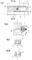
- Fig. 1
- einen Längsschnitt durch eine Vorrichtung mit zwei hintereinander angeordneten Verriegelungselementen,
- Fig. 2
- eine Draufsicht auf die Vorrichtung gemäß Fig. 1,
- Fig. 3
- einen Querschnitt gemäß Schnittlinie III-III in Fig. 3,
- Fig. 4
- eine Ansicht der Vorrichtung von unten in einem verriegelten Zustand,
- Fig. 5
- eine Ansicht der Vorrichtung von unten in einem entriegelten Zustand,
- Fig. 6
- einen Längsschnitt durch eine Vorrichtung mit einem Verriegelungselement,
- Fig. 7
- eine Draufsicht auf die Vorrichtung gemäß Fig. 6,
- Fig. 8
- einen Querschnitt gemäß Schnittlinie VIII-VIII in Fig. 7,
- Fig. 9
- eine Ansicht der Vorrichtung gemäß Fig. 6 von unten in einem verriegelten Zustand und
- Fig. 10
- eine Ansicht von unten in einem entriegelten Zustand.
- Fig. 1
- 2 shows a longitudinal section through a device with two locking elements arranged one behind the other,
- Fig. 2
- 2 shows a plan view of the device according to FIG. 1,
- Fig. 3
- 3 shows a cross section according to section line III-III in FIG. 3,
- Fig. 4
- a view of the device from below in a locked state,
- Fig. 5
- a view of the device from below in an unlocked state,
- Fig. 6
- 2 shows a longitudinal section through a device with a locking element,
- Fig. 7
- 6 shows a plan view of the device according to FIG. 6,
- Fig. 8
- 7 shows a cross section along section line VIII-VIII in FIG. 7,
- Fig. 9
- 6 from below in a locked state and
- Fig. 10
- a bottom view in an unlocked state.
Die Vorrichtung zur Verrieglung von Komponenten (1) besteht entsprechend der Ausführungsform in Fig. 1 aus zwei Verriegelungselementen (2), die im Bereich eines Trägers (3) drehbeweglich geführt sind. Bei dieser Ausführungsform ist der Träger (3) als ein Winkelprofil ausgebildet. Es ist aber auch möglich, als Träger (3) ein Bodenelement der Komponente (1) zu verwenden, oder eine separate Basisplatte (21) vorzusehen. Das Verriegelungselement (2) besteht im wesentlichen aus einem Bolzen (4), der im Bereich seines der Komponente (1) abgewandten Endes mit einer Traverse (5) verbunden ist, die den Bolzen (4) im Bereich ihrer Enden mit Vorsprüngen (6,7) überkragt. Die Vorsprünge (6,7) hintergreifen obere Begrenzungsstege (8,9) von Sitzschienen (10), die im Bereich eines Flugzeugbodens (11) angeordnet sind. Im Bereich einer von den Begrenzungsstegen (8,9) aufgespannten Ebene sind die Sitzschienen (10) mit Aufnahmeerweiterungen (12) sowie Verbindungsnuten (13) versehen, die die Aufnahmeerweiterungen (12) ineinander überleiten. Quer zu einer Längsrichtung der Sitzschiene (10) weisen die im wesentlichen kreisförmig konturierten Aufnahmeerweiterungen (11) einen größeren Durchmesser als die Verbindungsnuten (13) auf.According to the embodiment in FIG. 1, the device for locking components (1) consists of two locking elements (2) which are rotatably guided in the area of a carrier (3). In this embodiment, the carrier (3) is designed as an angle profile. However, it is also possible to use a base element of component (1) as support (3) or to provide a separate base plate (21). The locking element (2) consists essentially of a bolt (4) which is connected in the region of its end facing away from the component (1) to a crossmember (5) which, in the region of its ends, the bolt (4) with projections (6, 7) overhanging. The projections (6, 7) engage behind upper boundary webs (8, 9) of seat rails (10) which are arranged in the region of an aircraft floor (11). In the area of a plane spanned by the boundary webs (8, 9), the seat rails (10) are provided with receptacle extensions (12) and connecting grooves (13) which transfer the receptacle extensions (12) into one another. Transversely to a longitudinal direction of the seat rail (10), the substantially circularly contoured receiving extensions (11) have a larger diameter than the connecting grooves (13).
Zur Ermöglichung einer Arretierung der Verriegelungselemente (2) ist der Bolzen (4) mit einem Außengewinde (14) versehen, in das eine Mutter (15) eingreift, die den Bolzen (4) nach einem Anziehen relativ zum Träger (3) verspannt. Zur Verhinderung eines Verdrehens des Bolzens (4) bei einem Anziehen der Mutter (15) ist im Bereich einer Oberseite des Bolzens (4) eine Kerbe (16) vorgesehen, in die ein Schraubendreher eingreifen kann.To enable the locking elements (2) to be locked, the bolt (4) is provided with an external thread (14) into which a nut (15) engages, which braces the bolt (4) relative to the carrier (3) after tightening. To prevent the bolt (4) from twisting when the nut (15) is tightened, a notch (16) is provided in the area of an upper side of the bolt (4) into which a screwdriver can engage.
Zur Ermöglichung einer Fixierung der Komponenten (1) in Längsrichtung der Sitzschienen (10) sowie quer zur Längsrichtung der Sitz schienen (10) (x-y-Koordinaten) sind Positionierelemente (17) vorgesehen, die sich im wesentlichen parallel zum Bolzen (4) erstrecken. Die Positionierelemente (17) weisen einen Abstand zueinander auf, der dem Abstand der Aufnahmeerweiterungen (12) entspricht. Zur Ermöglichung einer kompakten Anordnung der Positionierelemente (17) sowie der Verriegelungselemente (2) sind die Positionierelemente (17) mit Seitenaussparungen (18) versehen, in die die Verriegelungselemente (2) mit den Vorsprüngen (6,7) in einem entriegelten Zustand eingreifen. Zur definierten Positionierung der Verriegelungselemente (2) in einem entriegelten Zustand weisen die Seitenaussparungen (18) Anschlagflächen (19) auf.To enable the components (1) to be fixed in the longitudinal direction of the seat rails (10) and transversely to the longitudinal direction of the seat rails (10) (xy coordinates) positioning elements (17) are provided which extend essentially parallel to the bolt (4). The positioning elements (17) are at a distance from one another which corresponds to the distance of the receiving extensions (12). To enable a compact arrangement of the positioning elements (17) and the locking elements (2), the positioning elements (17) are provided with side recesses (18) into which the locking elements (2) engage with the projections (6, 7) in an unlocked state. The side recesses (18) have stop faces (19) for the defined positioning of the locking elements (2) in an unlocked state.
Bei der Ausführungsform gemäß den Fig. 6 bis 10 ist lediglich ein Verriegelungselement (2) vorgesehen, das zwischen zwei Positionierelementen (17) angeordnet ist. Zur Verhinderung einer Verdrehung der aus den Positionierelementen (17) ausgebildeten Baugruppe relativ zum Träger (3) sind Arretierstifte (20) vorgesehen, die den Träger (3) durchdringen. Zur Verringerung des Baugewichtes ist es möglich, die Positionierelemente (17) mit einer Querschnittfläche zu versehen, die nicht die vollständige Aufnahmeerweiterung (12) ausfüllt, sondern sich lediglich über etwas mehr als die Hälfte der Querschnittfläche der Aufnahmeerweiterung (12) erstreckt. Auch bei einer derartigen Dimensionierung der Positionierelemente (17) ist eine zuverlässige Fixierung innerhalb der Aufnahmeerweiterung (12) gewährleistet.In the embodiment according to FIGS. 6 to 10, only one locking element (2) is provided, which is arranged between two positioning elements (17). To prevent rotation of the assembly formed from the positioning elements (17) relative to the carrier (3), locking pins (20) are provided which penetrate the carrier (3). To reduce the overall weight, it is possible to provide the positioning elements (17) with a cross-sectional area that does not fill the complete receptacle extension (12), but only extends over a little more than half the cross-sectional area of the receptacle extension (12). Even with such dimensioning of the positioning elements (17), a reliable fixation within the receptacle extension (12) is guaranteed.
Zur Durchführung einer Montage der Komponenten (1) im Bereich der Sitzschiene (10) werden die Verriegelungselemente (2) in ihre Entriegelungspositionierung verdreht und mit den als x-y-Stops ausgebildeten Positionierelementen (17) in die beispielsweise im Zollraster angeordneten Aufnahmeerweiterungen (12) eingeführt. Anschließend erfolgt eine Verdrehung der Verriegelungselemente (2) derart, daß die Vorsprünge (6,7) die Begrenzungsstege (8,9) untergreifen. Hierdurch ist auch eine Verriegelung in z-Richtung durchgeführt. Nach einem Einsetzen der Positionierelemente (17) in die Aufnahmeerweiterungen (12) erfolgt somit kein Verschieben mehr, sondern lediglich eine Arretierung der Verriegelungselemente (2).To carry out assembly of the components (1) in the region of the seat rail (10), the locking elements (2) are rotated into their unlocking position and, with the positioning elements (17) designed as xy stops, into the receptacle extensions (12) arranged, for example, in an inch grid. introduced. The locking elements (2) are then rotated such that the projections (6, 7) engage under the limiting webs (8, 9). As a result, locking in the z direction is also carried out. After the positioning elements (17) have been inserted into the receptacle extensions (12), there is no longer any displacement, but only a locking of the locking elements (2).
Claims (10)
Applications Claiming Priority (2)
| Application Number | Priority Date | Filing Date | Title |
|---|---|---|---|
| DE4212694A DE4212694C2 (en) | 1992-04-16 | 1992-04-16 | Locking device |
| DE4212694 | 1992-04-16 |
Publications (2)
| Publication Number | Publication Date |
|---|---|
| EP0565973A1 true EP0565973A1 (en) | 1993-10-20 |
| EP0565973B1 EP0565973B1 (en) | 1995-12-27 |
Family
ID=6456915
Family Applications (1)
| Application Number | Title | Priority Date | Filing Date |
|---|---|---|---|
| EP93105542A Expired - Lifetime EP0565973B1 (en) | 1992-04-16 | 1993-04-03 | Anchor means |
Country Status (3)
| Country | Link |
|---|---|
| US (1) | US5302065A (en) |
| EP (1) | EP0565973B1 (en) |
| DE (2) | DE4212694C2 (en) |
Cited By (18)
| Publication number | Priority date | Publication date | Assignee | Title |
|---|---|---|---|---|
| US5871318A (en) * | 1997-11-12 | 1999-02-16 | Be Aerospace, Inc. | Quick-release track fastener |
| EP1334865A2 (en) * | 2002-02-08 | 2003-08-13 | Grupo Antolin-Ingenieria, S.A. | Veritcal and automatic alignment device for a vehicle seat |
| FR2864481A1 (en) * | 2003-12-26 | 2005-07-01 | Renault Sas | Seat mounting arrangement for motor vehicle, has base with seat locking unit and two longitudinal guiding units received by respective guide ways, where each unit has guiding block rotated around vertical axis between two positions |
| DE102012012686A1 (en) * | 2012-06-27 | 2014-01-02 | Eads Deutschland Gmbh | Seat arrangement with longitudinally displaceable seat rows |
| US10562414B2 (en) | 2018-05-04 | 2020-02-18 | Lear Corporation | Track assembly |
| US10855037B2 (en) | 2018-12-17 | 2020-12-01 | Lear Corporation | Support assembly with a support member and a track assembly |
| US10882420B2 (en) | 2019-03-08 | 2021-01-05 | Lear Corporation | Track assembly |
| US10906431B2 (en) | 2018-05-04 | 2021-02-02 | Lear Corporation | Track assembly |
| US10926667B2 (en) | 2018-05-04 | 2021-02-23 | Lear Corporation | Track assembly |
| US10950977B2 (en) | 2018-12-18 | 2021-03-16 | Lear Corporation | Track assembly for a vehicle component |
| US11040638B2 (en) | 2018-05-04 | 2021-06-22 | Lear Corporation | Track assembly |
| US11040639B2 (en) | 2018-05-04 | 2021-06-22 | Lear Corporation | Track assembly |
| US11040653B2 (en) | 2019-02-25 | 2021-06-22 | Lear Corporation | Track assembly |
| US11117538B2 (en) | 2018-12-17 | 2021-09-14 | Lear Corporation | Electrical assembly |
| US11225201B2 (en) | 2018-12-10 | 2022-01-18 | Lear Corporation | Track assembly |
| US11299075B2 (en) | 2019-03-06 | 2022-04-12 | Lear Corporation | Electrical assembly |
| US11358497B2 (en) | 2018-05-04 | 2022-06-14 | Lear Corporation | Track system having a rolling member |
| US11440482B2 (en) | 2018-12-10 | 2022-09-13 | Lear Corporation | Track assembly |
Families Citing this family (28)
| Publication number | Priority date | Publication date | Assignee | Title |
|---|---|---|---|---|
| DE19634791C1 (en) * | 1996-08-29 | 1997-12-04 | Daimler Benz Aerospace Airbus | X-locking component for airfreight containers in aircraft cargo bay |
| GB2330614B (en) * | 1997-07-25 | 2001-10-03 | Baker Martin Aircraft Co | Fittings for securing seating and other equipment in aircraft |
| US5823727A (en) * | 1998-04-02 | 1998-10-20 | Lee; Ray | Anchor fittings for securing objects on a elongated track |
| DE19961734C1 (en) | 1999-12-21 | 2001-03-01 | Eads Airbus Gmbh | Freight storage system for aircraft has pneumatically-operated roller drive units and/or locking units for handled freight container or pallets |
| DE10034991C1 (en) * | 2000-07-19 | 2001-09-06 | Eads Airbus Gmbh | Tool to operate grooved nut on threaded shaft of mushroom-shaped fixing element has flat carrier with two carrier arms forming set-spanner-type aperture |
| DE10103840A1 (en) * | 2001-01-25 | 2002-08-01 | Junker & Partner Gmbh | Device for connecting two components |
| US20040237749A1 (en) * | 2003-05-29 | 2004-12-02 | Green Kevin J. | Extractable fastener |
| US7137768B2 (en) * | 2003-10-10 | 2006-11-21 | Illinois Tool Works Inc | Fastener assembly |
| US7021596B2 (en) * | 2004-02-11 | 2006-04-04 | Goodrich Corporation | Aircraft seat floor track quick release fitting |
| US7637705B2 (en) * | 2004-02-27 | 2009-12-29 | Valeda Company | Track fitting with visual indicia of engagement |
| US6918722B1 (en) | 2004-02-27 | 2005-07-19 | Valeda Company Llc | Double plunger track fitting |
| US7229238B2 (en) * | 2004-03-25 | 2007-06-12 | Valeda Company Llc | Wheelchair docking system |
| US7427049B2 (en) * | 2006-07-24 | 2008-09-23 | Ami Industries, Inc. | Aircraft seat floor track fitting |
| DE102006061455A1 (en) * | 2006-12-23 | 2008-06-26 | DRäGER AEROSPACE GMBH | Arrangement of at least one personal service unit in a vehicle |
| US9618118B2 (en) * | 2013-05-23 | 2017-04-11 | Alaska Airlines, Inc. | Air seal assembly for aircraft flap seal |
| EP3009350A1 (en) * | 2014-10-17 | 2016-04-20 | Airbus Defence and Space GmbH | Seat-mounting systems, seat or group of seats, aircraft cabin and method for attaching a seat or a group of seats |
| DE102017131057A1 (en) | 2017-12-22 | 2019-06-27 | Airbus Operations Gmbh | Seating group for a passenger plane |
| DE102018101836B4 (en) * | 2018-01-26 | 2023-05-04 | Airbus Operations Gmbh | Fastening system for fastening components in a vehicle |
| US10900607B1 (en) | 2018-03-14 | 2021-01-26 | Luther CIFERS | Accessory mounting track with one or more discrete locking positions |
| CN109334994B (en) * | 2018-11-19 | 2023-09-01 | 山东太古飞机工程有限公司 | Locking mechanism for airplane seat sliding rail |
| EP4253225A3 (en) * | 2018-12-31 | 2023-11-29 | Airbus Operations GmbH | Cargo hold loading and storage devices, systems, and associated methods |
| US11807142B2 (en) | 2019-03-06 | 2023-11-07 | Lear Corporation | Electrical track assembly |
| US11634101B2 (en) | 2019-10-04 | 2023-04-25 | Lear Corporation | Removable component system |
| US11463083B2 (en) | 2019-10-04 | 2022-10-04 | Lear Corporation | Electrical system |
| US11323114B2 (en) | 2019-10-04 | 2022-05-03 | Lear Corporation | Electrical system |
| US20210262173A1 (en) | 2020-02-21 | 2021-08-26 | Lear Corporation | Track system with a support member |
| US11505141B2 (en) | 2020-10-23 | 2022-11-22 | Lear Corporation | Electrical system with track assembly and support assembly |
| CN113955074B (en) * | 2021-12-03 | 2023-07-21 | 陕西飞机工业有限责任公司 | Quick-release lock for installing equipment in cabin |
Citations (5)
| Publication number | Priority date | Publication date | Assignee | Title |
|---|---|---|---|---|
| US3212457A (en) * | 1961-07-18 | 1965-10-19 | Brown Line Corp | Anchor means |
| US3241501A (en) * | 1964-01-08 | 1966-03-22 | Aid Corp | Hold-down device |
| US3306234A (en) * | 1964-05-14 | 1967-02-28 | Boeing Co | Securing device |
| US4230432A (en) * | 1979-02-27 | 1980-10-28 | Fairchild Industries, Inc. | Track fastener |
| US4449875A (en) * | 1982-07-22 | 1984-05-22 | Uop Inc. | Seat back mounting system |
Family Cites Families (9)
| Publication number | Priority date | Publication date | Assignee | Title |
|---|---|---|---|---|
| US1933536A (en) * | 1930-05-16 | 1933-11-07 | Floor Accessories Company Inc | Concrete insert |
| US1985333A (en) * | 1931-12-11 | 1934-12-25 | William R Wiley | Bolt |
| US2163446A (en) * | 1937-08-17 | 1939-06-20 | Richard P Heckman | Insert anchor |
| US2859057A (en) * | 1956-08-20 | 1958-11-04 | Aeroquip Corp | Rail |
| US3810534A (en) * | 1970-04-22 | 1974-05-14 | Ancra Corp | Automatic pallet locking device |
| DE2556000C2 (en) * | 1975-12-12 | 1983-02-03 | Vereinigte Flugtechnische Werke Gmbh, 2800 Bremen | Captive fastening element for seat rails |
| DE2649149B2 (en) * | 1976-10-28 | 1981-05-14 | Gardinia Vorhangschienenfabrik Klein & Wälder, 7972 Isny | End stop for releasable locking of curtain gliders |
| US4784554A (en) * | 1985-09-26 | 1988-11-15 | Break Douglas G | T-bolt assembly |
| EP0431786A1 (en) * | 1989-12-04 | 1991-06-12 | Camloc (U.K.) Limited | Quick release structural fastener |
-
1992
- 1992-04-16 DE DE4212694A patent/DE4212694C2/en not_active Expired - Lifetime
-
1993
- 1993-04-03 DE DE59301231T patent/DE59301231D1/en not_active Expired - Lifetime
- 1993-04-03 EP EP93105542A patent/EP0565973B1/en not_active Expired - Lifetime
- 1993-04-16 US US08/048,826 patent/US5302065A/en not_active Expired - Lifetime
Patent Citations (5)
| Publication number | Priority date | Publication date | Assignee | Title |
|---|---|---|---|---|
| US3212457A (en) * | 1961-07-18 | 1965-10-19 | Brown Line Corp | Anchor means |
| US3241501A (en) * | 1964-01-08 | 1966-03-22 | Aid Corp | Hold-down device |
| US3306234A (en) * | 1964-05-14 | 1967-02-28 | Boeing Co | Securing device |
| US4230432A (en) * | 1979-02-27 | 1980-10-28 | Fairchild Industries, Inc. | Track fastener |
| US4449875A (en) * | 1982-07-22 | 1984-05-22 | Uop Inc. | Seat back mounting system |
Cited By (28)
| Publication number | Priority date | Publication date | Assignee | Title |
|---|---|---|---|---|
| US5871318A (en) * | 1997-11-12 | 1999-02-16 | Be Aerospace, Inc. | Quick-release track fastener |
| EP1334865A2 (en) * | 2002-02-08 | 2003-08-13 | Grupo Antolin-Ingenieria, S.A. | Veritcal and automatic alignment device for a vehicle seat |
| FR2835790A1 (en) * | 2002-02-08 | 2003-08-15 | Antolin Grupo Ing Sa | DEVICE FOR VERTICAL AND AUTOMATIC SETTING OF A VEHICLE SEAT |
| US6736458B2 (en) | 2002-02-08 | 2004-05-18 | Grupo Antolin-Ingenieria, S.A. | Device for the vertical and automatic wedging of a vehicle seat |
| EP1334865A3 (en) * | 2002-02-08 | 2004-06-09 | Grupo Antolin-Ingenieria, S.A. | Veritcal and automatic alignment device for a vehicle seat |
| FR2864481A1 (en) * | 2003-12-26 | 2005-07-01 | Renault Sas | Seat mounting arrangement for motor vehicle, has base with seat locking unit and two longitudinal guiding units received by respective guide ways, where each unit has guiding block rotated around vertical axis between two positions |
| WO2005068247A2 (en) * | 2003-12-26 | 2005-07-28 | Renault S.A.S. | Fixture for mounting a seat on a car floor by means of retractable guiding blocks |
| WO2005068247A3 (en) * | 2003-12-26 | 2005-09-15 | Renault Sa | Fixture for mounting a seat on a car floor by means of retractable guiding blocks |
| DE102012012686A1 (en) * | 2012-06-27 | 2014-01-02 | Eads Deutschland Gmbh | Seat arrangement with longitudinally displaceable seat rows |
| DE102012012686B4 (en) * | 2012-06-27 | 2014-12-11 | Airbus Defence and Space GmbH | Aircraft with a number of rows of seat assemblies arranged longitudinally behind one another in the vehicle longitudinal direction with longitudinally displaceable seat rows, seat arrangement and their use |
| US10850644B2 (en) | 2018-05-04 | 2020-12-01 | Lear Corporation | Support assembly with cam assembly |
| US10906431B2 (en) | 2018-05-04 | 2021-02-02 | Lear Corporation | Track assembly |
| US10850645B2 (en) | 2018-05-04 | 2020-12-01 | Lear Corporation | Track assembly |
| US11358497B2 (en) | 2018-05-04 | 2022-06-14 | Lear Corporation | Track system having a rolling member |
| US10562414B2 (en) | 2018-05-04 | 2020-02-18 | Lear Corporation | Track assembly |
| US11040639B2 (en) | 2018-05-04 | 2021-06-22 | Lear Corporation | Track assembly |
| US10889208B2 (en) | 2018-05-04 | 2021-01-12 | Lear Corporation | Track assembly |
| US11040638B2 (en) | 2018-05-04 | 2021-06-22 | Lear Corporation | Track assembly |
| US10926667B2 (en) | 2018-05-04 | 2021-02-23 | Lear Corporation | Track assembly |
| US10759308B2 (en) | 2018-05-04 | 2020-09-01 | Lear Corporation | Support assembly |
| US11225201B2 (en) | 2018-12-10 | 2022-01-18 | Lear Corporation | Track assembly |
| US11440482B2 (en) | 2018-12-10 | 2022-09-13 | Lear Corporation | Track assembly |
| US10855037B2 (en) | 2018-12-17 | 2020-12-01 | Lear Corporation | Support assembly with a support member and a track assembly |
| US11117538B2 (en) | 2018-12-17 | 2021-09-14 | Lear Corporation | Electrical assembly |
| US10950977B2 (en) | 2018-12-18 | 2021-03-16 | Lear Corporation | Track assembly for a vehicle component |
| US11040653B2 (en) | 2019-02-25 | 2021-06-22 | Lear Corporation | Track assembly |
| US11299075B2 (en) | 2019-03-06 | 2022-04-12 | Lear Corporation | Electrical assembly |
| US10882420B2 (en) | 2019-03-08 | 2021-01-05 | Lear Corporation | Track assembly |
Also Published As
| Publication number | Publication date |
|---|---|
| EP0565973B1 (en) | 1995-12-27 |
| DE4212694C2 (en) | 1995-09-21 |
| DE59301231D1 (en) | 1996-02-08 |
| DE4212694A1 (en) | 1993-10-21 |
| US5302065A (en) | 1994-04-12 |
Similar Documents
| Publication | Publication Date | Title |
|---|---|---|
| EP0565973B1 (en) | Anchor means | |
| DE602005005869T2 (en) | Quick release for attaching a flange to a rail | |
| DE3726711C2 (en) | ||
| EP0583295A1 (en) | Quick-release fastening device. | |
| DE3222202A1 (en) | LOCKING ELEMENT FOR LOCKING IN THE AIR COMPARTMENT | |
| EP0251991A1 (en) | Method of coupling at least two ISO container bodies to constitute a transport unit, as well as the transport unit | |
| DE19538988A1 (en) | Table bridging device | |
| DE19900267A1 (en) | Device for attaching a first part to a fixed second part | |
| DE4404392C2 (en) | Twist lock for releasably connecting corner fittings of containers standing on top of each other | |
| DE10124618B4 (en) | Lock fitting for a vehicle seat | |
| DE3831807A1 (en) | HOLDING DEVICE | |
| DE2747064A1 (en) | Interlocking formwork element frame - comprises profile bar with groove containing slots for turning lock heads | |
| DE4102273C2 (en) | Connecting element | |
| DE20221792U1 (en) | Arrangement for securing cargo | |
| DE3447178A1 (en) | Aircraft passenger seat | |
| EP0554658B1 (en) | Device for alignment and locking palettes inside an aircraft | |
| WO1983004231A1 (en) | Device for trimming a container | |
| DE2818292A1 (en) | CONNECTING DEVICE FOR SWIMMING BOATS | |
| DE3711523A1 (en) | OVERALL POINT CLAMPING DEVICE | |
| EP0323623B1 (en) | Method of comporting at least two layers, each consisting of an odd number of bodies, to constitute a transport unit, as well as the transport unit | |
| DE102018101836B4 (en) | Fastening system for fastening components in a vehicle | |
| DE2260436A1 (en) | DEVICE FOR LOCKING CONTAINERS ON VEHICLES | |
| DE4423971C2 (en) | Locking device for vehicle seats, in particular motor vehicle seats | |
| EP0603559B1 (en) | Removable trailer coupling | |
| EP1036944A2 (en) | Fastening device and coupler housing equipped with such a device |
Legal Events
| Date | Code | Title | Description |
|---|---|---|---|
| PUAI | Public reference made under article 153(3) epc to a published international application that has entered the european phase |
Free format text: ORIGINAL CODE: 0009012 |
|
| AK | Designated contracting states |
Kind code of ref document: A1 Designated state(s): DE FR GB IT NL |
|
| 17P | Request for examination filed |
Effective date: 19940203 |
|
| 17Q | First examination report despatched |
Effective date: 19941219 |
|
| RAP1 | Party data changed (applicant data changed or rights of an application transferred) |
Owner name: DAIMLER-BENZ AEROSPACE AIRBUS GESELLSCHAFT MIT BES |
|
| GRAA | (expected) grant |
Free format text: ORIGINAL CODE: 0009210 |
|
| AK | Designated contracting states |
Kind code of ref document: B1 Designated state(s): DE FR GB IT NL |
|
| REF | Corresponds to: |
Ref document number: 59301231 Country of ref document: DE Date of ref document: 19960208 |
|
| ITF | It: translation for a ep patent filed |
Owner name: INVENTION S.N.C. |
|
| GBT | Gb: translation of ep patent filed (gb section 77(6)(a)/1977) |
Effective date: 19960217 |
|
| ET | Fr: translation filed | ||
| PLBE | No opposition filed within time limit |
Free format text: ORIGINAL CODE: 0009261 |
|
| STAA | Information on the status of an ep patent application or granted ep patent |
Free format text: STATUS: NO OPPOSITION FILED WITHIN TIME LIMIT |
|
| 26N | No opposition filed | ||
| REG | Reference to a national code |
Ref country code: FR Ref legal event code: CD |
|
| REG | Reference to a national code |
Ref country code: GB Ref legal event code: IF02 |
|
| PGFP | Annual fee paid to national office [announced via postgrant information from national office to epo] |
Ref country code: FR Payment date: 20110510 Year of fee payment: 19 Ref country code: DE Payment date: 20110421 Year of fee payment: 19 |
|
| PGFP | Annual fee paid to national office [announced via postgrant information from national office to epo] |
Ref country code: NL Payment date: 20110426 Year of fee payment: 19 Ref country code: GB Payment date: 20110421 Year of fee payment: 19 |
|
| PGFP | Annual fee paid to national office [announced via postgrant information from national office to epo] |
Ref country code: IT Payment date: 20110422 Year of fee payment: 19 |
|
| REG | Reference to a national code |
Ref country code: NL Ref legal event code: V1 Effective date: 20121101 |
|
| GBPC | Gb: european patent ceased through non-payment of renewal fee |
Effective date: 20120403 |
|
| REG | Reference to a national code |
Ref country code: FR Ref legal event code: ST Effective date: 20121228 |
|
| PG25 | Lapsed in a contracting state [announced via postgrant information from national office to epo] |
Ref country code: GB Free format text: LAPSE BECAUSE OF NON-PAYMENT OF DUE FEES Effective date: 20120403 |
|
| REG | Reference to a national code |
Ref country code: DE Ref legal event code: R119 Ref document number: 59301231 Country of ref document: DE Effective date: 20121101 |
|
| PG25 | Lapsed in a contracting state [announced via postgrant information from national office to epo] |
Ref country code: FR Free format text: LAPSE BECAUSE OF NON-PAYMENT OF DUE FEES Effective date: 20120430 Ref country code: IT Free format text: LAPSE BECAUSE OF NON-PAYMENT OF DUE FEES Effective date: 20120403 |
|
| PG25 | Lapsed in a contracting state [announced via postgrant information from national office to epo] |
Ref country code: NL Free format text: LAPSE BECAUSE OF NON-PAYMENT OF DUE FEES Effective date: 20121101 |
|
| PG25 | Lapsed in a contracting state [announced via postgrant information from national office to epo] |
Ref country code: DE Free format text: LAPSE BECAUSE OF NON-PAYMENT OF DUE FEES Effective date: 20121101 |