EP0565905A1 - Control and shut-off valve - Google Patents
Control and shut-off valve Download PDFInfo
- Publication number
- EP0565905A1 EP0565905A1 EP93104601A EP93104601A EP0565905A1 EP 0565905 A1 EP0565905 A1 EP 0565905A1 EP 93104601 A EP93104601 A EP 93104601A EP 93104601 A EP93104601 A EP 93104601A EP 0565905 A1 EP0565905 A1 EP 0565905A1
- Authority
- EP
- European Patent Office
- Prior art keywords
- valve
- disc
- shut
- passage opening
- control
- Prior art date
- Legal status (The legal status is an assumption and is not a legal conclusion. Google has not performed a legal analysis and makes no representation as to the accuracy of the status listed.)
- Granted
Links
Images

Classifications
-
- F—MECHANICAL ENGINEERING; LIGHTING; HEATING; WEAPONS; BLASTING
- F16—ENGINEERING ELEMENTS AND UNITS; GENERAL MEASURES FOR PRODUCING AND MAINTAINING EFFECTIVE FUNCTIONING OF MACHINES OR INSTALLATIONS; THERMAL INSULATION IN GENERAL
- F16K—VALVES; TAPS; COCKS; ACTUATING-FLOATS; DEVICES FOR VENTING OR AERATING
- F16K11/00—Multiple-way valves, e.g. mixing valves; Pipe fittings incorporating such valves
- F16K11/02—Multiple-way valves, e.g. mixing valves; Pipe fittings incorporating such valves with all movable sealing faces moving as one unit
- F16K11/06—Multiple-way valves, e.g. mixing valves; Pipe fittings incorporating such valves with all movable sealing faces moving as one unit comprising only sliding valves, i.e. sliding closure elements
- F16K11/072—Multiple-way valves, e.g. mixing valves; Pipe fittings incorporating such valves with all movable sealing faces moving as one unit comprising only sliding valves, i.e. sliding closure elements with pivoted closure members
- F16K11/074—Multiple-way valves, e.g. mixing valves; Pipe fittings incorporating such valves with all movable sealing faces moving as one unit comprising only sliding valves, i.e. sliding closure elements with pivoted closure members with flat sealing faces
- F16K11/0746—Multiple-way valves, e.g. mixing valves; Pipe fittings incorporating such valves with all movable sealing faces moving as one unit comprising only sliding valves, i.e. sliding closure elements with pivoted closure members with flat sealing faces with two or more closure plates comprising a single lever control
-
- F—MECHANICAL ENGINEERING; LIGHTING; HEATING; WEAPONS; BLASTING
- F16—ENGINEERING ELEMENTS AND UNITS; GENERAL MEASURES FOR PRODUCING AND MAINTAINING EFFECTIVE FUNCTIONING OF MACHINES OR INSTALLATIONS; THERMAL INSULATION IN GENERAL
- F16K—VALVES; TAPS; COCKS; ACTUATING-FLOATS; DEVICES FOR VENTING OR AERATING
- F16K3/00—Gate valves or sliding valves, i.e. cut-off apparatus with closing members having a sliding movement along the seat for opening and closing
- F16K3/02—Gate valves or sliding valves, i.e. cut-off apparatus with closing members having a sliding movement along the seat for opening and closing with flat sealing faces; Packings therefor
- F16K3/04—Gate valves or sliding valves, i.e. cut-off apparatus with closing members having a sliding movement along the seat for opening and closing with flat sealing faces; Packings therefor with pivoted closure members
- F16K3/06—Gate valves or sliding valves, i.e. cut-off apparatus with closing members having a sliding movement along the seat for opening and closing with flat sealing faces; Packings therefor with pivoted closure members in the form of closure plates arranged between supply and discharge passages
- F16K3/08—Gate valves or sliding valves, i.e. cut-off apparatus with closing members having a sliding movement along the seat for opening and closing with flat sealing faces; Packings therefor with pivoted closure members in the form of closure plates arranged between supply and discharge passages with circular plates rotatable around their centres
-
- F—MECHANICAL ENGINEERING; LIGHTING; HEATING; WEAPONS; BLASTING
- F16—ENGINEERING ELEMENTS AND UNITS; GENERAL MEASURES FOR PRODUCING AND MAINTAINING EFFECTIVE FUNCTIONING OF MACHINES OR INSTALLATIONS; THERMAL INSULATION IN GENERAL
- F16K—VALVES; TAPS; COCKS; ACTUATING-FLOATS; DEVICES FOR VENTING OR AERATING
- F16K3/00—Gate valves or sliding valves, i.e. cut-off apparatus with closing members having a sliding movement along the seat for opening and closing
- F16K3/02—Gate valves or sliding valves, i.e. cut-off apparatus with closing members having a sliding movement along the seat for opening and closing with flat sealing faces; Packings therefor
- F16K3/04—Gate valves or sliding valves, i.e. cut-off apparatus with closing members having a sliding movement along the seat for opening and closing with flat sealing faces; Packings therefor with pivoted closure members
- F16K3/10—Gate valves or sliding valves, i.e. cut-off apparatus with closing members having a sliding movement along the seat for opening and closing with flat sealing faces; Packings therefor with pivoted closure members with special arrangements for separating the sealing faces or for pressing them together
-
- Y—GENERAL TAGGING OF NEW TECHNOLOGICAL DEVELOPMENTS; GENERAL TAGGING OF CROSS-SECTIONAL TECHNOLOGIES SPANNING OVER SEVERAL SECTIONS OF THE IPC; TECHNICAL SUBJECTS COVERED BY FORMER USPC CROSS-REFERENCE ART COLLECTIONS [XRACs] AND DIGESTS
- Y10—TECHNICAL SUBJECTS COVERED BY FORMER USPC
- Y10T—TECHNICAL SUBJECTS COVERED BY FORMER US CLASSIFICATION
- Y10T137/00—Fluid handling
- Y10T137/4238—With cleaner, lubrication added to fluid or liquid sealing at valve interface
-
- Y—GENERAL TAGGING OF NEW TECHNOLOGICAL DEVELOPMENTS; GENERAL TAGGING OF CROSS-SECTIONAL TECHNOLOGIES SPANNING OVER SEVERAL SECTIONS OF THE IPC; TECHNICAL SUBJECTS COVERED BY FORMER USPC CROSS-REFERENCE ART COLLECTIONS [XRACs] AND DIGESTS
- Y10—TECHNICAL SUBJECTS COVERED BY FORMER USPC
- Y10T—TECHNICAL SUBJECTS COVERED BY FORMER US CLASSIFICATION
- Y10T137/00—Fluid handling
- Y10T137/7504—Removable valve head and seat unit
- Y10T137/7613—Threaded into valve casing
-
- Y—GENERAL TAGGING OF NEW TECHNOLOGICAL DEVELOPMENTS; GENERAL TAGGING OF CROSS-SECTIONAL TECHNOLOGIES SPANNING OVER SEVERAL SECTIONS OF THE IPC; TECHNICAL SUBJECTS COVERED BY FORMER USPC CROSS-REFERENCE ART COLLECTIONS [XRACs] AND DIGESTS
- Y10—TECHNICAL SUBJECTS COVERED BY FORMER USPC
- Y10T—TECHNICAL SUBJECTS COVERED BY FORMER US CLASSIFICATION
- Y10T137/00—Fluid handling
- Y10T137/8593—Systems
- Y10T137/86493—Multi-way valve unit
- Y10T137/86718—Dividing into parallel flow paths with recombining
- Y10T137/86743—Rotary
Definitions
- the invention relates to a control and shut-off valve, in particular for water fittings, with a valve seat disk made of ceramic material and non-rotatably held in the housing and having at least one passage opening, and a ground seat surface on which a valve regulating disk, which is also made of ceramic material and rotatable coaxially to the central axis, also has abuts a ground sealing surface, with both disks having a circumferential, circular disk edge on the outer region of the passage openings.
- a valve of this type is known from the document DE 31 40 353 C2.
- the increased abrasion wear in the ring area of the discs lies in the fact that the finely machined sealing surfaces in this area are not wetted by the water passing through the valve and consequently run dry during the period of use.
- grains or grain aggregates of the ceramic surface that have been removed from the finely machined sealing surface are not washed out of the circumferential ring area, but are ground between the permanently contacting sealing and sliding surfaces.
- the valve regulating disk is thus designed as a "half disk". It was found through investigations that the valve regulating disc is tilted to the valve seat disc, at least in the micro range, which leads to severe abrasion wear on the edges of the valve regulating disc designed as a "half disc” and the sealing surface of the valve seat disc, so that this occurs after relatively short opening and closing processes (Load change numbers) between 20,000 and 50,000 can lead to leaks, which is extremely undesirable.
- the invention has for its object to improve the valve specified in the preamble of claim 1 and to design so that the disadvantages mentioned are avoided and the smoothness of the valve is maintained over a relatively long period of use.
- the disk edge which does not act as a sealing surface in the closed position, has one or more recessed surface parts in the area of the ground sealing surface of the regulating disk and / or the valve seat disk from the sealing plane.
- the circumferential ring area of the sealing surface is interrupted and is wetted here with the water flowing through the valve disks, which also acts as a lubricant.
- grains or grain aggregates loosened from the sealing surface can be washed out of the sealing area.
- the remaining sealing surfaces in the area of the circular ring ensure that tilting of the two disks to one another is also avoided in the micro area and thus a long tightness of the valve disk pairing is ensured.
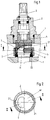
- valves 1 to 4 installed in a fitting 1 for water pipes shown in part.
- the valve members are arranged in a housing 2, which is screwed into the fitting 1 by means of a thread, a coaxial inlet opening 11 being formed in the housing 2, which is connected tightly to a water inlet channel of the fitting 1 by means of a seal 22.
- a valve spindle 3 is rotatably mounted axially fixed with a rotary member 4.
- a valve regulating disc 5 made of ceramic material rotatably.
- a valve seat disk 6 Upstream of the valve regulating disk 5, a valve seat disk 6 is arranged in a rotationally fixed manner in longitudinal grooves 21 of the housing 2.
- the valve seat disc 6 lies with a ground sealing surface 61 on a likewise ground sealing surface 51 of the valve regulating disc 5. The surfaces are finished so that a watertight barrier is possible.
- An approximately semicircular passage opening 7 is provided in each half of the valve regulating disk 5 and the valve seat disk 6.
- the control and shut-off valve In the position of the two valve disks shown in FIG. 1, the control and shut-off valve is in the fully open position.
- the fresh water entering the inlet opening 11 passes through the two through openings 7 and then exits radially at outlet openings 12 formed in the side wall of the housing 2 and then reaches the outflow channel of the fitting 1.
- the valve regulating disk 5 becomes the valve seat disk accordingly 6 rotated so that the two valve disks 5,6 shut off the flow when rotated by 180 o .
- a correspondingly restricted passage is made possible
- axially recessed surface parts 8 are formed on the valve seat disk 5 in the area of the outer ring arc in half of the passage opening 7 in an angular area 82, as can be seen in particular from FIG. 4.
- the surface parts 8 are set back by a distance 81 of approximately 0.2 to 0.4 mm. This recessed surface parts 8 ensures that the outer circumferential ring surface is interrupted.
- the set back parts 8 form fine radial slots when in contact with the valve seat disc 6, through which the water present in the valve can pass and thus abrasion particles can be washed out in the area of the sealing surfaces 51, 61.
- the friction behavior is favorably influenced by the presence of the water.
- FIG. 1 Another exemplary embodiment of the valve regulating disk 5 is shown in FIG.
- the recessed surface parts 8 encompass almost the entire annular arc in the outer region of the passage opening 7. Only an arc piece 52 with a length of approximately 1.5 to 2 mm perpendicular to the base surface of the semicircular cross section of the passage opening 7 is located in the plane of the sealing surface 51 and causes the support.
- valve regulating disk 5 is shown in FIG. Instead of an arc piece, which is arranged approximately perpendicular to the base of the semicircular cross section of the passage opening 7, here three approximately symmetrically arranged support surfaces are provided in the plane of the sealing surface 51 and in each case recessed surface parts 8 are arranged between them.
- valve seat disk 6 is shown in FIG.
- Sealing surface 61 are in this case arranged in the half opposite the passage opening 7 in the outer edge area recessed surface parts 8.
- the surface parts 8 extend radially towards the center point to such an extent that in the closed position the valve regulating disk 5 is securely sealed with the passage opening 7 on the valve seat disk 6.
- the water present in the housing 2 can thus penetrate into this area of the recessed surface parts 8 and cause wetting of the two sealing surfaces 51, 61 in the ring area.
- the valve regulating disk 5 need not have any recessed surface parts 8.
- the valve seat disk according to FIG. 7 can also cooperate with one of the valve regulating disks 5 shown in FIGS. 4 to 6, in which case the remaining part of the sealing surface 51/52 in the ring area of the valve regulating disk 5 must be designed such that it does not enter the recessed surface parts 8 of the valve seat plate 6 can dip.
Landscapes
- General Engineering & Computer Science (AREA)
- Engineering & Computer Science (AREA)
- Mechanical Engineering (AREA)
- Sliding Valves (AREA)
- Magnetic Resonance Imaging Apparatus (AREA)
- Detergent Compositions (AREA)
- Lift Valve (AREA)
- Curing Cements, Concrete, And Artificial Stone (AREA)
- Control Of Combustion (AREA)
- Vehicle Cleaning, Maintenance, Repair, Refitting, And Outriggers (AREA)
- Vehicle Body Suspensions (AREA)
- Multiple-Way Valves (AREA)
- Domestic Plumbing Installations (AREA)
Abstract
Description
Die Erfindung betrifft ein Regel- und Absperrventil, insbesondere für Wasserarmaturen, mit einer im Gehäuse unverdrehbar gehaltenen, wenigstens eine Durchtrittsöffnung aufweisenden Ventilsitzscheibe aus Keramikmaterial und geschliffener Sitzoberfläche, an der eine koaxial zur Mittelachse drehbare, ebenfalls aus Keramikmaterial hergestellte, wenigstens eine Durchtrittsöffnung aufweisende Ventilregulierscheibe mit einer geschliffenen Dichtfläche anliegt, wobei beide Scheiben am Außenbereich der Durchtrittsöffnungen einen umlaufenden, kreisringförmigen Scheibenrand haben.
Ein Ventil dieser Gattung ist aus der Druckschrift DE 31 40 353 C2 bekannt. Bei diesem Ventil ist in den beiden Ventilscheiben jeweils in der einen Hälfte der Scheiben eine etwa halbkreisförmige Durchtrittsöffnung vorgesehen, so daß die bewegliche Scheibe durch eine Verdrehung um 180o von der vollgeschlossenen Stellung in die vollgeöffnete Stellung bewegbar ist. Durch das im Außenbereich der Durchtrittsöffnungen vorgesehene Ringstück werden die beiden etwa kreisförmigen Scheiben sicher aufeinander geführt. Hierbei kann es jedoch in dem Ringbereich zu ungünstigen Veränderungen des Reibkoeffizienten der Keramikpaarung aufgrund von Abrasionsverschleiß kommen, wie es auch bei Untersuchungen im Dauertest festgestellt worden ist. Mit der Erhöhung des Reibkoeffizienten steigen gleichzeitig in unerwünschter Weise auch die Bedienkräfte im Laufe der Gebrauchszeit.
Der erhöhte Abrasionsverschleiß im Ringbereich der Scheiben liegt darin, daß die feinstbearbeiteten Dichtflächen in diesem Bereich nicht von dem durch das Ventil durchtretende Wasser benetzt werden und im Laufe der Benutzungszeit folglich trocken laufen. Hinzu kommt, daß aus der feinstbearbeiteten Dichtfläche herausgelöste Körner oder Kornverbände der Keramikoberfläche aus dem umlaufenden Ringbereich nicht herausgeschwemmt, sondern zwischen den dauernd in Kontakt stehenden Dicht- und Gleitflächen zermahlen werden.
Ferner ist es bereits bekannt (DE-OS 28 05 038 / DE-GM 78 27 429), bei Ventilen mit Keramikscheiben, welche über einen Drehwinkel von 180o von der Schließstellung in die Offenstellung bewegbar sind, die drehbare Ventilregulierscheibe mit einer Dichtfläche zu versehen, die als Kreissegmentfläche ausgebildet ist. Hierbei entfällt dann die Kreisringfläche am Außenrand der Ventilregulierscheibe. Die Ventilregulierscheibe ist also quasi als "Halbscheibe" ausgebildet. Hierbei wurde durch Untersuchungen festgestellt, daß die Ventilregulierscheibe zur Ventilsitzscheibe zumindest im Mikrobereich Verkippungen erfährt, was zu einem starken Abrasionsverschleiß an den Kanten der als "Halbscheibe" ausgebildeten Ventilregulierscheibe und der Dichtfläche der Ventilsitzscheibe führt, so daß dieses schon nach relativ kurzen Öffnungs- und Schließvorgängen (Lastwechselzahlen) zwischen 20.000 und 50.000 zu Undichtigkeiten führen kann, was äußerst unerwünscht ist.
Der Erfindung liegt die Aufgabe zugrunde, das im Oberbegriff des Anspruchs 1 angegebene Ventil zu verbessern und so auszubilden, daß die eingangs aufgeführten Nachteile vermieden werden und die Leichtgängigkeit des Ventils über einen relativ langen Benutzungszeitraum erhalten bleibt.The invention relates to a control and shut-off valve, in particular for water fittings, with a valve seat disk made of ceramic material and non-rotatably held in the housing and having at least one passage opening, and a ground seat surface on which a valve regulating disk, which is also made of ceramic material and rotatable coaxially to the central axis, also has abuts a ground sealing surface, with both disks having a circumferential, circular disk edge on the outer region of the passage openings.
A valve of this type is known from the document DE 31 40 353 C2. In this valve in the two valve disks an approximately semi-circular through opening is provided in each case in one half of the discs, so that the movable plate is movable by a rotation through 180 ° from the fully closed position to the fully open position. The two approximately circular disks are securely guided on one another by the ring piece provided in the outer region of the passage openings. However, it can be in In the ring area, there are unfavorable changes in the coefficient of friction of the ceramic pairing due to abrasion wear, as was also found in tests in the endurance test. With the increase in the coefficient of friction, the operating forces also undesirably increase in the course of the period of use.
The increased abrasion wear in the ring area of the discs lies in the fact that the finely machined sealing surfaces in this area are not wetted by the water passing through the valve and consequently run dry during the period of use. In addition, grains or grain aggregates of the ceramic surface that have been removed from the finely machined sealing surface are not washed out of the circumferential ring area, but are ground between the permanently contacting sealing and sliding surfaces.
Further, it is already known to provide (DE-OS 28 05 038 / DE-GM 78 27 429) for valves with ceramic disks, which are movable o from the closed position to the open position over a rotation angle of 180, the rotatable valve regulating disc with a sealing surface , which is designed as a circular segment surface. The circular ring surface on the outer edge of the valve regulating disc is then omitted. The valve regulating disk is thus designed as a "half disk". It was found through investigations that the valve regulating disc is tilted to the valve seat disc, at least in the micro range, which leads to severe abrasion wear on the edges of the valve regulating disc designed as a "half disc" and the sealing surface of the valve seat disc, so that this occurs after relatively short opening and closing processes (Load change numbers) between 20,000 and 50,000 can lead to leaks, which is extremely undesirable.
The invention has for its object to improve the valve specified in the preamble of claim 1 and to design so that the disadvantages mentioned are avoided and the smoothness of the valve is maintained over a relatively long period of use.
Diese Aufgabe wird erfindungsgemäß dadurch gelöst, daß der in der Schließstellung nicht als Dichtfläche wirkende Scheibenrand im Bereich der geschliffenen Dichtfläche der Regulierscheibe und/oder der Ventilsitzscheibe aus der Dichtebene ein oder mehrere zurückgesetzte Flächenteile aufweist. Mit diesen Maßnahmen wird erreicht, daß der umlaufende Ringbereich der Dichtfläche unterbrochen wird und hier mit dem durch die Ventilscheiben durchströmenden Wasser benetzt wird, welches auch als Gleitmittel wirkt. Außerdem können aus der Dichtfläche herausgelöste Körner oder Kornverbände aus dem Dichtbereich herausgeschwemmt werden. Andererseits wird durch die verbleibenden Dichtflächen im Bereich des Kreisrings sichergestellt, daß ein Verkippen der beiden Scheiben zueinander auch im Mikrobereich vermieden wird und somit eine lange Dichtheit der Ventilscheibenpaarung gewährleistet ist.
In den Ansprüchen 2 bis 7 sind Ausgestaltungen der Erfindung dargestellt.This object is achieved in that the disk edge, which does not act as a sealing surface in the closed position, has one or more recessed surface parts in the area of the ground sealing surface of the regulating disk and / or the valve seat disk from the sealing plane. With these measures it is achieved that the circumferential ring area of the sealing surface is interrupted and is wetted here with the water flowing through the valve disks, which also acts as a lubricant. In addition, grains or grain aggregates loosened from the sealing surface can be washed out of the sealing area. On the other hand, the remaining sealing surfaces in the area of the circular ring ensure that tilting of the two disks to one another is also avoided in the micro area and thus a long tightness of the valve disk pairing is ensured.
In the
Ausführungsbeispiele der Erfindung sind in der Zeichnung dargestellt und werden im folgenden näher erläutert. Es zeigt
- Figur 1
- ein Regel- und Absperrventil im Längsschnitt;
Figur 2- das Regel- und Absperrventil gemäß Figur 1 in der Schnittebene I;
Figur 3- die in Figur 1 gezeigte Mengenregulierventilscheibe in der Schnittebene III der
Figur 4; Figur 4- die in Figur 1 gezeigte Ventilregulierscheibe in Draufsicht auf die Dichtfläche;
Figur 5- eine andere Ventilregulierscheibe in Draufsicht auf die Dichtfläche;
Figur 6- eine weitere Ventilregulierscheibe in Draufsicht auf die Dichtfläche;
Figur 7- eine andere Ventilsitzscheibe in Draufsicht auf die Dichtfläche.
- Figure 1
- a control and shut-off valve in longitudinal section;
- Figure 2
- the control and shut-off valve according to Figure 1 in the sectional plane I;
- Figure 3
- the flow control valve disc shown in Figure 1 in the section plane III of Figure 4;
- Figure 4
- the valve regulating disc shown in Figure 1 in plan view of the sealing surface;
- Figure 5
- another valve regulating disc in plan view of the sealing surface;
- Figure 6
- another valve regulating disc in plan view of the sealing surface;
- Figure 7
- another valve seat disc in plan view of the sealing surface.
Der Einfachheit halber sind bei den Ausführungsbeispielen in der Zeichnung gleiche oder entsprechende Elemente mit jeweils gleichen Bezugszeichen versehen.
Das in den Figuren 1 bis 4 dargestellte Regel- und Absperrventil ist in einer zum Teil gezeigten Armatur 1 für Wasserleitungen einmontiert dargestellt. Hierbei sind die Ventilorgane in einem Gehäuse 2 angeordnet, welches mittels Gewinde in die Armatur 1 eingeschraubt ist, wobei in dem Gehäuse 2 eine koaxiale Einlaßöffnung 11 ausgebildet ist, die mit Hilfe einer Dichtung 22 dicht mit einem Wasserzulaufkanal der Armatur 1 verbunden ist. In dem Gehäuse 2 ist koaxial eine Ventilspindel 3 mit einem Drehglied 4 axial festliegend drehbar gelagert. Von dem Drehglied 4 ist eine Ventilregulierscheibe 5 aus Keramikmaterial drehfest aufgenommen.
Stromaufwärts vor der Ventilregulierscheibe 5 ist eine Ventilsitzscheibe 6 drehfest in Längsnuten 21 des Gehäuses 2 angeordnet. Die Ventilsitzscheibe 6 liegt mit einer geschliffenen Dichtfläche 61 an einer ebenfalls geschliffenen Dichtfläche 51 der Ventilregulierscheibe 5 an. Die Oberflächen sind so feinbearbeitet, daß eine wasserdichte Absperrung ermöglicht ist. In jeweils einer Hälfte der Ventilregulierscheibe 5 und der Ventilsitzscheibe 6 ist eine etwa halbkreisförmig ausgebildete Durchtrittsöffnung 7 vorgesehen.
In der in Figur 1 gezeigten Stellung der beiden Ventilscheiben befindet sich das Regel- und Absperrventil in voll geöffneter Stellung. Das an der Einlaßöffnung 11 eintretende Frischwasser gelangt durch die beiden Durchtrittsöffnungen 7 und tritt danach radial an in der Seitenwandung des Gehäuses 2 ausgebildeten Auslaßöffnungen 12 aus und gelangt dann in den Abströmkanal der Armatur 1. Durch Drehung der Ventilspindel 3 wird die Ventilregulierscheibe 5 entsprechend zur Ventilsitzscheibe 6 verdreht, so daß bei einer Drehung um 180o die beiden Ventilscheiben 5,6 den Durchfluß absperren. In Zwischenstellungen wird ein entsprechend gedrosselter Durchtritt ermöglicht.For the sake of simplicity, the same or corresponding elements are provided with the same reference numerals in the exemplary embodiments in the drawing.
The control and shut-off valve shown in Figures 1 to 4 is shown installed in a fitting 1 for water pipes shown in part. Here, the valve members are arranged in a
Upstream of the valve regulating
In the position of the two valve disks shown in FIG. 1, the control and shut-off valve is in the fully open position. The fresh water entering the inlet opening 11 passes through the two through
Zur Minderung des Abrasionsverschleißes im äußeren Ringbereich der beiden Ventilscheiben sind an der Ventilsitzscheibe 5 im Bereich des äußeren Ringbogens in der Hälfte der Durchtrittsöffnung 7 in einem Winkelbereich 82 axial zurückgesetzte Flächenteile 8 ausgebildet, wie es insbesondere aus Figur 4 zu entnehmen ist.
Die Flächenteile 8 sind um eine Strecke 81 von etwa 0,2 bis 0,4 mm zurückgesetzt. Durch diese zurückgesetzten Flächenteile 8 wird erreicht, daß die äußere umlaufende Ringfläche unterbrochen wird. Die zurückgesetzten Flächenteile 8 bilden bei Anlage an der Ventilsitzscheibe 6 feine Radialschlitze, durch die das im Ventil vorhandene Wasser hindurchtreten kann und somit Abriebpartikel im Bereich der Dichtflächen 51,61 herausgeschwemmt werden können. Andererseits wird durch die Anwesenheit des Wassers das Reibverhalten günstig beeinflußt. Eine sichere Abstützung, die ein Verkippen auch im Mikrobereich ausschließt, ist durch den verbleibenden Teil der Dichtfläche 51 im Ringbereich an der Außenseite der Durchtrittsöffnung 7 gewährleistet.
Die zurückgesetzten Flächenteile 8 erstrecken sich zu beiden Seiten des Ringbereiches über einen Winkelbereich 82 von etwa 45o.In order to reduce abrasion wear in the outer ring area of the two valve disks, axially recessed
The
The recessed
In Figur 5 ist ein anderes Ausführungsbeispiel der Ventilregulierscheibe 5 dargestellt. Die zurückgesetzten Flächenteile 8 umfassen hierbei nahezu den gesamten Ringbogen im Außenbereich der Durchtrittsöffnung 7. Lediglich ein Bogenstück 52 von einer Länge von etwa 1,5 bis 2 mm senkrecht zur Basisfläche des halbkreisförmigen Querschnitts der Durchtrittsöffnung 7 befindet sich in der Ebene der Dichtfläche 51 und bewirkt die Abstützung.Another exemplary embodiment of the
In Figur 6 ist ein weiteres Ausführungsbeispiel der Ventilregulierscheibe 5 dargestellt. Anstatt eines Bogenstücks, das etwa senkrecht zur Basis des halbkreisförmigen Querschnitts der Durchtrittsöffnung 7 angeordnet ist, sind hier drei etwa symmetrisch angeordnete Stützflächen in der Ebene der Dichtfläche 51 vorgesehen und dazwischen jeweils zurückgesetzte Flächenteile 8 angeordnet.Another exemplary embodiment of the
In Figur 7 ist schließlich ein anderes Ausführungsbeispiel der Ventilsitzscheibe 6 dargestellt. In der Dichtfläche 61 sind hierbei in der der Durchtrittsöffnung 7 gegenüberliegenden Hälfte im äußeren Randbereich zurückgesetzte Flächenteile 8 angeordnet. Die Flächenteile 8 erstrecken sich hierbei radial in Richtung auf den Mittelpunkt soweit, daß in der Schließstellung die Ventilregulierscheibe 5 mit der Durchtrittsöffnung 7 an der Ventilsitzscheibe 6 sicher abgedichtet ist. Das in dem Gehäuse 2 vorhandene Wasser kann somit in diesem Bereich der zurückgesetzten Flächenteile 8 eindringen und eine Benetzung der beiden Dichtflächen 51,61 im Ringbereich bewirken. Die Ventilregulierscheibe 5 braucht in diesem Fall keine zurückgesetzten Flächenteile 8 aufweisen. Selbstverständlich kann aber auch die Ventilsitzscheibe gemäß Figur 7 mit einer der in den Figuren 4 bis 6 angegebenen Ventilregulierscheiben 5 zusammenwirken, wobei dann der verbleibende Teil der Dichtfläche 51/52 im Ringbereich der Ventilregulierscheibe 5 so ausgebildet sein muß, daß er nicht in die zurückgesetzten Flächenteile 8 der Ventilsitzscheibe 6 eintauchen kann.Finally, another exemplary embodiment of the
Claims (7)
Applications Claiming Priority (2)
| Application Number | Priority Date | Filing Date | Title |
|---|---|---|---|
| DE4212236 | 1992-04-11 | ||
| DE4212236A DE4212236A1 (en) | 1992-04-11 | 1992-04-11 | Control and shut-off valve |
Publications (2)
| Publication Number | Publication Date |
|---|---|
| EP0565905A1 true EP0565905A1 (en) | 1993-10-20 |
| EP0565905B1 EP0565905B1 (en) | 1996-11-06 |
Family
ID=6456644
Family Applications (1)
| Application Number | Title | Priority Date | Filing Date |
|---|---|---|---|
| EP93104601A Expired - Lifetime EP0565905B1 (en) | 1992-04-11 | 1993-03-20 | Control and shut-off valve |
Country Status (7)
| Country | Link |
|---|---|
| US (1) | US5348042A (en) |
| EP (1) | EP0565905B1 (en) |
| JP (1) | JPH0626581A (en) |
| AT (1) | ATE145045T1 (en) |
| DE (2) | DE4212236A1 (en) |
| ES (1) | ES1024461Y (en) |
| FI (1) | FI931604A (en) |
Cited By (3)
| Publication number | Priority date | Publication date | Assignee | Title |
|---|---|---|---|---|
| DE10011291A1 (en) * | 2000-03-08 | 2001-10-04 | Anton Traenkle Gmbh & Co Kg | Sealing device for water fittings comprises a base plate connected to the upper part of a valve and a control plate lying on the base plate to control the flow of water through the upper part of the valve |
| WO2002014722A1 (en) * | 2000-08-07 | 2002-02-21 | Liu, Xin | Ceramics-plate structure for a valve element |
| US6422268B1 (en) | 2000-03-08 | 2002-07-23 | Anton Traenkle Gmbh & Co. Kg | Valve seal for a valve upper part, particularly for a water instrument or fitting |
Families Citing this family (18)
| Publication number | Priority date | Publication date | Assignee | Title |
|---|---|---|---|---|
| DE19534849A1 (en) * | 1995-09-20 | 1997-03-27 | Grohe Armaturen Friedrich | Shut-off and regulating valve |
| US5681028A (en) * | 1995-10-23 | 1997-10-28 | Emhart Inc. | Valve assembly |
| US5769114A (en) * | 1996-12-10 | 1998-06-23 | Chung Cheng Faucet Co., Ltd. | Control valve for use in a dual handled hot/cold water mixing faucet |
| US5918626A (en) * | 1996-12-30 | 1999-07-06 | Delta Engineering Holdings Limited | Self regulating quarter turn faucet valve with no metal components |
| US6298879B1 (en) * | 1997-10-21 | 2001-10-09 | Masco Corporation Of Indiana | Stem valve stopper |
| US6202695B1 (en) * | 1999-04-09 | 2001-03-20 | Faucet Wu | Water faucet control cartridge |
| CA2314641C (en) * | 2000-07-28 | 2003-04-01 | Chung Cheng Faucet Co., Ltd. | Diverting valve for mixing faucet |
| EP1454085A4 (en) * | 2001-11-13 | 2006-06-07 | Emech Control Ltd Formerly Tec | Process control valve |
| US7461669B2 (en) * | 2005-04-08 | 2008-12-09 | Masco Corporation Of Indiana | Seat keeper |
| US7331359B2 (en) * | 2005-04-19 | 2008-02-19 | Kohler Co. | Valve with bi-loading seal |
| CN101646890B (en) * | 2007-01-31 | 2012-05-30 | 莫恩股份有限公司 | Valve cartridge with improved flow rate |
| US7802590B1 (en) * | 2007-03-16 | 2010-09-28 | Wen Shen Fu Co., Ltd. | Switch valve having leakproof function |
| JP5784026B2 (en) * | 2009-10-21 | 2015-09-24 | ビオカルティ ナームローゼ フェノーツハップBiocartis NV | Manifold for fluid cartridge |
| US8375974B2 (en) * | 2011-01-17 | 2013-02-19 | Globe Union Industrial Corp. | Temperature controlling device |
| CN103322285A (en) * | 2013-06-24 | 2013-09-25 | 陈爱武 | Adjustable faucet |
| RU2634462C2 (en) * | 2016-04-07 | 2017-10-30 | Акционерное общество "Корпорация "Московский институт теплотехники" (АО "Корпорация "МИТ") | Hot gas flow rate controller |
| CN106523737A (en) * | 2016-08-31 | 2017-03-22 | 开平市怀特阀芯有限公司 | Quick-connecting valve element |
| RU2699154C1 (en) * | 2018-12-26 | 2019-09-03 | Акционерное общество "Корпорация "Московский институт теплотехники" (АО "Корпорация "МИТ") | Gas flow regulator |
Citations (3)
| Publication number | Priority date | Publication date | Assignee | Title |
|---|---|---|---|---|
| FR2524105A1 (en) * | 1982-03-27 | 1983-09-30 | Hansa Metallwerke Ag | PACK OF CONTROL DISCS FOR DIRECT-PASS VALVES |
| DE3140353C2 (en) * | 1981-10-10 | 1989-02-09 | Friedrich Grohe Armaturenfabrik Gmbh & Co, 5870 Hemer, De | |
| EP0442559A1 (en) * | 1990-02-13 | 1991-08-21 | STUDIO TECNICO SVILUPPO E RICERCHE S.T.S.R. s.r.l. | Fixed disc for hydraulic faucet, with means to evacuate the debris |
Family Cites Families (8)
| Publication number | Priority date | Publication date | Assignee | Title |
|---|---|---|---|---|
| US151401A (en) * | 1874-05-26 | Improvement in stop-cocks | ||
| US4005728A (en) * | 1975-08-29 | 1977-02-01 | Globe Valve Corporation | Faucet valve |
| DE2805038C2 (en) * | 1978-02-07 | 1987-04-16 | Hansa Metallwerke Ag, 7000 Stuttgart | Flow and shut-off valve |
| DE7827429U1 (en) * | 1978-09-15 | 1980-05-08 | Rokal Armaturen Gmbh, 4054 Nettetal | VALVE INSERT FOR A SANITARY SHUT-OFF AND QUANTITY CONTROL VALVE |
| DE3031380C2 (en) * | 1980-08-20 | 1985-04-18 | Friedrich Grohe Armaturenfabrik Gmbh & Co, 5870 Hemer | Rotary valve |
| DE3828178A1 (en) * | 1988-08-19 | 1990-02-22 | Grohe Armaturen Friedrich | SHUT-OFF AND REGULATING VALVE |
| IT222220Z2 (en) * | 1989-11-08 | 1995-02-01 | Galatron Srl | PAIR OF PLATES TO CONTROL THE DISPENSING OF FLUID IN VITONE TYPE VALVES |
| US5054521A (en) * | 1990-06-13 | 1991-10-08 | Automatic Control Components, Inc. | Multiple orifice valve with improved turn-down ratio |
-
1992
- 1992-04-11 DE DE4212236A patent/DE4212236A1/en not_active Withdrawn
-
1993
- 1993-03-18 JP JP5058848A patent/JPH0626581A/en active Pending
- 1993-03-20 AT AT93104601T patent/ATE145045T1/en not_active IP Right Cessation
- 1993-03-20 EP EP93104601A patent/EP0565905B1/en not_active Expired - Lifetime
- 1993-03-20 DE DE59304382T patent/DE59304382D1/en not_active Expired - Fee Related
- 1993-04-07 ES ES9300971U patent/ES1024461Y/en not_active Expired - Fee Related
- 1993-04-08 FI FI931604A patent/FI931604A/en not_active Application Discontinuation
- 1993-04-09 US US08/046,005 patent/US5348042A/en not_active Expired - Fee Related
Patent Citations (3)
| Publication number | Priority date | Publication date | Assignee | Title |
|---|---|---|---|---|
| DE3140353C2 (en) * | 1981-10-10 | 1989-02-09 | Friedrich Grohe Armaturenfabrik Gmbh & Co, 5870 Hemer, De | |
| FR2524105A1 (en) * | 1982-03-27 | 1983-09-30 | Hansa Metallwerke Ag | PACK OF CONTROL DISCS FOR DIRECT-PASS VALVES |
| EP0442559A1 (en) * | 1990-02-13 | 1991-08-21 | STUDIO TECNICO SVILUPPO E RICERCHE S.T.S.R. s.r.l. | Fixed disc for hydraulic faucet, with means to evacuate the debris |
Cited By (4)
| Publication number | Priority date | Publication date | Assignee | Title |
|---|---|---|---|---|
| DE10011291A1 (en) * | 2000-03-08 | 2001-10-04 | Anton Traenkle Gmbh & Co Kg | Sealing device for water fittings comprises a base plate connected to the upper part of a valve and a control plate lying on the base plate to control the flow of water through the upper part of the valve |
| DE10011291C2 (en) * | 2000-03-08 | 2002-07-11 | Anton Traenkle Gmbh & Co Kg | Sealing device for an upper valve part for water fittings |
| US6422268B1 (en) | 2000-03-08 | 2002-07-23 | Anton Traenkle Gmbh & Co. Kg | Valve seal for a valve upper part, particularly for a water instrument or fitting |
| WO2002014722A1 (en) * | 2000-08-07 | 2002-02-21 | Liu, Xin | Ceramics-plate structure for a valve element |
Also Published As
| Publication number | Publication date |
|---|---|
| DE59304382D1 (en) | 1996-12-12 |
| JPH0626581A (en) | 1994-02-01 |
| ATE145045T1 (en) | 1996-11-15 |
| ES1024461U (en) | 1993-08-16 |
| DE4212236A1 (en) | 1993-10-14 |
| EP0565905B1 (en) | 1996-11-06 |
| FI931604A (en) | 1993-10-12 |
| FI931604A0 (en) | 1993-04-08 |
| US5348042A (en) | 1994-09-20 |
| ES1024461Y (en) | 1994-04-16 |
Similar Documents
| Publication | Publication Date | Title |
|---|---|---|
| EP0565905B1 (en) | Control and shut-off valve | |
| EP0485841B1 (en) | Sanitary valve | |
| EP0355564B1 (en) | Stop and regulating valve | |
| DE68904490T2 (en) | DISC VALVE. | |
| DE68905382T2 (en) | ADJUSTABLE OR REGULATING VALVE. | |
| DE2909972A1 (en) | VALVE WITH TRANSVERSAL MOVABLE CLOSING BODY | |
| DE69004873T2 (en) | Ceramic washer for valves and valves, equipped with such washers. | |
| DE3903999A1 (en) | SANITARY MIXING VALVE | |
| DE2843481C2 (en) | Rotary valve | |
| DE2841998C2 (en) | Valve for sanitary installations | |
| EP0764802B1 (en) | Shut-off and control valve | |
| DE1450598B1 (en) | FLAP VALVE | |
| EP0103710A1 (en) | Upper part cartouche for a sanitary single shut-off valve | |
| DE2104098A1 (en) | Equalizing valve | |
| DE2944520C2 (en) | Valve top | |
| EP3265704B1 (en) | Valve bonnet for fittings | |
| EP0417461B1 (en) | Shut-off and regulator valve | |
| DE3107431A1 (en) | SHUT-OFF AND REGULATING VALVE | |
| EP0844421B1 (en) | Cartridge for a mixing valve | |
| EP0195178B1 (en) | Stopping and flowing valve | |
| DE19641545B4 (en) | Control and shut-off valve | |
| DE3239925C2 (en) | ||
| EP0416294A1 (en) | Pairing of valve bodies | |
| DE3140353C2 (en) | ||
| EP0071066A1 (en) | Volume control valve |
Legal Events
| Date | Code | Title | Description |
|---|---|---|---|
| PUAI | Public reference made under article 153(3) epc to a published international application that has entered the european phase |
Free format text: ORIGINAL CODE: 0009012 |
|
| AK | Designated contracting states |
Kind code of ref document: A1 Designated state(s): AT BE CH DE DK ES FR GB IT LI NL PT SE |
|
| 17P | Request for examination filed |
Effective date: 19931030 |
|
| 17Q | First examination report despatched |
Effective date: 19950113 |
|
| GRAG | Despatch of communication of intention to grant |
Free format text: ORIGINAL CODE: EPIDOS AGRA |
|
| GRAH | Despatch of communication of intention to grant a patent |
Free format text: ORIGINAL CODE: EPIDOS IGRA |
|
| GRAH | Despatch of communication of intention to grant a patent |
Free format text: ORIGINAL CODE: EPIDOS IGRA |
|
| GRAA | (expected) grant |
Free format text: ORIGINAL CODE: 0009210 |
|
| AK | Designated contracting states |
Kind code of ref document: B1 Designated state(s): AT BE CH DE DK ES FR GB IT LI NL PT SE |
|
| PG25 | Lapsed in a contracting state [announced via postgrant information from national office to epo] |
Ref country code: NL Free format text: LAPSE BECAUSE OF FAILURE TO SUBMIT A TRANSLATION OF THE DESCRIPTION OR TO PAY THE FEE WITHIN THE PRESCRIBED TIME-LIMIT Effective date: 19961106 Ref country code: IT Free format text: LAPSE BECAUSE OF FAILURE TO SUBMIT A TRANSLATION OF THE DESCRIPTION OR TO PAY THE FEE WITHIN THE PRE;WARNING: LAPSES OF ITALIAN PATENTS WITH EFFECTIVE DATE BEFORE 2007 MAY HAVE OCCURRED AT ANY TIME BEFORE 2007. THE CORRECT EFFECTIVE DATE MAY BE DIFFERENT FROM THE ONE RECORDED.SCRIBED TIME-LIMIT Effective date: 19961106 Ref country code: GB Effective date: 19961106 Ref country code: FR Effective date: 19961106 Ref country code: ES Free format text: THE PATENT HAS BEEN ANNULLED BY A DECISION OF A NATIONAL AUTHORITY Effective date: 19961106 Ref country code: DK Effective date: 19961106 |
|
| REF | Corresponds to: |
Ref document number: 145045 Country of ref document: AT Date of ref document: 19961115 Kind code of ref document: T |
|
| REF | Corresponds to: |
Ref document number: 59304382 Country of ref document: DE Date of ref document: 19961212 |
|
| PG25 | Lapsed in a contracting state [announced via postgrant information from national office to epo] |
Ref country code: SE Effective date: 19970206 Ref country code: PT Effective date: 19970206 |
|
| PG25 | Lapsed in a contracting state [announced via postgrant information from national office to epo] |
Ref country code: AT Free format text: LAPSE BECAUSE OF NON-PAYMENT OF DUE FEES Effective date: 19970320 |
|
| PG25 | Lapsed in a contracting state [announced via postgrant information from national office to epo] |
Ref country code: LI Effective date: 19970331 Ref country code: CH Effective date: 19970331 Ref country code: BE Effective date: 19970331 |
|
| NLV1 | Nl: lapsed or annulled due to failure to fulfill the requirements of art. 29p and 29m of the patents act | ||
| EN | Fr: translation not filed | ||
| GBV | Gb: ep patent (uk) treated as always having been void in accordance with gb section 77(7)/1977 [no translation filed] |
Effective date: 19961106 |
|
| PLBE | No opposition filed within time limit |
Free format text: ORIGINAL CODE: 0009261 |
|
| STAA | Information on the status of an ep patent application or granted ep patent |
Free format text: STATUS: NO OPPOSITION FILED WITHIN TIME LIMIT |
|
| 26N | No opposition filed | ||
| REG | Reference to a national code |
Ref country code: CH Ref legal event code: PL |
|
| PGFP | Annual fee paid to national office [announced via postgrant information from national office to epo] |
Ref country code: DE Payment date: 20050331 Year of fee payment: 13 |
|
| PG25 | Lapsed in a contracting state [announced via postgrant information from national office to epo] |
Ref country code: DE Free format text: LAPSE BECAUSE OF NON-PAYMENT OF DUE FEES Effective date: 20061003 |