EP0565645B1 - Auslassdrucksteuerung fuer ein fluidsystem - Google Patents
Auslassdrucksteuerung fuer ein fluidsystem Download PDFInfo
- Publication number
- EP0565645B1 EP0565645B1 EP92909590A EP92909590A EP0565645B1 EP 0565645 B1 EP0565645 B1 EP 0565645B1 EP 92909590 A EP92909590 A EP 92909590A EP 92909590 A EP92909590 A EP 92909590A EP 0565645 B1 EP0565645 B1 EP 0565645B1
- Authority
- EP
- European Patent Office
- Prior art keywords
- control
- exhaust
- valve
- set forth
- fluid
- Prior art date
- Legal status (The legal status is an assumption and is not a legal conclusion. Google has not performed a legal analysis and makes no representation as to the accuracy of the status listed.)
- Expired - Lifetime
Links
Images

Classifications
-
- F—MECHANICAL ENGINEERING; LIGHTING; HEATING; WEAPONS; BLASTING
- F15—FLUID-PRESSURE ACTUATORS; HYDRAULICS OR PNEUMATICS IN GENERAL
- F15B—SYSTEMS ACTING BY MEANS OF FLUIDS IN GENERAL; FLUID-PRESSURE ACTUATORS, e.g. SERVOMOTORS; DETAILS OF FLUID-PRESSURE SYSTEMS, NOT OTHERWISE PROVIDED FOR
- F15B11/00—Servomotor systems without provision for follow-up action; Circuits therefor
- F15B11/08—Servomotor systems without provision for follow-up action; Circuits therefor with only one servomotor
-
- E—FIXED CONSTRUCTIONS
- E02—HYDRAULIC ENGINEERING; FOUNDATIONS; SOIL SHIFTING
- E02F—DREDGING; SOIL-SHIFTING
- E02F9/00—Component parts of dredgers or soil-shifting machines, not restricted to one of the kinds covered by groups E02F3/00 - E02F7/00
- E02F9/20—Drives; Control devices
- E02F9/22—Hydraulic or pneumatic drives
- E02F9/226—Safety arrangements, e.g. hydraulic driven fans, preventing cavitation, leakage, overheating
-
- F—MECHANICAL ENGINEERING; LIGHTING; HEATING; WEAPONS; BLASTING
- F15—FLUID-PRESSURE ACTUATORS; HYDRAULICS OR PNEUMATICS IN GENERAL
- F15B—SYSTEMS ACTING BY MEANS OF FLUIDS IN GENERAL; FLUID-PRESSURE ACTUATORS, e.g. SERVOMOTORS; DETAILS OF FLUID-PRESSURE SYSTEMS, NOT OTHERWISE PROVIDED FOR
- F15B11/00—Servomotor systems without provision for follow-up action; Circuits therefor
- F15B11/16—Servomotor systems without provision for follow-up action; Circuits therefor with two or more servomotors
- F15B11/161—Servomotor systems without provision for follow-up action; Circuits therefor with two or more servomotors with sensing of servomotor demand or load
- F15B11/165—Servomotor systems without provision for follow-up action; Circuits therefor with two or more servomotors with sensing of servomotor demand or load for adjusting the pump output or bypass in response to demand
-
- F—MECHANICAL ENGINEERING; LIGHTING; HEATING; WEAPONS; BLASTING
- F15—FLUID-PRESSURE ACTUATORS; HYDRAULICS OR PNEUMATICS IN GENERAL
- F15B—SYSTEMS ACTING BY MEANS OF FLUIDS IN GENERAL; FLUID-PRESSURE ACTUATORS, e.g. SERVOMOTORS; DETAILS OF FLUID-PRESSURE SYSTEMS, NOT OTHERWISE PROVIDED FOR
- F15B21/00—Common features of fluid actuator systems; Fluid-pressure actuator systems or details thereof, not covered by any other group of this subclass
- F15B21/04—Special measures taken in connection with the properties of the fluid
- F15B21/047—Preventing foaming, churning or cavitation
-
- F—MECHANICAL ENGINEERING; LIGHTING; HEATING; WEAPONS; BLASTING
- F15—FLUID-PRESSURE ACTUATORS; HYDRAULICS OR PNEUMATICS IN GENERAL
- F15B—SYSTEMS ACTING BY MEANS OF FLUIDS IN GENERAL; FLUID-PRESSURE ACTUATORS, e.g. SERVOMOTORS; DETAILS OF FLUID-PRESSURE SYSTEMS, NOT OTHERWISE PROVIDED FOR
- F15B2211/00—Circuits for servomotor systems
- F15B2211/20—Fluid pressure source, e.g. accumulator or variable axial piston pump
- F15B2211/205—Systems with pumps
- F15B2211/2053—Type of pump
- F15B2211/20546—Type of pump variable capacity
-
- F—MECHANICAL ENGINEERING; LIGHTING; HEATING; WEAPONS; BLASTING
- F15—FLUID-PRESSURE ACTUATORS; HYDRAULICS OR PNEUMATICS IN GENERAL
- F15B—SYSTEMS ACTING BY MEANS OF FLUIDS IN GENERAL; FLUID-PRESSURE ACTUATORS, e.g. SERVOMOTORS; DETAILS OF FLUID-PRESSURE SYSTEMS, NOT OTHERWISE PROVIDED FOR
- F15B2211/00—Circuits for servomotor systems
- F15B2211/20—Fluid pressure source, e.g. accumulator or variable axial piston pump
- F15B2211/205—Systems with pumps
- F15B2211/20576—Systems with pumps with multiple pumps
- F15B2211/20584—Combinations of pumps with high and low capacity
-
- F—MECHANICAL ENGINEERING; LIGHTING; HEATING; WEAPONS; BLASTING
- F15—FLUID-PRESSURE ACTUATORS; HYDRAULICS OR PNEUMATICS IN GENERAL
- F15B—SYSTEMS ACTING BY MEANS OF FLUIDS IN GENERAL; FLUID-PRESSURE ACTUATORS, e.g. SERVOMOTORS; DETAILS OF FLUID-PRESSURE SYSTEMS, NOT OTHERWISE PROVIDED FOR
- F15B2211/00—Circuits for servomotor systems
- F15B2211/30—Directional control
- F15B2211/305—Directional control characterised by the type of valves
- F15B2211/30505—Non-return valves, i.e. check valves
-
- F—MECHANICAL ENGINEERING; LIGHTING; HEATING; WEAPONS; BLASTING
- F15—FLUID-PRESSURE ACTUATORS; HYDRAULICS OR PNEUMATICS IN GENERAL
- F15B—SYSTEMS ACTING BY MEANS OF FLUIDS IN GENERAL; FLUID-PRESSURE ACTUATORS, e.g. SERVOMOTORS; DETAILS OF FLUID-PRESSURE SYSTEMS, NOT OTHERWISE PROVIDED FOR
- F15B2211/00—Circuits for servomotor systems
- F15B2211/30—Directional control
- F15B2211/305—Directional control characterised by the type of valves
- F15B2211/30525—Directional control valves, e.g. 4/3-directional control valve
-
- F—MECHANICAL ENGINEERING; LIGHTING; HEATING; WEAPONS; BLASTING
- F15—FLUID-PRESSURE ACTUATORS; HYDRAULICS OR PNEUMATICS IN GENERAL
- F15B—SYSTEMS ACTING BY MEANS OF FLUIDS IN GENERAL; FLUID-PRESSURE ACTUATORS, e.g. SERVOMOTORS; DETAILS OF FLUID-PRESSURE SYSTEMS, NOT OTHERWISE PROVIDED FOR
- F15B2211/00—Circuits for servomotor systems
- F15B2211/30—Directional control
- F15B2211/31—Directional control characterised by the positions of the valve element
- F15B2211/3105—Neutral or centre positions
- F15B2211/3111—Neutral or centre positions the pump port being closed in the centre position, e.g. so-called closed centre
-
- F—MECHANICAL ENGINEERING; LIGHTING; HEATING; WEAPONS; BLASTING
- F15—FLUID-PRESSURE ACTUATORS; HYDRAULICS OR PNEUMATICS IN GENERAL
- F15B—SYSTEMS ACTING BY MEANS OF FLUIDS IN GENERAL; FLUID-PRESSURE ACTUATORS, e.g. SERVOMOTORS; DETAILS OF FLUID-PRESSURE SYSTEMS, NOT OTHERWISE PROVIDED FOR
- F15B2211/00—Circuits for servomotor systems
- F15B2211/30—Directional control
- F15B2211/31—Directional control characterised by the positions of the valve element
- F15B2211/3144—Directional control characterised by the positions of the valve element the positions being continuously variable, e.g. as realised by proportional valves
-
- F—MECHANICAL ENGINEERING; LIGHTING; HEATING; WEAPONS; BLASTING
- F15—FLUID-PRESSURE ACTUATORS; HYDRAULICS OR PNEUMATICS IN GENERAL
- F15B—SYSTEMS ACTING BY MEANS OF FLUIDS IN GENERAL; FLUID-PRESSURE ACTUATORS, e.g. SERVOMOTORS; DETAILS OF FLUID-PRESSURE SYSTEMS, NOT OTHERWISE PROVIDED FOR
- F15B2211/00—Circuits for servomotor systems
- F15B2211/30—Directional control
- F15B2211/315—Directional control characterised by the connections of the valve or valves in the circuit
- F15B2211/3157—Directional control characterised by the connections of the valve or valves in the circuit being connected to a pressure source, an output member and a return line
- F15B2211/31576—Directional control characterised by the connections of the valve or valves in the circuit being connected to a pressure source, an output member and a return line having a single pressure source and a single output member
-
- F—MECHANICAL ENGINEERING; LIGHTING; HEATING; WEAPONS; BLASTING
- F15—FLUID-PRESSURE ACTUATORS; HYDRAULICS OR PNEUMATICS IN GENERAL
- F15B—SYSTEMS ACTING BY MEANS OF FLUIDS IN GENERAL; FLUID-PRESSURE ACTUATORS, e.g. SERVOMOTORS; DETAILS OF FLUID-PRESSURE SYSTEMS, NOT OTHERWISE PROVIDED FOR
- F15B2211/00—Circuits for servomotor systems
- F15B2211/30—Directional control
- F15B2211/32—Directional control characterised by the type of actuation
- F15B2211/327—Directional control characterised by the type of actuation electrically or electronically
-
- F—MECHANICAL ENGINEERING; LIGHTING; HEATING; WEAPONS; BLASTING
- F15—FLUID-PRESSURE ACTUATORS; HYDRAULICS OR PNEUMATICS IN GENERAL
- F15B—SYSTEMS ACTING BY MEANS OF FLUIDS IN GENERAL; FLUID-PRESSURE ACTUATORS, e.g. SERVOMOTORS; DETAILS OF FLUID-PRESSURE SYSTEMS, NOT OTHERWISE PROVIDED FOR
- F15B2211/00—Circuits for servomotor systems
- F15B2211/30—Directional control
- F15B2211/32—Directional control characterised by the type of actuation
- F15B2211/329—Directional control characterised by the type of actuation actuated by fluid pressure
-
- F—MECHANICAL ENGINEERING; LIGHTING; HEATING; WEAPONS; BLASTING
- F15—FLUID-PRESSURE ACTUATORS; HYDRAULICS OR PNEUMATICS IN GENERAL
- F15B—SYSTEMS ACTING BY MEANS OF FLUIDS IN GENERAL; FLUID-PRESSURE ACTUATORS, e.g. SERVOMOTORS; DETAILS OF FLUID-PRESSURE SYSTEMS, NOT OTHERWISE PROVIDED FOR
- F15B2211/00—Circuits for servomotor systems
- F15B2211/30—Directional control
- F15B2211/35—Directional control combined with flow control
- F15B2211/351—Flow control by regulating means in feed line, i.e. meter-in control
-
- F—MECHANICAL ENGINEERING; LIGHTING; HEATING; WEAPONS; BLASTING
- F15—FLUID-PRESSURE ACTUATORS; HYDRAULICS OR PNEUMATICS IN GENERAL
- F15B—SYSTEMS ACTING BY MEANS OF FLUIDS IN GENERAL; FLUID-PRESSURE ACTUATORS, e.g. SERVOMOTORS; DETAILS OF FLUID-PRESSURE SYSTEMS, NOT OTHERWISE PROVIDED FOR
- F15B2211/00—Circuits for servomotor systems
- F15B2211/50—Pressure control
- F15B2211/505—Pressure control characterised by the type of pressure control means
- F15B2211/50509—Pressure control characterised by the type of pressure control means the pressure control means controlling a pressure upstream of the pressure control means
- F15B2211/50536—Pressure control characterised by the type of pressure control means the pressure control means controlling a pressure upstream of the pressure control means using unloading valves controlling the supply pressure by diverting fluid to the return line
-
- F—MECHANICAL ENGINEERING; LIGHTING; HEATING; WEAPONS; BLASTING
- F15—FLUID-PRESSURE ACTUATORS; HYDRAULICS OR PNEUMATICS IN GENERAL
- F15B—SYSTEMS ACTING BY MEANS OF FLUIDS IN GENERAL; FLUID-PRESSURE ACTUATORS, e.g. SERVOMOTORS; DETAILS OF FLUID-PRESSURE SYSTEMS, NOT OTHERWISE PROVIDED FOR
- F15B2211/00—Circuits for servomotor systems
- F15B2211/50—Pressure control
- F15B2211/515—Pressure control characterised by the connections of the pressure control means in the circuit
- F15B2211/5158—Pressure control characterised by the connections of the pressure control means in the circuit being connected to a pressure source and an output member
-
- F—MECHANICAL ENGINEERING; LIGHTING; HEATING; WEAPONS; BLASTING
- F15—FLUID-PRESSURE ACTUATORS; HYDRAULICS OR PNEUMATICS IN GENERAL
- F15B—SYSTEMS ACTING BY MEANS OF FLUIDS IN GENERAL; FLUID-PRESSURE ACTUATORS, e.g. SERVOMOTORS; DETAILS OF FLUID-PRESSURE SYSTEMS, NOT OTHERWISE PROVIDED FOR
- F15B2211/00—Circuits for servomotor systems
- F15B2211/50—Pressure control
- F15B2211/515—Pressure control characterised by the connections of the pressure control means in the circuit
- F15B2211/5159—Pressure control characterised by the connections of the pressure control means in the circuit being connected to an output member and a return line
-
- F—MECHANICAL ENGINEERING; LIGHTING; HEATING; WEAPONS; BLASTING
- F15—FLUID-PRESSURE ACTUATORS; HYDRAULICS OR PNEUMATICS IN GENERAL
- F15B—SYSTEMS ACTING BY MEANS OF FLUIDS IN GENERAL; FLUID-PRESSURE ACTUATORS, e.g. SERVOMOTORS; DETAILS OF FLUID-PRESSURE SYSTEMS, NOT OTHERWISE PROVIDED FOR
- F15B2211/00—Circuits for servomotor systems
- F15B2211/50—Pressure control
- F15B2211/52—Pressure control characterised by the type of actuation
- F15B2211/526—Pressure control characterised by the type of actuation electrically or electronically
-
- F—MECHANICAL ENGINEERING; LIGHTING; HEATING; WEAPONS; BLASTING
- F15—FLUID-PRESSURE ACTUATORS; HYDRAULICS OR PNEUMATICS IN GENERAL
- F15B—SYSTEMS ACTING BY MEANS OF FLUIDS IN GENERAL; FLUID-PRESSURE ACTUATORS, e.g. SERVOMOTORS; DETAILS OF FLUID-PRESSURE SYSTEMS, NOT OTHERWISE PROVIDED FOR
- F15B2211/00—Circuits for servomotor systems
- F15B2211/50—Pressure control
- F15B2211/55—Pressure control for limiting a pressure up to a maximum pressure, e.g. by using a pressure relief valve
-
- F—MECHANICAL ENGINEERING; LIGHTING; HEATING; WEAPONS; BLASTING
- F15—FLUID-PRESSURE ACTUATORS; HYDRAULICS OR PNEUMATICS IN GENERAL
- F15B—SYSTEMS ACTING BY MEANS OF FLUIDS IN GENERAL; FLUID-PRESSURE ACTUATORS, e.g. SERVOMOTORS; DETAILS OF FLUID-PRESSURE SYSTEMS, NOT OTHERWISE PROVIDED FOR
- F15B2211/00—Circuits for servomotor systems
- F15B2211/60—Circuit components or control therefor
- F15B2211/605—Load sensing circuits
- F15B2211/6051—Load sensing circuits having valve means between output member and the load sensing circuit
- F15B2211/6052—Load sensing circuits having valve means between output member and the load sensing circuit using check valves
-
- F—MECHANICAL ENGINEERING; LIGHTING; HEATING; WEAPONS; BLASTING
- F15—FLUID-PRESSURE ACTUATORS; HYDRAULICS OR PNEUMATICS IN GENERAL
- F15B—SYSTEMS ACTING BY MEANS OF FLUIDS IN GENERAL; FLUID-PRESSURE ACTUATORS, e.g. SERVOMOTORS; DETAILS OF FLUID-PRESSURE SYSTEMS, NOT OTHERWISE PROVIDED FOR
- F15B2211/00—Circuits for servomotor systems
- F15B2211/60—Circuit components or control therefor
- F15B2211/63—Electronic controllers
- F15B2211/6303—Electronic controllers using input signals
- F15B2211/6346—Electronic controllers using input signals representing a state of input means, e.g. joystick position
-
- F—MECHANICAL ENGINEERING; LIGHTING; HEATING; WEAPONS; BLASTING
- F15—FLUID-PRESSURE ACTUATORS; HYDRAULICS OR PNEUMATICS IN GENERAL
- F15B—SYSTEMS ACTING BY MEANS OF FLUIDS IN GENERAL; FLUID-PRESSURE ACTUATORS, e.g. SERVOMOTORS; DETAILS OF FLUID-PRESSURE SYSTEMS, NOT OTHERWISE PROVIDED FOR
- F15B2211/00—Circuits for servomotor systems
- F15B2211/60—Circuit components or control therefor
- F15B2211/635—Circuits providing pilot pressure to pilot pressure-controlled fluid circuit elements
-
- F—MECHANICAL ENGINEERING; LIGHTING; HEATING; WEAPONS; BLASTING
- F15—FLUID-PRESSURE ACTUATORS; HYDRAULICS OR PNEUMATICS IN GENERAL
- F15B—SYSTEMS ACTING BY MEANS OF FLUIDS IN GENERAL; FLUID-PRESSURE ACTUATORS, e.g. SERVOMOTORS; DETAILS OF FLUID-PRESSURE SYSTEMS, NOT OTHERWISE PROVIDED FOR
- F15B2211/00—Circuits for servomotor systems
- F15B2211/70—Output members, e.g. hydraulic motors or cylinders or control therefor
- F15B2211/705—Output members, e.g. hydraulic motors or cylinders or control therefor characterised by the type of output members or actuators
- F15B2211/7051—Linear output members
- F15B2211/7053—Double-acting output members
-
- F—MECHANICAL ENGINEERING; LIGHTING; HEATING; WEAPONS; BLASTING
- F15—FLUID-PRESSURE ACTUATORS; HYDRAULICS OR PNEUMATICS IN GENERAL
- F15B—SYSTEMS ACTING BY MEANS OF FLUIDS IN GENERAL; FLUID-PRESSURE ACTUATORS, e.g. SERVOMOTORS; DETAILS OF FLUID-PRESSURE SYSTEMS, NOT OTHERWISE PROVIDED FOR
- F15B2211/00—Circuits for servomotor systems
- F15B2211/70—Output members, e.g. hydraulic motors or cylinders or control therefor
- F15B2211/71—Multiple output members, e.g. multiple hydraulic motors or cylinders
-
- Y—GENERAL TAGGING OF NEW TECHNOLOGICAL DEVELOPMENTS; GENERAL TAGGING OF CROSS-SECTIONAL TECHNOLOGIES SPANNING OVER SEVERAL SECTIONS OF THE IPC; TECHNICAL SUBJECTS COVERED BY FORMER USPC CROSS-REFERENCE ART COLLECTIONS [XRACs] AND DIGESTS
- Y10—TECHNICAL SUBJECTS COVERED BY FORMER USPC
- Y10T—TECHNICAL SUBJECTS COVERED BY FORMER US CLASSIFICATION
- Y10T137/00—Fluid handling
- Y10T137/8593—Systems
- Y10T137/87169—Supply and exhaust
- Y10T137/87193—Pilot-actuated
-
- Y—GENERAL TAGGING OF NEW TECHNOLOGICAL DEVELOPMENTS; GENERAL TAGGING OF CROSS-SECTIONAL TECHNOLOGIES SPANNING OVER SEVERAL SECTIONS OF THE IPC; TECHNICAL SUBJECTS COVERED BY FORMER USPC CROSS-REFERENCE ART COLLECTIONS [XRACs] AND DIGESTS
- Y10—TECHNICAL SUBJECTS COVERED BY FORMER USPC
- Y10T—TECHNICAL SUBJECTS COVERED BY FORMER US CLASSIFICATION
- Y10T137/00—Fluid handling
- Y10T137/8593—Systems
- Y10T137/87169—Supply and exhaust
- Y10T137/87233—Biased exhaust valve
- Y10T137/87241—Biased closed
Definitions
- This invention relates generally to a hydraulic fluid system and more particularly to an exhaust pressurizing control for a fluid system.
- Fluid systems normally have control valves that selectively direct pressurized fluid to a fluid motor and the exhaust fluid from the fluid motor is directed across the control valve back to a reservoir.
- cavitation results in the other end of the cylinder. Cavitation being defined as the absence of a positive pressure and the presence of a vacuum or a negative pressure.
- make-up valves have been added to the cylinder lines to allow fluid from the reservoir to fill the cavitated end of the cylinder. Such an arrangement is set forth in U. S. Patent No. 3,472,127 issued October 14, 1969 to J. P. Scheidt.
- U. S. Patent No. 4,099,379 issued July 11, 1978 to Tadeusz Budzich teaches an arrangement wherein a pressure relief valve is located in the fluid flow return line to the reservoir.
- the relief valve ensures that a positive pressure is always provided in the return line, consequently, pressurized fluid is always available to the other end of the cylinder at all times.
- the cylinder is never allowed to cavitate during lowering of a load since the positive pressure in the return line is always available to the cylinder through the make-up valves or conversely, through the inlet of the control valve.
- the return line is pressurized even if there is no tendency for the cylinder to cavitate. Consequently, extra energy is being used to force the fluid flow returning to the reservoir to flow across the relief valve which is detrimental to the overall efficiency of the system.
- unidirectional positive type load means a load opposing movement of the cylinder in a given direction and "unidirectional negative type load” means a load aiding movement of the cylinder in a given direction.
- positive load signal means a signal representative of the magnitude of the unidirectional positive type load and the term “negative load signal” means a signal representative of the magnitude of the unidirectional negative type load.
- the present invention is directed to overcoming one or more of the problems as set forth above.
- an exhaust pressurizing control is provided and adapted for use in a fluid system.
- the fluid system has a fluid motor subjected alternatively to a unidirectional positive type load and a unidirectional negative type load.
- the fluid system further has a pump, a reservoir, and a directional control valve operable to selectively interconnect the fluid motor with the pump and the reservoir.
- the exhaust pressurizing control includes an exhaust manifold means interposed between the directional control valve and the reservoir.
- Anti-cavitational valves means is provided in the exhaust pressurizing control and interposed between the exhaust manifold means and the fluid motor.
- Means for generating a first control signal is provided to control through the directional control valve the movement of the unidirectional type load and for generating a second control signal to control through the directional control valve the movement of the unidirectional negative type load.
- the exhaust manifold means includes selector means for pressurizing the exhaust manifold means during control of the unidirectional negative type load and to depressurize the exhaust manifold means during control of the unidirectional positive type load.
- the selector means is responsive to one of the first and second control signals.
- the present invention provides an exhaust pressurizing control for use in a fluid system and has a selector valve means for selectively pressurizing the exhaust line when controlling a unidirectional negative type load and depressurizing the exhaust line when controlling a unidirectional positive type load.
- the subject system does not require special valving to sense the negative load pressure. Consequently, cavitation in the fluid motor that normally occurs when unidirectional negative type loads are experienced is eliminated while also being able to depressurize the exhaust line when operating unidirectional positive type loads.
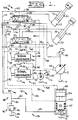
- the fluid system 10 includes a source of pressurized fluid, such as a pump 12, adapted to receive fluid from a reservoir 14, first and second fluid motors, such as hydraulic motors 16,18, and first and second directional control valves 20,22 interposed between the pump 12 and the respective first and second hydraulic cylinders 16,18, and the reservoir 14.
- a source of pressurized fluid such as a pump 12, adapted to receive fluid from a reservoir 14, first and second fluid motors, such as hydraulic motors 16,18, and first and second directional control valves 20,22 interposed between the pump 12 and the respective first and second hydraulic cylinders 16,18, and the reservoir 14.
- Each hydraulic cylinder 16,18 has a head end 23 and a rod end 24.
- Conduits 25,26 connect the pump 12 with the respective first and second directional control valves 20,22.
- Conduits 28,30 connect the first directional control valve 20 to the respective rod end 24 and head end 23 of the first hydraulic cylinder 16.
- Conduits 32,34 connect the second directional control valve 22 with the respective rod end 24
- the pump 12 of the subject arrangement is a variable displacement load responsive pump that is responsive to a load signal for providing the necessary pressurized fluid to the fluid system 10. It is recognized that other types of pumps, such as, fixed displacement or pressure compensated pumps, could be used herein without departing from the essence of the invention.
- each of the first and second directional control valves 20,22 are infinitely variable, hydraulically actuated load responsive control valves. Signal conduits 38,40 respectively connect fluid load signal ports 42,44 of the first and second directional control valves 20,22 to a pump compensator 46 of the pump 12. It is likewise recognized that each of the first and second directional control valves 20,22 could be of a type different from that noted above without departing from the essence of the invention.
- First and second generating means 50,52 such as signal generators 54,56, are provided and operative to provide control signals to operate the respective first and second directional control valves 20,22.
- the first and second signal generators 54,56, of the subject embodiment are hydraulic signal generators and are adapted to receive pressurized fluid from a source of pressurized fluid, such as pump 58, by respective conduits 60,62.
- a conventional pilot relief valve 63 is connected to the conduit 60 and operative to control the maximum pressure level of the fluid therein.
- the first signal generator 54 transmits a first control signal 64 through a conduit 66 to one end of the first directional control valve 22.
- a second control signal 68 generated by the first signal generator 54 is transmitted through a conduit 70 to the other end of the first directional control valve 22.
- the second signal generator 56 transmits a third control signal 72 through a conduit 74 to one end of the second directional control valve 22.
- a fourth control signal 76 generated by the second signal generator 56 is transmitted through a conduit 78 to the other end of the second directional control valve 22.
- Exhaust manifold means 80 is provided in the fluid system 10 between the first and second directional control valve 20,22 and the reservoir 14.
- the exhaust manifold means 80 includes respective exhaust conduits 82,84,86 which connects the outlet flow from each of the first and second directional control valve 20,22 to the reservoir 14.
- the exhaust manifold means 80 also includes selector means 88 located in the exhaust conduits 82,84 for selectively pressurizing the exhaust manifold means 80 during control of the respective first and second hydraulic cylinders 16,18.
- the selector means 88 includes pressure limiting and unloading means 90 for controlling the maximum pressure therein and for selectively unloading or bypassing the fluid flow to the reservoir 14.
- the pressure limiting and unloading means 90 includes pressure limiting means 92, such as a pressure relief valve 94 and control means 96.
- the control means 96 includes a normally-open unloading valve 98 operative in response to receipt of the second or fourth control signal to selectively interrupt the communication of fluid flow between the exhaust manifold means 80 and the reservoir 14.
- the normally-open unloading valve 98 includes a housing 100 having a first piston 102 and a second piston 104 slidably disposed therein.
- the normally-open unloading valve 98 is located in the exhaust conduit 82 and is operative to selectively interrupt flow therein.
- the first piston 102 is operative to interrupt the fluid flow in exhaust conduit 82 in response to receipt of the second control signal 68 through a conduit 106, and is spring biased to an open position in response to the force of a spring 107.
- the second piston 104 is located adjacent the first piston 102 and is operative in response to receipt of the fourth control signal 76 through a conduit 108 to move the first piston 102 to the position to interrupt the flow of fluid in the exhaust conduit 82 and is spring biased to the open position in response to the force of spring 107.
- a first anti-cavitational valve means 109 interconnects the outlet of the first directional control valve 20 and the rod end 24 of the first hydraulic cylinder 16.
- a second anti-cavitational valve means 110 interconnects the outlet of the second directional control valve means 22 and the rod end 24 of the second hydraulic cylinder 18.
- the first anti-cavitational valve means 109 includes a conduit 111 having a check valve 112 disposed therein and connected between the exhaust conduit 82 and the conduit 28.
- the second anti-cavitational valve means 110 includes a conduit 113 having a check valve 114 located therein and connected between the exhaust conduit 86 and the conduit 32.
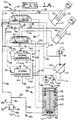
- the control means 96 of Fig. 1A includes a normally-closed unloading valve 116 operative in response to receipt of the first control signal 64 to selectively open communication of fluid flow between the exhaust means 80 and the reservoir 14.
- the normally-closed unloading valve 116 includes a housing 118 having a first piston 120 and a second piston 122 slidably disposed in the housing 118.
- the first piston 120 is operative in response to receipt of the first control signal 64 through a conduit 124 to allow the flow of fluid in the exhaust conduit 82 to flow therethrough.
- the first piston 120 is movable to the closed position by the bias of a spring 126.
- the second piston 122 is located adjacent the first piston 120 and operative in response to receipt of the third control signal 72 through a conduit 128 to move the first piston 120 to an open position.
- a first and second directional control valves 20',22' of Fig. 2 are infinitely variable three position valves which are actuated in response to receipt thereto of an electrical signal.
- a first and second signal generators 54',56' are electrical signal generators which receive their source of electrical energy from an electrical source 130 through an electrical line 132.
- Each of the first and second directional control valves 20',22' is connected to the pump 12 and to the respective head ends 23 and rod ends 24 of the first and second hydraulic cylinders 16,18 as previously set forth in Figs. 1 and 1A. Likewise, the exhaust fluid from the first and second directional control valves 20',22' is directed to the reservoir 14 through the exhaust conduits 82,84.
- the first electrical signal generator 54' is operative to generate a first control signal 64' which is directed to one end of the first directional control valve 20' by an electrical line 134 and a second control signal 68' is directed to the other end of the first directional control valve 20' through an electrical line 136.
- the second electrical signal generator 56' generates a third control signal 72' and directs it to the first end of the second directional control valve 22' through an electrical line 138, and a fourth control signal 76' is directed to the other end of the second directional control valve 22' by an electrical line 140.
- the control means 96 of this embodiment includes a normally-open unloading valve 98' which is operative to interrupt the return flow in the conduit 82 to the reservoir 14 in response to receipt of the second or fourth control signals 68',76'.
- the normally-open unloading valve 98' includes a housing 144 having a piston 146 slidably disposed therein. The piston 146 is movable to the closed position in response to a coil 148 receiving an electrical signal. The coil 148 is connected to the second control signal 68' by an electrical line 150 and also connected to the fourth control signal 76' by an electrical line 152.
- the coil 148 is a part of a solenoid which is an electromechanical device well known in the art to produce a force upon receipt of an electrical signal to move an armature.
- a portion of the piston 146 serves as the armature.
- the piston 146 Upon receipt of the second or fourth electrical control signals 68',76', the piston 146 is moved to the closed position to interrupt the return flow of fluid in the exhaust conduit 82 to the reservoir 14.
- a normally-open unloading valve 98' of the subject arrangement could also be normally-closed unloading valve and be operative to the open position in response to the first or third electrical control signals 64',72' without departing from the essence of the invention.
- a signal converter 153 is provided.
- the signal converter 153 may be utilized in a system having both the hydraulic signal generator 54 or 56 and the electrically responsive normally-open unloading valve 98'.
- the signal generator 153 includes a housing 154 having an inlet port 155 and a piston 156 slidably disposed in the housing 154.
- the piston 156 is spring biased to a first position in response to a spring 157 and movable toward a second position in response to a hydraulic signal received at the inlet port 155.
- the housing 154 also includes a rheostat 158 responsive to movement of the piston 156 to regulate an electrical signal received at an inlet connection 159 and to pass the regulated electrical signal to an outlet connection 160.
- the first and second directional control valves illustrated in Fig. 1 are hydraulically actuated and are of a spool type wherein the first and second directional control valves 20',22' of Fig. 2 are electrically actuated and are likewise of the spool type.
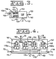
- the directional control valve illustrated in Fig. 4 is a poppet directional control valve and can be readily substituted for the spool type valves in Figs. 1, 1A, and 2.
- the poppet type directional control valve 161 includes a housing 162 having first, second, third, and fourth normally-closed poppet valves 164,166,168,170 disposed therein.
- Each of the poppet valves 164,166,168,170 are spring biased to the closed position and movable to the open position in response to a control signal being received by respective first, second, third, and fourth controllers 164a,166a,168a,170a.
- the housing 162 also includes first and second signal control connections 172,174, a pump inlet port 176, a fluid exhaust port 178, and first and second cylinder ports 180,182.
- the exhaust manifold means 80, the first and second anti-cavitational valves means 109,110, and the first and second generating means 50,52 make up an exhaust pressurizing control 184 for use in the fluid system 10.
- the first control signal 64 is generated and directed to one end of the directional control valve 20 moving it to its actuated position to direct pressurized fluid from the pump 12 to the head end 23 of the first hydraulic cylinder 16.
- the pressurized fluid moves the resisting type load W 1 upwardly and the fluid exiting from the rod end 24 of the hydraulic cylinder 16 is directed through conduit 28 across the directional valve 20 to the exhaust conduit 82.
- the return flow in conduit 82 is directed simultaneously to the relief valve 94 and the normally-open unloading valve 98. Since the unloading valve 98 is open, the fluid flow in the conduit 82 passes freely to the reservoir 14.
- the directional control valve 20 Upon movement by the operator of the first signal generator 54 to a position to generate the second control signal 68, the directional control valve 20 is moved to its second operative position to direct pressurized fluid through the conduit 28 to the rod end of the first hydraulic cylinder 16.
- the load W 1 is an aiding type load.
- the fluid from the head end 23 of the first hydraulic cylinder 16 is directed through conduit 30 across the first directional control valve 20 to the exhaust conduit 82.
- the load W 1 is an aiding type load, the fluid flow out of the head end 23 thereof exhausts so quickly, that the quantity of fluid entering the rod end 24 thereof through the conduit 28 from the pump 12 is not sufficient to keep the rod end 24 filled. Consequently, cavitation or a negative pressure condition exists in the rod end 24.
- the second control signal 68 is simultaneously directed to the first piston 102 of the normally-opened unloading valve 98.
- the piston 102 of the normally-open unloading valve 98 moves to the closed position which interrupts the flow of fluid in the exhaust conduit 82 to the reservoir 14. Since the return flow through the exhaust conduit 82 is blocked, the fluid flow in the exhaust conduit 82 must pass through the exhaust conduit 84 to the relief valve 94. The pressure in the exhaust conduit 82 builds until the predetermined pressure level of the relief valve 94 is achieved, wherein the fluid flow passes through the exhaust conduit 84 to the reservoir 14.
- the fluid pressure in the exhaust conduit 82 is at the level established by the relief valve 94.
- the pressurized fluid in exhaust conduit 82 is available through the conduit 111 and one-way check valve 112 to the conduit 28 and subsequently to the rod end 24 of the first hydraulic cylinder 16. Consequently, the return fluid flow from the head end 24 thereof is directed through the conduit 82 and the anti-cavitational valve means 109 to maintain the fluid pressure in the rod end 24 at a level equivalent to the predetermined pressure setting of the relief valve 94.
- the second directional control valve 22 Upon movement by the operator of the second signal generator 56 to produce the third control signal 72, the second directional control valve 22 is moved to its first operative position. Pressurized fluid is directed from the pump 12 to the head end 23 of the second hydraulic cylinder 18 to move the second resisting type load W 2 . The exhaust flow from the rod end 24 thereof is directed through conduit 30 and across the second directional control valve 22 to the exhaust conduit 86 and subsequently to the exhaust conduit 82. This exhausted fluid flow is returned to the reservoir 14 across the normally-open unloading valve 98. Movement by the operator of the second signal generator 56 to the other operative position generates the fourth control signal 76.
- the fourth control signal 76 is directed to the other end of the second directional control valve 22 moving it to its second operative position wherein fluid flow from the pump 12 is directed through the conduit 32 to the rod end 24 of the second hydraulic cylinder 18 thus moving the aiding type load W 2 in a downward direction.
- the exhaust fluid from the head end 23 thereof is directed through conduit 34 across directional control valve 22 to the exhaust conduit 86 and consequently to the return conduit 82. Since the pressurized fluid is being directed to the rod end 24 of the second hydraulic cylinder 18 and the load W 2 is an aiding type load, the exhaust flow from the head end 23 thereof is exhausting at a rate faster than the rate of the fluid flow coming into the rod end 24 thereof. Consequently, cavitation exists in the rod end 24 of the second hydraulic cylinder 18.
- the fourth control signal 76 is directed to the second piston 104 of the normally-open unloading valve 98.
- the fourth control signal 76 acting on the second piston 104 moves the second piston 104 against the first piston 102 to move the first piston 102 to its closed position, thus, blocking fluid flow in the return conduit 82.
- the fluid flow exhaust conduit 82 is forced to flow through the conduit 84 across the relief valve 94 to the reservoir 14.
- the pressurized fluid now present in the exhaust conduit 86 is directed through conduit 113 and one-way check valve 114 to the conduit 32 and subsequently to the rod end 24 of the second hydraulic cylinder 18.
- the pressurized fluid in the rod end 24 thereof effectively eliminates the cavitation that would otherwise exist therein and add stiffness to the second hydraulic cylinder which offsets any lag in the system and/or rebound upon the load W 2 reaching a position of resistance.
- the operation of the system is substantially the same as the operation of the system previously set forth in Fig. 1.
- the control means 96 is a normally-closed unloading valve 116. Consequently, upon movement of the first signal generator 54 by the operator to generate the first control signal 64, the first control signal 64 moves the first directional control valve 20 to its first operative position directing pressurized fluid to the head end 23 of the first hydraulic cylinder 16 to raise the resisting type load W 1 . The return fluid from the rod end 24 thereof is directed through conduit 28 across the first directional control valve 20 to the exhaust conduit 82.
- the exhaust return flow in exhaust conduit 82 is simultaneously directed to the normally-closed unloading valve 116 and to the relief valve 94. Since the normally-closed unloading valve 116 has the flow in exhaust conduit 82 interrupted, the fluid flow must pass across the relief valve 94. Consequently, a positive pressure is provided in the exhaust conduit 82. This pressurized fluid in the exhaust conduit 82 is not needed during the raising of the resisting type load W 1 . Therefore, it is desirable to eliminate the pressure in the exhaust conduit 82.
- the first control signal 64 is directed to act on the first piston 120 of the normally-closed unloading valve 116 to move the first piston 120 to an open position allowing free flow of the fluid in the exhaust conduit 82 to the reservoir 14.
- the first directional valve 20 is moved to its second actuated position wherein the pressurized fluid from the pump 12 is directed to the rod end 24 of the first hydraulic cylinder 16 through the conduit 28 to move the aiding type load W 1 downwardly.
- the return fluid from the head end 23 thereof is directed through conduit 30 across the first directional control 20 to the exhaust conduit 82.
- the return flow in the exhaust conduit 82 is simultaneously directed to the relief valve 94 and the normally-closed unloading valve 116. Since the unloading valve 116 is normally closed, the fluid flow in the exhaust conduit 82 is interrupted and the fluid flow must flow across the relief valve 94.
- the pressurized fluid now in the exhaust conduit 82 is directed through the conduit 111 and the one-way check valve 112 to the conduit 28 and subsequently to the rod end 24 of the first hydraulic cylinder 16.
- the pressurized fluid directed to the rod end 24 thereof not only eliminates any possibility of cavitation existing in the rod end 24 during downward movement of the aiding type load W 1 , but maintains a pressure in the rod end 24 to a level as determined by the setting of the pressure relief valve 94.
- the second directional control valve 22 Upon movement by the operator of the second signal generator 54 to the position to generate the third control signal 72, the second directional control valve 22 is moved to its first operative position to connect the pressurized fluid from the pump 12 to the head end 23 of the second hydraulic cylinder 18 to raise the resisting type load W 2 .
- the third control signal 72 is simultaneously directed to the normally-closed unloading valve 116 and acts against the second piston 122 to move the second piston 122 against the first piston 120 causing the first piston to move to an open position. This allows free fluid flow through the exhaust conduit 82 to the reservoir 14. Since the pressurized fluid from the pump 12 is raising a resisting type load W 2 , the exhaust fluid from the rod end 24 thereof is directed through the conduit 32 across the second directional control valve 22 to the conduits 86,82 to freely flow to the reservoir 14.
- the second directional control valve 22 moves to its second operative position to connect pressurized fluid from the pump 12 to the rod end 24 of the second hydraulic cylinder 18 to move the aiding type load W 2 in a downward direction.
- the exhaust fluid exiting from the head end 23 thereof flows through the conduit 34 across the second directional control valve 22 to the exhaust conduit 86 and exhaust conduit 82 simultaneously to the relief valve 94 and the normally-closed unloading valve 116. Since the unloading valve 116 is normally closed, the fluid flow must pass across the relief valve 94 to the reservoir 14.
- conduit 86 is pressurized and the pressurized fluid in conduit 86 is directed through conduit 113 and check valve 114 to the conduit 32 and subsequently to the rod end 24 of the second hydraulic cylinder 18.
- the pressurized fluid being subjected to the rod end 24 thereof eliminates any possibility of cavitation existing therein.
- first and second directional control valves 20',22' of Fig. 2 are controlled by the first, second, third, and fourth electric control signals which are being generated by first and second electrical signal generators 54'56', and the normally-open unloading valve 98' is movable to the closed position in response to receipt of an electrical control signal.
- the second control signal 68' is likewise directed to the normally-open unloading valve 98'.
- the second control signal 68' acting on the coil 148 moves the normally-open unloading valve 98' to its closed position to interrupt the flow of fluid in the exhaust conduit 82 to the reservoir 14.
- the normally-open unloading valve 98' closed the fluid flow in exhaust conduit 82 must pass across the relief valve 94 which maintains a positive pressure in the exhaust conduit 82.
- the pressurized fluid in the exhaust conduit 82 is directed through the conduit 111 and the one-way check 112 to the rod end 24 of the first hydraulic cylinder 16 to eliminate any possibility of cavitation therein due to the lowering of the aiding type load W 1 .
- the fourth control signal 76' acts on the coil 148 of the normally-open unloading valve 98' to interrupt the flow of fluid in the exhaust conduit 82 to the reservoir 14. Consequently, the flow must pass across the relief valve 94 which maintains the positive pressure in the exhaust conduits 82,86.
- the pressurized fluid in the exhaust conduit 86 is directed through the conduit 113 and one-way check valve 114 to the rod end 24 of the second hydraulic cylinder 18 to effectively eliminate any possibilities of cavitation therein.
- the signal convertor 153 can be installed in a system so that hydraulic signal generators 54,56 may be used in combination with electrically actuated unloading valves 98'.
- the inlet port 155 of the signal converter 153 is connected to the hydraulically generated second control signal 68 through conduit 106 and the pressurized fluid therein acts against the piston 156 thereof to convert the hydraulic signal 106 to an electrical signal.
- the source of electrical energy 130 is connected to the inlet connection 159 of the the rheostat 158 by the conduit 132 and the regulated electrical signal is transmitted to the outlet connection 160 to which electrical line 150 is connected. Consequently, in the embodiment set forth in Fig. 1, the hydraulically generated control signals can be converted into electrical control signals by use of two signal converters to control the operation of an electrically responsive unloading valve 98'.
- the poppet type directional control valve 161 can be readily substituted for the spool type directional control valves 20,22,20',22' described above.
- Fig. 1 will be used as an example.
- the poppet type directional control valve 161 of Fig. 4 will be substituted for the spool type directional control valve 20 of Fig. 1.
- the conduit 25 from the pump 12 is in communication with the first and second poppet type valves 164,166 through the pump inlet port 176 and the exhaust conduit 82 is in communication with the third and fourth poppet type valves 168,170 through the fluid exhaust port 178.
- the rod end 24 of the first hydraulic cylinder 16 is in communication with the first and third poppet type valves 164,168 through the first cylinder port 180.
- the conduit 30 connects the head end 23 of the first hydraulic cylinder 16 with the second and fourth poppet type valves 166,170 through the cylinder port 182.
- the first control signal 64 is connected through conduit 66 and the first signal control connection 172 to the second and third controllers 166a,168a.
- the second control signal 70 is connected by the conduit 70 and the second signal control connection 174 to the first and fourth controllers 164a,170a.
- the second and third poppet type valves 166,168 are opened allowing the flow from the pump 12 to be directed to the head end 23 of the first cylinder type fluid motor 16 and the exhaust flow from the rod end 24 is directed to the third poppet type valve 68 and thereacross to the exhaust conduit 82.
- the first and fourth poppet type valves 164,170 are opened allowing the pressurized fluid from the pump 12 to be directed to the rod end 24 of the first hydraulic cylinder 16 and the return flow therefrom is directed to the fourth poppet type valve 170 and thereacross to the exhaust conduit 82.
- the second and third poppet type valves 166,168 are being opened by the first control signal 66 being directed to the second and third controllers 166a,168a, the first and fourth poppet type valves remain closed due to the absence of a control signal being directed to the first and fourth controllers 164a,170a.
- the exhaust pressurizing control 184 of the fluid system 10 as set forth in the above described embodiments provides an arrangement that eliminates cavitation in the first and second hydraulic cylinders 16,18 during lowering of aiding type loads W 1 ,W 2 .
- the elimination of cavitation in the hydraulic cylinders 16,18 and the adding of a positive pressure therein provides better stiffness in the hydraulic cylinders during operation. This stiffness eliminates both time lag in the system and the possibility of load rebound once the load W 1 /W 2 reaches the position of resistance.
Landscapes
- Engineering & Computer Science (AREA)
- General Engineering & Computer Science (AREA)
- Physics & Mathematics (AREA)
- Fluid Mechanics (AREA)
- Mechanical Engineering (AREA)
- Mining & Mineral Resources (AREA)
- Civil Engineering (AREA)
- Structural Engineering (AREA)
- Chemical & Material Sciences (AREA)
- Analytical Chemistry (AREA)
- Fluid-Pressure Circuits (AREA)
Claims (29)
- Auslaßdrucksteuerung (184), die zur Verwendung in einem Strömungsmittelsystem (10) geeignet ist, und zwar mit einem Strömungsmittelmotor (16), der alternativ einer Ein-Richtungs-Positivlast (W1) und einer Ein-Richtungs-Negativlast (W1) unterworfen ist, wobei das Strömungsmittelsystem (10) eine Pumpe (12), ein Reservoir bzw. einen Tank (14) und ein Wegeventil (20) aufweist, das betätigbar ist, um selektiv bzw. wahlweise den Strömungsmittelmotor (16) mit der Pumpe (12) und dem Resevoir (14) zu verbinden, wobei die Auslaßdrucksteuerung (184) folgendes vorsieht:Auslaßsammelleitungsmittel (80), die zwischen dem Wegeventil (20) und dem Reservoir (14) angeordnet sind;Anti-Kavitations-Ventilmittel (109), die zwischen den Auslaßsammelleitungsmitteln (80) und dem Strömungsmittelmotor (16) angeordnet sind;Mittel (50) zu Erzeugen eines ersten Steuersignals (64), um durch das Wegeventil (20) die Bewegung der Ein-Richtungs-Positivlast (W1) zu steuern, und zum Erzeugen eines zweiten Steuersignals (68), um durch das Wegeventil (20) die Bewegung der Ein-Richtungs-Negativlast (W1) zu steuern; undwobei die Auslaßsammelleitungsmittel (80) zweite Auswahlmittel (88) besitzen, zum Unterdrucksetzen der Auslaßsammelleitungsmittel (80), während der Steuerung der Ein-Richtungs-Negativlast (W1), und um die Auslaßsammelleitungsmittel (80) vom Druck zu entlasten, und zwar während der Steuerung der Ein-Richtungs-Positivlast (W1), wobei die Auswahlmittel (88) auf die ersten und zweiten Steuersignale (64, 68) ansprechen.
- Auslaßdrucksteuerung (184) nach Anspruch 1, wobei die Auswahlmittel (88) Druckbegrenzungs- und Entlastungsmittel (90) aufweisen.
- Auslaßdrucksteuerung (184) nach Anspruch 2, wobei die Druckbegrenzungs- und Entlastungsmittel (90) Steuermittel (96) aufweisen zum Unterbrechen der Verbindung von Strömungsmittelfluß zwischen den Auslaßsammelleitungsmitteln (80) und dem Reservoir (14), und zwar während der Steuerung der Ein-Richtungs-Negativlast (W1).
- Auslaßdrucksteuerung (184) nach Anspruch 3, wobei die Steuermittel (96) die Verbindung von Strömungsmittelfluß zwischen den Auslaßsammelleitungsmitteln (80) und dem Reservoir (14) öffnen, und zwar während der Steuerung der Ein-Richtungs-Positivlast (W1).
- Auslaßdrucksteuerung (184) nach Anspruch 4, wobei die Steuermittel (96) auf eines der ersten und zweiten Steuersignale (64, 68) ansprechen.
- Auslaßdrucksteuerung (184) nach Anspruch 5, wobei die Druckbegrenzungs- und Entlastungsmittel (90) Druckbegrenzungsmittel (92) aufweisen.
- Auslaßdrucksteuerung (184) nach Anspruch 6, wobei die Druckbegrenzungsmittel (92) ein Druckbegrenzungsventil (94) sind.
- Auslaßdrucksteuerung (184) nach Anspruch 6, wobei die Steuermittel (96) ein normalerweise geöffnetes Entlastungsventil (98) aufweisen.
- Auslaßdrucksteuerung (184) nach Anspruch 8, wobei das normalerweise geöffnete Entlastungsventil (98) in die geöffnete Position federvorgespannt ist, und in die geschlossene Position beweglich ist, und zwar ansprechend auf das zweite Steuersignal (68).
- Auslaßdrucksteuerung (184) nach Anspruch 9, wobei der Strömungsmittelmotor (16) ein Hydraulikzylinder ist, und wobei das normalerweise geöffnete Entlastungsventil (98) ein Gehäuse (100) aufweist, und zwar mit einem Kolben (102), der darin gleitend angeordnet ist, und ansprechend auf den Empfang des zweiten Steuersignals (68) betätigbar ist, um selektiv die Verbindung von Strömungsmittelfluß zwischen den Auslaßsammelleitungsmitteln (80) und dem Reservoir (14) zu unterbrechen.
- Auslaßdrucksteuerung (184) nach Anspruch 6, wobei das Strömungsmittelsystem (10) einen zweiten Strömungsmittelmotor (18) besitzt, der alternativ einer zweiten Ein-Richtungs-Positivlast (W2) und einer zweiten Ein-Richtungs-Negativlast (W2) unterworfen ist, und mit einem zweiten Wegeventil (22), das betätigbar ist, um selektiv den zweiten Strömungsmittelmotor (18) mit der Pumpe (12) und dem Reservoir (14) zu verbinden, und wobei die Auslaßsammelleitungsmittel (80) zwischen dem zweiten Wegeventil (22) und den Reservoir (14) angeordnet sind, wobei die zweiten Anti-Kavitations-Ventilmittel (110) zwischen dem Auslaßsammelleitungsmitteln (80) und dem zweiten Strömungsmittelmotor (18) angeordnet sind, wobei zweite Mittel (52) vorgesehen sind zum Erzeugen eines dritten Steuersignals (72), um durch das zweite Wegeventil (22) die Verschiebung der zweiten Ein-Richtungs-Positivlast (W2) zu steuern, und zum Erzeugen eines vierten Steuersignals (76), um durch das zweite Wegeventil (22) die Verschiebung der zweiten Ein-Richtungs-Negativlast (W2) zu steuern, wobei die Steuermittel 96 auf eines der dritten und vierten Steuersignale (72, 76) ansprechen, um die Verbindung von Strömungsmittelfluß zwischen den Auslaßsammelleitungsmitteln (80) und dem Reservoir bzw. Tank (14) zu unterbrechen, und zwar während der Steuerung der zweiten Ein-Richtungs-Negativlast (W2).
- Auslaßdrucksteuerung (184) nach Anspruch 11, wobei die Steuermittel (96) die Verbindung von Strömungsmittelfluß zwischen den Auslaßsammelleitungsmitteln (80) und dem Reservoir (14) öffnen, und zwar während der Steuerung der zweiten Ein-Richtungs-Positivlast (W2).
- Auslaßdrucksteuerung (184) nach Anspruch 12, wobei die Steuermittel (96) auf das vierte Steuersignal (76) ansprechen.
- Auslaßdrucksteuerung (184) nach Anspruch 13, wobei die Steuermittel (96) ein normalerweise geöffnetes Entlastungsventil (98) aufweisen.
- Auslaßdrucksteuerung (184) nach Anspruch 14, wobei das normalerweise geöffnete Entlastungsventil (98) in die offene Position federvorgespannt ist, und in die geschlossene Position beweglich ist, und zwar ansprechend auf die zweiten oder vierten Steuersignale (68, 76).
- Auslaßdrucksteuerung (184) nach Anspruch 15, wobei die ersten und zweiten Strömungsmittelmotoren (16, 18) Hydraulikzylinder sind, und wobei das normalerweise geöffnete Entlastungsventil (98) ein Gehäuse (100) aufweist, und zwar mit einem ersten Kolben (102), der darin gleitend angeordnet ist, und betätigbar ansprechend auf den Empfang des zweiten Steuersignals (68), um selektiv die Verbindung von Strömungsmittelfluß zwischen den Auslaßsammelleitungsmitteln (80) und dem Reservoir (14) zu unterbrechen, und mit einem zweiten Kolben (104), der gleitend im Gehäuse (100) benachbart zum ersten Kolben (102) angeordnet ist, und ansprechend auf den Empfang des vierten Steuersignals (76) betätigbar ist, um den ersten Kolben (102) zu bewegen, um die Verbindung von Strömungsmittelfluß zwischen den Auslaßsammelleitungsmitteln (80) und dem Reservoir (14) zu unterbrechen.
- Auslaßdrucksteuerung (184) nach Anspruch 16, wobei die ersten und zweiten Erzeugungsmittel (50, 52) hydraulische Signalgeneratoren bzw. Signalerzeuger (54, 56) sind, die mit einer Quelle (58) von unter Druck gesetztem Strömungsmittel verbunden sind, und wobei die ersten und zweiten Wegeventile (20, 22) durch hydraulische Steuersignale betätigt werden.
- Auslaßdrucksteuerung (184) nach Anspruch 16, wobei die ersten und zweiten Erzeugungsmittel (50, 52) elektrische Signalgeneratoren (54', 56') sind, die mit einer Quelle (130) von elektrischer Energie verbunden sind, und wobei die ersten und zweiten Wegeventile (20', 22') durch elektrische Steuersignale betätigt werden.
- Auslaßdrucksteuerung (184) nach Anspruch 16, wobei die ersten und zweiten Wegeventile (20, 22) Ventile der Kolbenbauart bzw. Kolbenventile sind.
- Auslaßdrucksteuerung (184) nach Anspruch 16, wobei die ersten und zweiten Wegeventile (20, 22) Ventile (161) der Sitzbauart bzw. Sitzventile sind.
- Auslaßdrucksteuerung (184) nach Anspruch 6, wobei die Steuermittel (96) ein normalerweise geschlossenes Entlastungsventil (116) aufweisen.
- Auslaßdrucksteuerung (184) nach Anspruch 21, wobei das normalerweise geschlossene Entlastungsventil (116) in die geschlossene Position federvorgespannt ist, und in die offene Position ansprechend auf das erste Steuersignal (64) beweglich ist.
- Auslaßdrucksteuerung (184) nach Anspruch 22, wobei das normalerweise geschlossene Entlastungsventil (116) ein Gehäuse (118) aufweist, und zwar mit einem Kolben (120), der darin gleitend angeordnet ist, und der ansprechend auf den Empfang des ersten Steuersignals (64) betätigbar ist, um selektiv die Verbindung von Strömungsmittelfluß zwischen den Auslaßsammelleitungsmitteln (80) und dem Tank (14) zu öffnen.
- Auslaßdrucksteuerung (184) nach Anspruch 23, wobei das Strömungsmittelsystem (10) einen zweiten Strömungsmittelmotor (18) der Zylinderbauart besitzt, der alternativ einer zweiten Ein-Richtungs-Positivlast (W2) und einer zweiten Ein-Richtungs-Negativlast (W2) unterworfen ist, und ein zweites Wegeventil (22), das betätigbar ist, um selektiv den zweiten Strömungsmittelmotor (18) mit der Pumpe (12) und dem Tank (14) zu verbinden, und wobei die Auslaßsammelleitungsmittel (80) zwischen dem zweiten Wegeventil (22) und dem Reservoir (14) angeordnet sind, wobei zweite Anti-Kavitations-Mittel (110) zwischen den Auslaßsammelleitungsmitteln (80) und dem zweiten Strömungsmittelmotor (18) angeordnet sind, wobei zweite Mittel (52) vorgesehen sind zum Erzeugen eines dritten Steuersignals (72), um durch das zweite Wegeventil (22) die Verschiebung der zweiten Ein-Richtungs-Positivlast (W2) zu steuern, und zum Erzeugen eines vierten Steuersignals (76), um durch das zweite Dichtungssteuerventil (22) die Verschiebung der zweiten Ein-Richtungs-Negativlast (W2) zu steuern, wobei die Steuermittel (96) auf eines der dritten und vierten Steuersignale (72, 76) ansprechen, um die Verbindung von Strömungsmittelfluß zwischen den Auslaßsammelleitungsmitteln (80) und dem Tank (14) zu öffnen, und zwar während der Steuerung der zweiten Ein-Richtungs-Positivlast (W2).
- Auslaßdrucksteuerung (184) nach Anspruch 24, wobei die Steuermittel (96) die Verbindung von Strömungsmittelfluß zwischen den Auslaßsammelleitungsmitteln (80) und dem Reservoir (14) unterbrechen, und zwar während der Steuerung der zweiten Ein-Richtungs-Negativlast (W2).
- Auslaßdrucksteuermittel (184) nach Anspruch 25, wobei ein zweiter Kolben (122) gleitend im Gehäuse (118) angeordnet ist, und zwar benachbart zum ersten Kolben (120), und ansprechend auf den Empfang des dritten Steuersignals (72) betätigbar ist, um den ersten Kolben (120) zu bewegen, um die Verbindung von Strömungsmittelfluß zwischen den Auslaßsammelleitungsmitteln (80) und dem Reservoir (14) zu öffnen.
- Auslaßdrucksteuerung (184) nach Anspruch 26, wobei die ersten und zweiten Strömungsmittelmotoren (16, 18) Hydraulikzylinder sind.
- Auslaßdrucksteuerung (184) nach Anspruch 6, wobei die Erzeugungsmittel (50) ein Hydrauliksignalgenerator (54) sind, der mit einer Quelle (58) von unter Druck gesetzten Strömungsmittel verbunden ist, und wobei das Wegeventil (20) durch hydraulische Steuersignale betätigt wird.
- Auslaßdrucksteuerung (184) nach Anspruch 6, wobei die Erzeugungsmittel (50) ein elektrischer Signalgenerator (54') sind, der mit einer Quelle (130) von elektrischer Energie verbunden ist, und wobei das Wegeventil (20') durch elektrische Steuersignale betätigt wird.
Applications Claiming Priority (3)
| Application Number | Priority Date | Filing Date | Title |
|---|---|---|---|
| US07/609,348 US5044256A (en) | 1990-11-05 | 1990-11-05 | Exhaust pressurizing control for a fluid system |
| US609348 | 1990-11-05 | ||
| PCT/US1991/000339 WO1992008055A1 (en) | 1990-11-05 | 1991-01-22 | Exhaust pressurizing control for a fluid system |
Publications (3)
| Publication Number | Publication Date |
|---|---|
| EP0565645A1 EP0565645A1 (de) | 1993-10-20 |
| EP0565645A4 EP0565645A4 (de) | 1994-04-13 |
| EP0565645B1 true EP0565645B1 (de) | 1996-09-04 |
Family
ID=24440411
Family Applications (1)
| Application Number | Title | Priority Date | Filing Date |
|---|---|---|---|
| EP92909590A Expired - Lifetime EP0565645B1 (de) | 1990-11-05 | 1991-01-22 | Auslassdrucksteuerung fuer ein fluidsystem |
Country Status (6)
| Country | Link |
|---|---|
| US (1) | US5044256A (de) |
| EP (1) | EP0565645B1 (de) |
| AU (1) | AU1651492A (de) |
| CA (1) | CA2082931A1 (de) |
| DE (1) | DE69121908T2 (de) |
| WO (1) | WO1992008055A1 (de) |
Families Citing this family (7)
| Publication number | Priority date | Publication date | Assignee | Title |
|---|---|---|---|---|
| US5275086A (en) * | 1992-08-27 | 1994-01-04 | Unlimited Solutions, Inc. | Fluid actuator with internal pressure relief valve |
| US8215107B2 (en) * | 2010-10-08 | 2012-07-10 | Husco International, Inc. | Flow summation system for controlling a variable displacement hydraulic pump |
| US10550868B2 (en) * | 2015-04-10 | 2020-02-04 | Volvo Construction Equipment Ab | Load sensing hydraulic system for a working machine, and a method for controlling a load sensing hydraulic system |
| JP6909743B2 (ja) * | 2018-02-26 | 2021-07-28 | 株式会社東芝 | 蒸気弁駆動装置 |
| CN110645213A (zh) * | 2019-09-06 | 2020-01-03 | 湖南星邦重工有限公司 | 一种底架主动浮动控制方法和控制系统及其高空作业平台 |
| CN115667733A (zh) * | 2020-05-22 | 2023-01-31 | 沃尔沃建筑设备公司 | 液压机 |
| EP4467819B1 (de) * | 2023-05-23 | 2025-07-16 | Danfoss Power Solutions ApS | Hydraulische anordnung |
Family Cites Families (6)
| Publication number | Priority date | Publication date | Assignee | Title |
|---|---|---|---|---|
| US3472127A (en) * | 1967-12-12 | 1969-10-14 | Caterpillar Tractor Co | Control circuit for bulldozers used in pushing |
| US3998134A (en) * | 1974-11-08 | 1976-12-21 | Tadeusz Budzich | Load responsive fluid control valves |
| US4140152A (en) * | 1976-08-20 | 1979-02-20 | Tadeusz Budzich | Load responsive valve assemblies |
| US4222409A (en) * | 1978-10-06 | 1980-09-16 | Tadeusz Budzich | Load responsive fluid control valve |
| US4267860A (en) * | 1978-10-24 | 1981-05-19 | Tadeusz Budzich | Load responsive valve assemblies |
| US4249570A (en) * | 1979-06-18 | 1981-02-10 | Tadeusz Budzich | Exhaust pressurization of load responsive system |
-
1990
- 1990-11-05 US US07/609,348 patent/US5044256A/en not_active Expired - Fee Related
-
1991
- 1991-01-22 EP EP92909590A patent/EP0565645B1/de not_active Expired - Lifetime
- 1991-01-22 WO PCT/US1991/000339 patent/WO1992008055A1/en not_active Ceased
- 1991-01-22 AU AU16514/92A patent/AU1651492A/en not_active Abandoned
- 1991-01-22 CA CA002082931A patent/CA2082931A1/en not_active Abandoned
- 1991-01-22 DE DE69121908T patent/DE69121908T2/de not_active Expired - Fee Related
Also Published As
| Publication number | Publication date |
|---|---|
| US5044256A (en) | 1991-09-03 |
| WO1992008055A1 (en) | 1992-05-14 |
| DE69121908T2 (de) | 1997-01-23 |
| CA2082931A1 (en) | 1992-05-06 |
| EP0565645A1 (de) | 1993-10-20 |
| EP0565645A4 (de) | 1994-04-13 |
| AU1651492A (en) | 1992-05-26 |
| DE69121908D1 (de) | 1996-10-10 |
Similar Documents
| Publication | Publication Date | Title |
|---|---|---|
| EP0525118B1 (de) | Hydraulischer kreislauf und steuervorrichtung dafür | |
| US4977928A (en) | Load sensing hydraulic system | |
| US5220862A (en) | Fluid regeneration circuit | |
| JPS6246724B2 (de) | ||
| EP0621925B1 (de) | Hydaulisches steuersystem mit pilz und kolbenschieberventilen | |
| US5878569A (en) | Energy conversion system | |
| USRE38355E1 (en) | Electrohydraulic control device for double-acting consumer | |
| CN112714831B (zh) | 液压阀装置 | |
| EP0532502A1 (de) | Negativen lastdruck und energie ausnutzendes system. | |
| US4353289A (en) | Power transmission | |
| JPS6110101A (ja) | 液圧制御装置 | |
| EP0565645B1 (de) | Auslassdrucksteuerung fuer ein fluidsystem | |
| JPH0445711B2 (de) | ||
| US20050257519A1 (en) | Hydraulic valve arrangement | |
| US7426884B2 (en) | Circuit arrangement | |
| JPS5997304A (ja) | 伝動装置 | |
| GB2358044A (en) | Hydraulic circuit having pressure equalization during regeneration | |
| US7540231B2 (en) | Control valve device for the control of a consumer | |
| US20180073524A1 (en) | Hydraulic actuator control system | |
| WO1988008931A1 (en) | Load responsive system having synchronizing systems between positive and negative load compensation | |
| JP3942840B2 (ja) | 油圧差動装置 | |
| GB2234297A (en) | Load-independent control device for hydraulic consuming devices | |
| EP0704630A2 (de) | Variables Folgeventil für schwere Baumaschinen | |
| RU2205301C2 (ru) | Гидросистема | |
| US5481874A (en) | Exhaust pressurizing circuit including flow amplification |
Legal Events
| Date | Code | Title | Description |
|---|---|---|---|
| PUAI | Public reference made under article 153(3) epc to a published international application that has entered the european phase |
Free format text: ORIGINAL CODE: 0009012 |
|
| 17P | Request for examination filed |
Effective date: 19921118 |
|
| AK | Designated contracting states |
Kind code of ref document: A1 Designated state(s): DE FR GB |
|
| A4 | Supplementary search report drawn up and despatched |
Effective date: 19940225 |
|
| AK | Designated contracting states |
Kind code of ref document: A4 Designated state(s): DE FR GB |
|
| GRAG | Despatch of communication of intention to grant |
Free format text: ORIGINAL CODE: EPIDOS AGRA |
|
| 17Q | First examination report despatched |
Effective date: 19951211 |
|
| GRAH | Despatch of communication of intention to grant a patent |
Free format text: ORIGINAL CODE: EPIDOS IGRA |
|
| GRAH | Despatch of communication of intention to grant a patent |
Free format text: ORIGINAL CODE: EPIDOS IGRA |
|
| GRAA | (expected) grant |
Free format text: ORIGINAL CODE: 0009210 |
|
| AK | Designated contracting states |
Kind code of ref document: B1 Designated state(s): DE FR GB |
|
| PG25 | Lapsed in a contracting state [announced via postgrant information from national office to epo] |
Ref country code: FR Effective date: 19960904 |
|
| REF | Corresponds to: |
Ref document number: 69121908 Country of ref document: DE Date of ref document: 19961010 |
|
| PGFP | Annual fee paid to national office [announced via postgrant information from national office to epo] |
Ref country code: DE Payment date: 19961128 Year of fee payment: 7 |
|
| PG25 | Lapsed in a contracting state [announced via postgrant information from national office to epo] |
Ref country code: GB Effective date: 19970122 |
|
| EN | Fr: translation not filed | ||
| PLBE | No opposition filed within time limit |
Free format text: ORIGINAL CODE: 0009261 |
|
| 26N | No opposition filed | ||
| GBPC | Gb: european patent ceased through non-payment of renewal fee |
Effective date: 19970122 |
|
| PG25 | Lapsed in a contracting state [announced via postgrant information from national office to epo] |
Ref country code: DE Free format text: LAPSE BECAUSE OF NON-PAYMENT OF DUE FEES Effective date: 19981001 |