EP0563648B1 - Flexible sealing of the gap between the edge of an opening in a building and the rear of a vehicle drawn up to the same - Google Patents
Flexible sealing of the gap between the edge of an opening in a building and the rear of a vehicle drawn up to the same Download PDFInfo
- Publication number
- EP0563648B1 EP0563648B1 EP93104030A EP93104030A EP0563648B1 EP 0563648 B1 EP0563648 B1 EP 0563648B1 EP 93104030 A EP93104030 A EP 93104030A EP 93104030 A EP93104030 A EP 93104030A EP 0563648 B1 EP0563648 B1 EP 0563648B1
- Authority
- EP
- European Patent Office
- Prior art keywords
- building
- seal according
- transverse member
- situated
- edges
- Prior art date
- Legal status (The legal status is an assumption and is not a legal conclusion. Google has not performed a legal analysis and makes no representation as to the accuracy of the status listed.)
- Expired - Lifetime
Links
Images
Classifications
-
- B—PERFORMING OPERATIONS; TRANSPORTING
- B65—CONVEYING; PACKING; STORING; HANDLING THIN OR FILAMENTARY MATERIAL
- B65G—TRANSPORT OR STORAGE DEVICES, e.g. CONVEYORS FOR LOADING OR TIPPING, SHOP CONVEYOR SYSTEMS OR PNEUMATIC TUBE CONVEYORS
- B65G69/00—Auxiliary measures taken, or devices used, in connection with loading or unloading
- B65G69/008—Dock- or bumper-seals
Definitions
- the invention relates to a deformable seal of the gap between the edge of a building opening and the rear of a vehicle approaching it according to the preamble of claim 1.
- a deformable seal of the gap between the edge of a building opening and the rear of a vehicle approaching it according to the preamble of claim 1.
- Such a seal is known from DE-A-4111367.
- the front edges of the overhang facing away from the building are firmly connected to the edges of the transverse part located on the outside on the outside, which can be done by direct connection or else by depositing narrow strips.
- the building opening 1 of the building with wall 2 can be closed by a sectional door;
- the deformable seal according to the invention is located in front of the building opening 1.
- This seal is intended to seal the gap between a docking vehicle and the edge of the building opening 1.
- a deformable apron is therefore provided, consisting of a transverse part 3 located at the top and a vertical strip 4 located on both sides of the building opening 1.
- These elements 3, 4 consist of a deformable, tear-resistant material e.g. a rubberized fabric. This apron should be able to adapt to the shape of the vehicle.
- the cross member 3 is suspended like a curtain on the upper edge of a cross member 5 with a profile rail 5 'attached.
- a roof tarpaulin 7 extends from the cross member 5 and is anchored to the wall 2.
- the ends of the cross member 5 lie loosely on the free end of a horizontal arm 6 mounted on the wall.
- the cross member 5 can also be pivoted in the direction of arrow a by means of rearwardly extending links - not shown - in order to be able to move the roof tarpaulin 7, the cross member 5 and the cross member 3 upwards, if this e.g. is required for docking semitrailers.
- the strips 4 located at their upper end behind the transverse part 3 are fastened to the free end of supporting bodies 10 which have a covering 11 located on the outside in order to bridge or seal the space between the wall 2 and the strips 4.
- the support body lo are also resilient, that is deformable in the direction of the building. They are formed by foam blocks, but can also have other supporting elements.
- this is provided with an extension which forms an overhang 8 and which covers the upper end of the supporting body 10 or the covering 11 and hangs down freely.
- the front edge 13 of the overhang 8 is connected to the laterally outer edge of the cross member 3 in a watertight manner, which can be done by gluing or the like or by depositing one Strip 12 can be brought about. This means that the extension 8 cannot lift off, for example in the event of wind, and a seal is also ensured in the upper corner area if the roof tarpaulin 7 with the parts connected to it should be pivoted upward.
- the front end of the roof tarpaulin 7 is fastened by inserting it into an undercut groove 14 in the profile rail 5 ', while the upper, thickened end of the cross member 3 is inserted into another longitudinal groove 15 with an undercut.
- the cross member 3 is divided at its two ends.
- An end section 3o connected to the extension 8 is provided, which can be easily inserted into the end of the profile rail 5 'after the middle part has been installed.
- the end section 3o is provided with a tab 17 which bridges the gap, it being understood that all the parts are flexible and deformable.
- the butt joint 16 or the width of the end section 3o is preferably selected such that the stump material 16 is still in front of the strips 4.
- cross member 3 in particular the two end sections 3o, are expediently fixed to the profile rail 5 'by small screws or the like in order to prevent them from slipping out unintentionally.
- the length of the extension forming the overhang 8 can be chosen as desired and can be matched to the desired lifting movement of the roof tarpaulin 7.
Abstract
Description
Die Erfindung betrifft eine verformbare Dichtung des Spaltes zwischen dem Rand einer Gebäudeöffnung und dem Heck eines an diese herangefahrenen Fahrzeuges nach dem Oberbegriff des Patentanspruchs 1. Eine solche Dichtung ist durch DE-A-4111367 bekannt.The invention relates to a deformable seal of the gap between the edge of a building opening and the rear of a vehicle approaching it according to the preamble of claim 1. Such a seal is known from DE-A-4111367.
Der frei herabhängende Überhang führt zwar bereits zu einer Spaltüberbrückung zwischen der Dachplane und den seitlichen Bespannungen bzw. Tragkörpern, jedoch ist eine gehörige Abdeckung und Abdichtung in vorderen oberen Eckbereich der Dichtung insb. bei starker Windeinwirkung nicht gegeben. Diese Nachteile sollen aufgrund der Erfindung beseitigt werden, indem also die Abdichtung im vorgenannten Sinne verbessert wird.The freely hanging overhang already leads to a gap bridging between the roof tarpaulin and the side coverings or supporting bodies, but proper coverage and sealing in the upper front corner area of the seal is not given, especially when there is strong wind. These disadvantages are to be eliminated on the basis of the invention, that is to say the sealing is improved in the aforementioned sense.
Zur Lösung dieser Aufgabe sind erfindungsgemäss die dem Gebäude abgekehrten, vorderen Ränder des Überhanges fest mit den seitlich aussen gelegenen Rändern des Querteils verbunden, was durch unmittelbares Verbinden oder aber auch durch Hinterlegen von schmalen Streifen erfolgen kann.To achieve this object, according to the invention, the front edges of the overhang facing away from the building are firmly connected to the edges of the transverse part located on the outside on the outside, which can be done by direct connection or else by depositing narrow strips.
Durch diese Verbindung ergibt sich im Bereich der Dachplane nach vorne und zur Seite hin eine umlaufende kleinere Schürze, die Regen und dgl. auch dann nicht eintreten lässt, wenn die Dachplane mit Querteil und Überhang angehoben wird. Von besonderer Bedeutung ist dabei die Erfindung bei solchen Dichtungen, deren seitliche Tragkörper von umkleideten Schaumstoffkörpern gebildet sind, in die von oben her Wasser eindringen könnte, wenn nicht für eine Abdichtung im Dachbereich Sorge getragen ist.This connection results in a smaller apron all around in the area of the roof tarpaulin to the front and to the side, which prevents rain and the like from occurring even if the roof tarpaulin is raised with the transverse part and overhang. The invention is of particular importance in the case of seals of this type, the lateral support bodies of which are formed by encased foam bodies into which water could penetrate from above, unless a seal in the roof area is taken care of.
Weitere Einzelheiten der Erfindung werden anhand der Zeichnung erläutert, in der ein Ausführungsbeispiel der Erfindung dargestellt ist.Further details of the invention will be explained with reference to the drawing, in which an embodiment of the invention is shown.
Es zeigen :
- Fig. 1
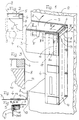
- die rechte Hälfte einer am Rand einer Gebäudeöffnung befindlichen, verformbaren Dichtung in schaubildlicher Darstellung,
- Fig. 2
- eine Teilstirnansicht der Dichtung gemäss Fig. 1, und zwar im rechten, oberen Eckbereich,
- Fig. 3
- einen Teilschnitt nach der Linie III - III von Fig. 1,
- Fig. 4
- einen Teilschnitt nach der Linie IV - IV von Fig. 1 und
- Fig. 5
- einen Teilschnitt nach der Linie V - V von Fig. 1.
- Fig. 1
- the right half of a deformable seal located at the edge of a building opening in a diagrammatic representation,
- Fig. 2
- 2, a partial front view of the seal according to FIG. 1, in the upper right corner area,
- Fig. 3
- 2 shows a partial section along the line III-III of FIG. 1,
- Fig. 4
- a partial section along the line IV - IV of Fig. 1 and
- Fig. 5
- a partial section along the line V - V of Fig. 1st
Die Gebäudeöffnung 1 des Gebäudes mit Wandung 2 kann durch ein Sektionaltor verschlossen werden; vor der Gebeäudeöffnung 1 befindet sich die erfindungsgemässe verformbare Dichtung.The building opening 1 of the building with
Diese Dichtung soll den Spalt zwischen einem andockenden Fahrzeug und dem Rand der Gebäudeöffnung 1 abdichten. Im Abstand von der Wandung 2 ist daher eine verformbare Schürze aus einem oben gelegenen Querteil 3 und einem zu beiden Seiten der Gebäudeöffnung 1 befindlichen senkrechten Streifen 4 vorgesehen. Diese Elemente 3, 4 bestehen aus einem verformbaren, reissfesten Material z.B. einem gummierten Gewebe. Diese Schürze soll sich der Gestalt des Fahrzeuges anpasssen können.This seal is intended to seal the gap between a docking vehicle and the edge of the building opening 1. At a distance from the
Das Querteil 3 ist gardinenartig am oberen Rand an einem Querträger 5 mit daran befestigter Profilschiene 5' aufgehängt. Von dem Querträger 5 aus erstreckt sich eine Dachplane 7 nach hinten, die an der Wandung 2 verankert ist. Die Enden des Querträgers 5 liegen lose auf dem freien Ende eines an der Wandung gelagerten, waagerechten Armes 6 auf. Der Querträger 5 ist zudem durch sich nach hinten erstreckende Lenker - nicht dargestellt - im Sinne des Pfeiles a verschwenkbar, um so die Dachplane 7, den Querträger 5 und das Querteil 3 nach oben bewegen zu können, wenn dies z.B. für das Andocken von Sattelschleppern erforderlich wird.The
Die an ihrem oberen Ende hinter dem Querteil 3 befindlichen Streifen 4 sind am freien Ende von Tragkörpern lo befestigt, die eine seitlich aussen gelegene Bespannung 11 aufweisen, um den Raum zwischen der Wandung 2 und den Streifen 4 zu überbrücken bzw. abzudichten. Die Tragkörper lo sind zudem elastisch nachgiebig, also in Richtung auf das Gebäude verformbar. Sie werden von Schaumstoffblöcken gebildet, können aber auch andere Tragelemente aufweisen.The
Um den Spalt zwischen der Bespannung 11 und der Dachplane 7 abzudichten, ist diese mit einer einen Überhang 8 bildenden Verlängerung versehen, die das obere Ende der Tragkörper 1o bzw. der Bespannung 11 überdeckt und frei herabhängt. Zudem ist der vordere Rand 13 des Überhangs 8 mit dem seitlich aussen gelegenen Rand des Querteils 3 wasserdicht verbunden, was durch Verkleben od. dgl. bzw. durch Hinterlegen eines Streifens 12 herbeigeführt werden kann. Damit kann die Verlängerung 8 z.B. bei Windeinwirkung nicht abheben, und es ist auch dann im oberen Eckbereich ein Abdichtung sichergestellt, wenn die Dachplane 7 mit den hiermit verbundenen Teilen nach oben verschwenkt werden sollte.In order to seal the gap between the covering 11 and the
Wie aus Fig. 5 erkennbar ist, erfolgt die Befestigung des vorderen Endes der Dachplane 7 durch Einführen in eine hinterschnittene Nut 14 der Profilschiene 5', während das obere, verdickte Ende des Querteils 3 in eine andere Längsnut 15 mit Hinterschneidung eingeführt wird. Um unter diesen Voraussetzungen die Montage zu vereinfachen, ist das Querteil 3 an seinen beiden Enden geteilt. Es ist ein mit der Verlängerung 8 verbundener Endabschnitt 3o vorgesehen, der nach der Montage des Mittelteils leicht in das Ende der Profilschiene 5' eingeführt werden kann. Um den senkrechten Stumpfstoss 16 abzudichten, ist der Endabschnitt 3o mit einer Lasche 17 versehen, der den Spalt überbrückt, wobei es sich versteht, dass alle Teile biegsam und verformbar sind. Vorzugsweise wird der Stumpfstoss 16 bzw. die Breite des Endabschnittes 3o so gewählt, dass sich der Stumpfstoff 16 noch vor den Streifen 4 befindet.As can be seen from FIG. 5, the front end of the
Es sei erwähnt, dass das Querteil 3, insb. aber die beiden Endabschnitte 3o zweckmässigerweise durch kleine Schrauben od. dgl. an der Profilschiene 5' fixiert werden, um ein ungewolltes Herausrutschen zu verhindern.It should be mentioned that the
Erwähnt sei ferner, dass die Länge der den Überhang 8 bildenden Verlängerung beliebig gewählt und auf die gewünschte Hubbewegung der Dachplane 7 abgestimmt werden kann.It should also be mentioned that the length of the extension forming the
Claims (8)
- Deformable seal for sealing the gap between the edge of a building opening (1) and the rear of a vehicle which has been driven up to said opening, having a soft, deformable apron formed from two vertical strips (4), which are situated on both sides of the building opening (1), and one transverse member (3), which is situated in the region of the upper strip ends and is situated in front of these ends, said transverse member being suspended from a cross-piece member (5), from which a top cover (7) extends towards the building, the two vertical strips (4) being mounted on the front of a supporting body (10) provided with a lateral covering (11) as the means for connecting the lateral edges of the vertical strips (4) to the building, the supporting body (10) being deformable in an elastically resilient manner in a direction towards the building independently of the top cover (7) and the transverse member (3), and, moreover, the top cover (7) being provided at both ends with a freely downwardly hanging curtain (8), which covers the upper end of the supporting body (10), or respectively of the covering (11), characterised in that the front edges (13) of the curtains (8) remote from the building (2) are securely connected to the lateral external edges of the transverse member (3).
- Seal according to claim 1, characterised in that the edges (13) are connected by gluing or the like and are possibly connected by placing a strip (12) therebehind.
- Seal according to claim 1, characterised in that the end portions (30) of the transverse member (3) facing the curtain (8) are separated from the remaining portion of the transverse member (3), and in that the end portions (30) and the remaining portion are disposed close up to one another on the cross-piece member (5) so as to form a joint (16) which is preferably vertical.
- Seal according to claim 3, characterised in that a cover plate (17) is mounted on the rear surface of the end portions (30) and covers the joint (16).
- Seal according to claim 3, characterised in that the joint (16) is situated in the region of the vertical strips (4) or respectively in front of these strips.
- Seal according to claim 3, characterised in that the end portions (30) are prevented from slipping out of their mounting profiles (5').
- Seal according to one or more of the preceding claims, having a raisable top cover (7) and an appropriately displaceable transverse member (3).
- Seal according to one or more of the preceding claims, wherein the supporting bodies (10), or respectively their supporting elements, are blocks formed from soft-set elastomeric foam.
Applications Claiming Priority (2)
| Application Number | Priority Date | Filing Date | Title |
|---|---|---|---|
| DE4210298A DE4210298C1 (en) | 1992-03-28 | 1992-03-28 | |
| DE4210298 | 1992-03-28 |
Publications (3)
| Publication Number | Publication Date |
|---|---|
| EP0563648A2 EP0563648A2 (en) | 1993-10-06 |
| EP0563648A3 EP0563648A3 (en) | 1994-01-12 |
| EP0563648B1 true EP0563648B1 (en) | 1996-07-10 |
Family
ID=6455364
Family Applications (1)
| Application Number | Title | Priority Date | Filing Date |
|---|---|---|---|
| EP93104030A Expired - Lifetime EP0563648B1 (en) | 1992-03-28 | 1993-03-12 | Flexible sealing of the gap between the edge of an opening in a building and the rear of a vehicle drawn up to the same |
Country Status (3)
| Country | Link |
|---|---|
| EP (1) | EP0563648B1 (en) |
| AT (1) | ATE140300T1 (en) |
| DE (2) | DE4210298C1 (en) |
Families Citing this family (1)
| Publication number | Priority date | Publication date | Assignee | Title |
|---|---|---|---|---|
| DE9313143U1 (en) * | 1993-09-01 | 1993-10-28 | Alten K | Sealing the gap between the edge of a building opening and the rear of a docking vehicle |
Family Cites Families (2)
| Publication number | Priority date | Publication date | Assignee | Title |
|---|---|---|---|---|
| US4349992A (en) * | 1980-04-11 | 1982-09-21 | Layne Richard C | Bumper seal |
| DE4111367A1 (en) * | 1990-09-25 | 1992-03-26 | Alten K | DEFORMABLE GASKET OF THE GAP BETWEEN THE EDGE OF A BUILDING OPENING AND THE REAR OF A VEHICLE APPROACHED TO THIS |
-
1992
- 1992-03-28 DE DE4210298A patent/DE4210298C1/de not_active Expired - Fee Related
-
1993
- 1993-03-12 EP EP93104030A patent/EP0563648B1/en not_active Expired - Lifetime
- 1993-03-12 AT AT93104030T patent/ATE140300T1/en not_active IP Right Cessation
- 1993-03-12 DE DE59303170T patent/DE59303170D1/en not_active Expired - Fee Related
Also Published As
| Publication number | Publication date |
|---|---|
| EP0563648A3 (en) | 1994-01-12 |
| DE4210298C1 (en) | 1993-08-05 |
| DE59303170D1 (en) | 1996-08-14 |
| EP0563648A2 (en) | 1993-10-06 |
| ATE140300T1 (en) | 1996-07-15 |
Similar Documents
| Publication | Publication Date | Title |
|---|---|---|
| EP0083696B1 (en) | Vertically movable window pane, especially for motor cars | |
| EP0163187B1 (en) | Vehicle roof luggage carrier | |
| EP0477674B1 (en) | Flexible sealing of the gap between the edge of an opening in a building and the rear of a vehicle drawn up to the same | |
| EP0477695B1 (en) | Flexible sealing of the gap between the edge of an opening in a building and the tail of a vehicle drawn up to the same | |
| DE10038200B4 (en) | Window seal for attachment to a motor vehicle door | |
| EP0121821B1 (en) | Window assembly with vertically slidable panes, especially for motor vehicles | |
| EP0563648B1 (en) | Flexible sealing of the gap between the edge of an opening in a building and the rear of a vehicle drawn up to the same | |
| EP0477675B1 (en) | Flexible sealing of the gap between the edge of an opening in a building and the tail of a vehicle drawn up to the same | |
| AT398107B (en) | POOL ROOFING | |
| DE3432277C2 (en) | Deformable seal of the gap between the edge of a building opening and the rear of a vehicle | |
| DE3912897A1 (en) | Corner unit for a window-pane guiding channel | |
| EP0641731B1 (en) | Sealing of the gap between the edge of an aperture in a building and the rear of a vehicle | |
| EP0641732B1 (en) | Sealing of the gap between the edge of an aperture in a building and the rear of a vehicle | |
| EP0186093A1 (en) | Compressible seal at the lower edge of a dock seal | |
| DE19606219C1 (en) | Deforming seal for gap between rear of vehicle and opening in building | |
| DE4242088A1 (en) | Deformable seal of the gap between the edge of a building opening and the rear of a vehicle approaching it | |
| DE4326872C2 (en) | Sealing the gap between the edge of a building opening and the rear of a docking vehicle | |
| DE2551917C3 (en) | Rigid awning roof for caravans | |
| DE4023823A1 (en) | Attachment of rain channel to car roof - makes use of plastics push fit fasteners | |
| EP0758710B1 (en) | Device for the weather proof bridging of the gap between the rear of a vehicle and the border of a wall opening | |
| DE7538523U (en) | CONNECTOR FOR SEALING THE LOWER EDGE OF A ROOF WINDOW | |
| DE2222520C3 (en) | Metal casement window | |
| DE10205960B4 (en) | Cover for a roof opening of a motor vehicle | |
| DE3222942A1 (en) | Seal arrangement, in particular for doors of motor vehicles | |
| DE20221112U1 (en) | Glass door without a threshold, and a seal which can be lowered, has an adhesive bond between the upper laying surface of the seal and the bottom surface of the door panel, with a narrow sealing surface |
Legal Events
| Date | Code | Title | Description |
|---|---|---|---|
| PUAI | Public reference made under article 153(3) epc to a published international application that has entered the european phase |
Free format text: ORIGINAL CODE: 0009012 |
|
| AK | Designated contracting states |
Kind code of ref document: A2 Designated state(s): AT BE CH DE DK ES FR GB IE IT LI NL PT SE |
|
| PUAL | Search report despatched |
Free format text: ORIGINAL CODE: 0009013 |
|
| AK | Designated contracting states |
Kind code of ref document: A3 Designated state(s): AT BE CH DE DK ES FR GB IE IT LI NL PT SE |
|
| 17P | Request for examination filed |
Effective date: 19940316 |
|
| GRAG | Despatch of communication of intention to grant |
Free format text: ORIGINAL CODE: EPIDOS AGRA |
|
| GRAH | Despatch of communication of intention to grant a patent |
Free format text: ORIGINAL CODE: EPIDOS IGRA |
|
| 17Q | First examination report despatched |
Effective date: 19951218 |
|
| GRAH | Despatch of communication of intention to grant a patent |
Free format text: ORIGINAL CODE: EPIDOS IGRA |
|
| GRAA | (expected) grant |
Free format text: ORIGINAL CODE: 0009210 |
|
| AK | Designated contracting states |
Kind code of ref document: B1 Designated state(s): AT BE CH DE DK ES FR GB IE IT LI NL PT SE |
|
| PG25 | Lapsed in a contracting state [announced via postgrant information from national office to epo] |
Ref country code: NL Free format text: LAPSE BECAUSE OF FAILURE TO SUBMIT A TRANSLATION OF THE DESCRIPTION OR TO PAY THE FEE WITHIN THE PRESCRIBED TIME-LIMIT Effective date: 19960710 Ref country code: IT Free format text: LAPSE BECAUSE OF FAILURE TO SUBMIT A TRANSLATION OF THE DESCRIPTION OR TO PAY THE FEE WITHIN THE PRE;WARNING: LAPSES OF ITALIAN PATENTS WITH EFFECTIVE DATE BEFORE 2007 MAY HAVE OCCURRED AT ANY TIME BEFORE 2007. THE CORRECT EFFECTIVE DATE MAY BE DIFFERENT FROM THE ONE RECORDED.SCRIBED TIME-LIMIT Effective date: 19960710 Ref country code: GB Effective date: 19960710 Ref country code: FR Effective date: 19960710 Ref country code: ES Free format text: THE PATENT HAS BEEN ANNULLED BY A DECISION OF A NATIONAL AUTHORITY Effective date: 19960710 Ref country code: DK Effective date: 19960710 |
|
| REF | Corresponds to: |
Ref document number: 140300 Country of ref document: AT Date of ref document: 19960715 Kind code of ref document: T |
|
| REG | Reference to a national code |
Ref country code: IE Ref legal event code: FG4D Free format text: 69077 |
|
| REF | Corresponds to: |
Ref document number: 59303170 Country of ref document: DE Date of ref document: 19960814 |
|
| PG25 | Lapsed in a contracting state [announced via postgrant information from national office to epo] |
Ref country code: SE Effective date: 19961010 Ref country code: PT Effective date: 19961010 |
|
| NLV1 | Nl: lapsed or annulled due to failure to fulfill the requirements of art. 29p and 29m of the patents act | ||
| EN | Fr: translation not filed | ||
| GBV | Gb: ep patent (uk) treated as always having been void in accordance with gb section 77(7)/1977 [no translation filed] |
Effective date: 19960710 |
|
| PG25 | Lapsed in a contracting state [announced via postgrant information from national office to epo] |
Ref country code: IE Free format text: LAPSE BECAUSE OF NON-PAYMENT OF DUE FEES Effective date: 19970306 |
|
| PG25 | Lapsed in a contracting state [announced via postgrant information from national office to epo] |
Ref country code: AT Free format text: LAPSE BECAUSE OF NON-PAYMENT OF DUE FEES Effective date: 19970312 |
|
| REG | Reference to a national code |
Ref country code: IE Ref legal event code: FD4D Ref document number: 69077 Country of ref document: IE |
|
| PG25 | Lapsed in a contracting state [announced via postgrant information from national office to epo] |
Ref country code: LI Effective date: 19970331 Ref country code: CH Effective date: 19970331 Ref country code: BE Effective date: 19970331 |
|
| PLBE | No opposition filed within time limit |
Free format text: ORIGINAL CODE: 0009261 |
|
| STAA | Information on the status of an ep patent application or granted ep patent |
Free format text: STATUS: NO OPPOSITION FILED WITHIN TIME LIMIT |
|
| 26N | No opposition filed | ||
| REG | Reference to a national code |
Ref country code: CH Ref legal event code: PL |
|
| REG | Reference to a national code |
Ref country code: FR Ref legal event code: TP |
|
| PGFP | Annual fee paid to national office [announced via postgrant information from national office to epo] |
Ref country code: DE Payment date: 20030530 Year of fee payment: 11 |
|
| PG25 | Lapsed in a contracting state [announced via postgrant information from national office to epo] |
Ref country code: DE Free format text: LAPSE BECAUSE OF NON-PAYMENT OF DUE FEES Effective date: 20041001 |