EP0563549B1 - A medical suturing device, and die mechanism forming it - Google Patents
A medical suturing device, and die mechanism forming it Download PDFInfo
- Publication number
- EP0563549B1 EP0563549B1 EP93102106A EP93102106A EP0563549B1 EP 0563549 B1 EP0563549 B1 EP 0563549B1 EP 93102106 A EP93102106 A EP 93102106A EP 93102106 A EP93102106 A EP 93102106A EP 0563549 B1 EP0563549 B1 EP 0563549B1
- Authority
- EP
- European Patent Office
- Prior art keywords
- suture
- crimping dies
- crimping
- drive ring
- needle
- Prior art date
- Legal status (The legal status is an assumption and is not a legal conclusion. Google has not performed a legal analysis and makes no representation as to the accuracy of the status listed.)
- Expired - Lifetime
Links
- 238000002788 crimping Methods 0.000 claims abstract description 69
- 239000000463 material Substances 0.000 claims description 4
- 230000001105 regulatory effect Effects 0.000 claims description 3
- 230000001276 controlling effect Effects 0.000 claims 1
- 238000000034 method Methods 0.000 abstract description 16
- 238000007373 indentation Methods 0.000 description 7
- 238000007796 conventional method Methods 0.000 description 3
- 238000004519 manufacturing process Methods 0.000 description 3
- 238000012360 testing method Methods 0.000 description 3
- 230000000295 complement effect Effects 0.000 description 1
- 238000010348 incorporation Methods 0.000 description 1
- 238000003780 insertion Methods 0.000 description 1
- 230000037431 insertion Effects 0.000 description 1
- 210000000056 organ Anatomy 0.000 description 1
- 229910001220 stainless steel Inorganic materials 0.000 description 1
- 239000010935 stainless steel Substances 0.000 description 1
- 229920002994 synthetic fiber Polymers 0.000 description 1
Images




Classifications
-
- A—HUMAN NECESSITIES
- A61—MEDICAL OR VETERINARY SCIENCE; HYGIENE
- A61B—DIAGNOSIS; SURGERY; IDENTIFICATION
- A61B17/00—Surgical instruments, devices or methods
- A61B17/04—Surgical instruments, devices or methods for suturing wounds; Holders or packages for needles or suture materials
- A61B17/0485—Devices or means, e.g. loops, for capturing the suture thread and threading it through an opening of a suturing instrument or needle eyelet
-
- B—PERFORMING OPERATIONS; TRANSPORTING
- B21—MECHANICAL METAL-WORKING WITHOUT ESSENTIALLY REMOVING MATERIAL; PUNCHING METAL
- B21K—MAKING FORGED OR PRESSED METAL PRODUCTS, e.g. HORSE-SHOES, RIVETS, BOLTS OR WHEELS
- B21K21/00—Making hollow articles not covered by a single preceding sub-group
- B21K21/12—Shaping end portions of hollow articles
-
- A—HUMAN NECESSITIES
- A61—MEDICAL OR VETERINARY SCIENCE; HYGIENE
- A61B—DIAGNOSIS; SURGERY; IDENTIFICATION
- A61B17/00—Surgical instruments, devices or methods
- A61B17/04—Surgical instruments, devices or methods for suturing wounds; Holders or packages for needles or suture materials
- A61B17/0483—Hand-held instruments for holding sutures
-
- A—HUMAN NECESSITIES
- A61—MEDICAL OR VETERINARY SCIENCE; HYGIENE
- A61B—DIAGNOSIS; SURGERY; IDENTIFICATION
- A61B17/00—Surgical instruments, devices or methods
- A61B17/04—Surgical instruments, devices or methods for suturing wounds; Holders or packages for needles or suture materials
- A61B17/0491—Sewing machines for surgery
-
- A—HUMAN NECESSITIES
- A61—MEDICAL OR VETERINARY SCIENCE; HYGIENE
- A61B—DIAGNOSIS; SURGERY; IDENTIFICATION
- A61B17/00—Surgical instruments, devices or methods
- A61B17/04—Surgical instruments, devices or methods for suturing wounds; Holders or packages for needles or suture materials
- A61B17/06—Needles ; Sutures; Needle-suture combinations; Holders or packages for needles or suture materials
- A61B17/06004—Means for attaching suture to needle
-
- B—PERFORMING OPERATIONS; TRANSPORTING
- B21—MECHANICAL METAL-WORKING WITHOUT ESSENTIALLY REMOVING MATERIAL; PUNCHING METAL
- B21F—WORKING OR PROCESSING OF METAL WIRE
- B21F15/00—Connecting wire to wire or other metallic material or objects; Connecting parts by means of wire
-
- B—PERFORMING OPERATIONS; TRANSPORTING
- B21—MECHANICAL METAL-WORKING WITHOUT ESSENTIALLY REMOVING MATERIAL; PUNCHING METAL
- B21J—FORGING; HAMMERING; PRESSING METAL; RIVETING; FORGE FURNACES
- B21J7/00—Hammers; Forging machines with hammers or die jaws acting by impact
- B21J7/02—Special design or construction
- B21J7/14—Forging machines working with several hammers
- B21J7/145—Forging machines working with several hammers the hammers being driven by a rotating annular driving member
-
- A—HUMAN NECESSITIES
- A61—MEDICAL OR VETERINARY SCIENCE; HYGIENE
- A61B—DIAGNOSIS; SURGERY; IDENTIFICATION
- A61B17/00—Surgical instruments, devices or methods
- A61B17/04—Surgical instruments, devices or methods for suturing wounds; Holders or packages for needles or suture materials
- A61B17/06—Needles ; Sutures; Needle-suture combinations; Holders or packages for needles or suture materials
- A61B17/06066—Needles, e.g. needle tip configurations
-
- A—HUMAN NECESSITIES
- A61—MEDICAL OR VETERINARY SCIENCE; HYGIENE
- A61B—DIAGNOSIS; SURGERY; IDENTIFICATION
- A61B17/00—Surgical instruments, devices or methods
- A61B17/04—Surgical instruments, devices or methods for suturing wounds; Holders or packages for needles or suture materials
- A61B17/06—Needles ; Sutures; Needle-suture combinations; Holders or packages for needles or suture materials
- A61B17/06004—Means for attaching suture to needle
- A61B2017/06028—Means for attaching suture to needle by means of a cylindrical longitudinal blind bore machined at the suture-receiving end of the needle, e.g. opposite to needle tip
-
- Y—GENERAL TAGGING OF NEW TECHNOLOGICAL DEVELOPMENTS; GENERAL TAGGING OF CROSS-SECTIONAL TECHNOLOGIES SPANNING OVER SEVERAL SECTIONS OF THE IPC; TECHNICAL SUBJECTS COVERED BY FORMER USPC CROSS-REFERENCE ART COLLECTIONS [XRACs] AND DIGESTS
- Y10—TECHNICAL SUBJECTS COVERED BY FORMER USPC
- Y10T—TECHNICAL SUBJECTS COVERED BY FORMER US CLASSIFICATION
- Y10T29/00—Metal working
- Y10T29/49—Method of mechanical manufacture
- Y10T29/49826—Assembling or joining
- Y10T29/49908—Joining by deforming
-
- Y—GENERAL TAGGING OF NEW TECHNOLOGICAL DEVELOPMENTS; GENERAL TAGGING OF CROSS-SECTIONAL TECHNOLOGIES SPANNING OVER SEVERAL SECTIONS OF THE IPC; TECHNICAL SUBJECTS COVERED BY FORMER USPC CROSS-REFERENCE ART COLLECTIONS [XRACs] AND DIGESTS
- Y10—TECHNICAL SUBJECTS COVERED BY FORMER USPC
- Y10T—TECHNICAL SUBJECTS COVERED BY FORMER US CLASSIFICATION
- Y10T29/00—Metal working
- Y10T29/49—Method of mechanical manufacture
- Y10T29/49826—Assembling or joining
- Y10T29/49908—Joining by deforming
- Y10T29/49925—Inward deformation of aperture or hollow body wall
Definitions
- the present invention relates to single-strike die to produce a medical suturing device. More particularly, the present invention relates to a single-strike die to attach a surgical suture to a surgical needle.
- the needle punctures the tissue from the outside on one side of the wound, traverses across the wound and then punctures the tissue from the inside on the other side of the wound, pulling the suture through these punctured openings.
- the suture is then tied-off to form a single suture, or stitch, and to close the wound between the punctured openings. This procedure is repeated along the length of the wound.
- the needle is usually curved to make it easier to push through both sides of the tissue and includes a sharpened tip at its lead or distal end and a hollow barrel at its trailing or proximal end, which is hollow by virtue of being formed with a blind axial hole.
- the suture is axially inserted into the hollow end and secured in the barrel. It is important to tightly secure the suture within the barrel so it does not loosen and become separated from the needle during the hand-suturing procedure.
- Another conventional method for attaching a surgical suture to the hollow barrel of a surgical needle involves the use of a single-strike die.
- the die is so named because it crimps the barrel of the needle in a plurality of locations in a single crimping procedure.
- Canadian Patent No. 1,022,734 shows such a single-strike die for securing a suture to a surgical needle.
- Two dies are used to perform the crimping, or swaging, procedure.
- each die is machined to have a die profile with two flat faces formed at a 90° angle to one another thereby to define a V-shaped notch. As the dies are compressed about the suture-containing needle barrel, the needle is crimped at four radial locations about the barrel.
- Another example shows one die with a flat face and a second die with a V-shaped opening that together crimp the suture-containing needle at three locations about the barrel.
- the multi-faceted profiles of these dies are expensive to machine.
- these die profiles are machined to fit specific barrel diameters. Therefore, the dies must be changed if needles with barrels of a different diameter are to be crimped.
- a medical suturing device comprises a surgical needle having a pointed leading end and a trailing barrel end, with a surgical suture axially inserted in the barrel end.
- the barrel end is compressed about its circumference at a plurality, for example, three, symmetrical locations to provide indentations for securing the suture therein.
- a single-strike die mechanism for securing a surgical suture to a barrel of a surgical needle comprises a cam drive ring, having a radial opening, mounted for rotational movement about a central axis, cam drive ring mounting means for rotationally mounting the cam drive ring, and drive means for rotating the cam drive ring.
- a plurality of crimping dies are mounted for movement in a radial direction with respect to the central axis, and a die guide symmetrically mounts each of the plurality of crimping dies for linear movement in the radial direction.
- actuating means linearly actuate the plurality of crimping dies in the radial direction.
- a method of producing a medical suturing device by use of a single-strike die having a plurality of crimping dies comprises the steps of positioning the crimping dies generally to form a circumscribed circle larger in diameter than the barrel end of a surgical needle, inserting the needle within the circumscribed circle, and closing the crimping dies to a gripping position for lightly gripping the barrel to secure the needle but so as not to deform the barrel.
- a surgical suture is then axially inserted into the barrel and the crimping dies are further closed simultaneously to apply a crimping force to deform the barrel.
- the crimping dies are opened slightly to a testing position which releases the crimping force but does not permit axial movement of the barrel.
- the medical suturing device is tested by applying a tensioning force to the suture, and if the device is satisfactory, the crimping dies are then further opened to release the medical suturing device.
- FIGS 1 through 3 illustrate a medical suturing device 10 in accordance with the present invention.
- the suturing device comprises a surgical needle 12 curved in a conventional manner and having a pointed forward or distal end 14 for piercing the tissue and a trailing, proximal hollow barrel end 16 formed by having a blind axial hole therein.
- a surgical suture 20 is axially inserted into the hollow barrel end to complete the device 10.
- the needle can be made, for example, of surgical grade stainless steel, and the suture can be made of either natural or synthetic material and consist of a monofilament or a multifilament braided structure as are known in the art.
- Figures 2 and 3 show the hollow barrel end of the needle 12 and illustrate how the suture 20 is secured therein.
- the wall of the hollow barrel end is deformed to form three radial indentations 18 that may be arcuate or convex as shown in detail Figure 3, thereby being partially cylindrical having a radius greater than the radius of the major portion of the needle.
- the indentations may be substantial flat as described in greater detail below.
- Deforming the barrel wall reduces the internal diameter of the barrel and compresses, or squeezes, the suture so it is secured within the needle.
- the radial indentations are symmetrically spaced around the periphery of the barrel as shown in Figure 3.
- Each indentation 18 is compressed toward a centerline 17 in the barrel 16 with the same force to apply three substantially equal forces to the suture through the barrel wall symmetrically about its circumference. It has been found that by using at least three symmetrically applied forces, the suture can be securely attached to the needle and will not become separated therefrom during the hand-suturing procedure.
- the apparatus and method for deforming the barrel of the needle 12 to secure the suture 20 therein are discussed below with reference to Figures 4 to 10.
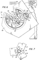
- a single-strike die mechanism 30, in accordance with a first embodiment of the present invention, for assembling the medical suturing device also in accordance with the present invention is best seen in Figures 4 and 6.
- the single-strike die mechanism 30 has a set of three crimping dies 32 supported for linear movement in a die guide 34.
- the crimping dies slide in a radial direction within symmetrically disposed paths 36 in the die guide, with each path having a wide-end portion 38 for reasons discussed below.
- the die guide 34 is substantially circular in shape, with the symmetrically disposed paths 36 being equally spaced 120° from each other and extending radially outwardly from a center axis 31 of the single-strike die.
- Leaf springs 33 are secured in the die guide and each urges one crimping die 32 radially outwardly from the center axis.
- Each crimping die is actuated through its association with a roller bearing 40 and a cooperating cam 42.
- Each roller bearing 40 is confined within the wide-end portion 38 of one path 36 between an angled camming surface 44 of one cam 42 and the opposed end of a crimping die 32.
- the cams are positioned about the inner circumference of a cam drive ring 46, which in turn is supported for rotational movement within a drive ring housing 48.
- Ball or roller bearings 50 are positioned between the cam drive ring 46 and the drive ring housing 48 to provide smooth and precise rotational movement of the cam drive ring.
- a drive gear 51 rotates the cam drive ring through the meshing of its gear teeth 53 and a sector of gear teeth 47 on the drive ring 46.
- the drive gear 51 is connected to a drive shaft 54 which is driven by a motor (not shown).
- each crimping die has a deforming face 35.
- Each deforming face 35 has a recessed arcuate or concave crimping surface 37 and laterally angled surfaces 39 at its leading end.
- the crimping faces in this embodiment desirably have a radius larger than that of the needle.
- the die guide and cam drive ring define a radial opening 49 that leads from the center axis 31 of the single-strike die to the outside of the drive ring housing.
- the mechanism 30 can be positioned so that the assembled suturing device may be removed through this radial opening 49 at the completion of an operating cycle of the single-strike die.
- a preferred embodiment of the invention includes a computer controlled operating system 56 and a sensor 58, as shown diagrammatically in Figures 4 and 6, to operate the single-strike die.
- the sensor 58 is used to sense the pressure with which a needle is gripped or deformed by the crimping dies and produces an output signal to which the computer controlled operating system 56 responds.
- the system 56 can be programmed to operate the mechanism 30 through its cycle described below based on such parameters as the diameter and material of the needle, the wall thickness of the hollow barrel end, the material and structure of the suture thread, and the lubricity of the surface of the suture inserted into the hollow barrel end.
- an additional sensor (not shown) can be adapted to sense the removal of a completed suturing device from the die mechanism to initiate a subsequent operating cycle.
- the production process starts with the crimping dies in an open position.
- the crimping dies are shown in Figure 4 to be in that open position.
- the cam drive ring 46 is then rotated in the clockwise direction by the drive gear 51 to drive the crimping dies in radially inward directions to a needle inserting position.
- the surfaces 37 of the crimping dies generally circumscribe or define a circle of slightly larger diameter than the surgical needle. The surgical needle without the suture may then be guided to the location within the circumscribed circle.
- the crimping dies 32 are thereafter again driven in the radially inward directions to a needle hold/suture insertion position.
- the barrel end of the needle is gripped firmly to precisely align its centerline 17 with the central axis 31 of the single-strike die mechanism.
- the computer controlled operating system 56 for example, which may respond to sensing by the sensor 58 of the gripping of the needle by the crimping dies, or which may be programmed directly to do so, the needle is gripped lightly enough so as not to deform the barrel. The surgical suture is then axially inserted into the barrel while the needle is held in this position.
- the crimping dies 32 are then driven further in the radially inward directions to deform the barrel and securely crimp the needle around the suture.
- the barrel 16 is simultaneously compressed by crimping dies 32 at three symmetrical positions to crimp the suture within the barrel.
- the direction of rotating the cam drive ring is reversed by reversing drive of the drive gear 51 and the crimping dies are then permitted to be urged in the radially outward directions by the force of the leaf springs 33.
- the crimping dies are first permitted to withdraw only slightly from the indentations formed in the barrel to a testing position.
- the circle generally circumscribed by the crimping dies in the testing position is smaller than the undeformed diameter of the barrel. Therefore, axial movement of the needle is prevented. In this position, a tensioning force is applied to the suture to attempt to remove it from the needle. This tensioning force is measured against a predetermined force value. If the suture remains crimped in the needle when the predetermined tensioning force is applied to the suture, it is judged that the suture is satisfactorily attached within the needle.
- the crimping dies are permitted to be urged further in the radially outward directions by the leaf springs by further counterclockwise rotation of the cam drive ring 46 again to be placed in the open position.
- the crimping dies thus completely release the suturing device in this position, and it may be removed from the single-strike die mechanism through the radial opening 49.
- the configuration of the single-strike die mechanism in accordance with the present invention produces a needle-suture assembly quickly and efficiently, and in which the suture and needle are reliably secured together.
- the computer control of the single-strike die mechanism in accordance with the present invention enables the positions of the crimping dies to be controlled accurately to within tenths of thousandths of an inch.
- the single-strike die mechanism can continually and consistently produce reliable medical suturing devices.
- the computer controlled operating system is operated by software, adjusting the single-strike die to accommodate needles of different diameters can be done almost instantaneously by regulating the positions of the crimping dies. This feature significantly reduces the amount of retooling of the crimping dies that must be done to accommodate needles of different diameters.
- FIG. 8 A second embodiment of the single-strike die mechanism of the present invention is shown in Figures 8, 9 and 10.
- the components of this mechanism are identical to those of the first embodiments shown in Figures 5, 6 and 7 and as described above, with one-exception. Therefore, all reference numerals used in Figures 8, 9 and 10 are the same as those used in Figures 5, 6 and 7 but with the addition of a "prime".
- the difference between the first and second embodiments is that in the second the crimping surface 37' on each deforming face 35' of each die 32' is flat, not concave. Therefore the second embodiment will produce three substantially flat, not convex, indentations in the hollow barrel end of the needle when it is crimped by the die mechanism.
- the convex surfaces 18 shown in Figures 2 and 3 will appear substantially flat as shown in Figures 9 and 10 when produced by the die mechanism of the second embodiment.
- This second configuration may be desirable when added crimping force is sought to be applied to the suture.
Landscapes
- Health & Medical Sciences (AREA)
- Engineering & Computer Science (AREA)
- Surgery (AREA)
- Life Sciences & Earth Sciences (AREA)
- Mechanical Engineering (AREA)
- Molecular Biology (AREA)
- Veterinary Medicine (AREA)
- Medical Informatics (AREA)
- Biomedical Technology (AREA)
- Animal Behavior & Ethology (AREA)
- General Health & Medical Sciences (AREA)
- Public Health (AREA)
- Heart & Thoracic Surgery (AREA)
- Nuclear Medicine, Radiotherapy & Molecular Imaging (AREA)
- Surgical Instruments (AREA)
- Electrotherapy Devices (AREA)
- Materials For Medical Uses (AREA)
- Perforating, Stamping-Out Or Severing By Means Other Than Cutting (AREA)
- Forging (AREA)
Abstract
Description
Claims (8)
- A single-strike die mechanism for securing a surgical suture in the hollow barrel end (16) of a surgical needle (12), said mechanism (30) comprisinga plurality of crimping dies (32);a die guide (34) for mounting said crimping dies (32) for linear movement in a radial direction with respect to a central axis (31), said crimping dies being mounted in said die guide (34) symmetrically about the central axis (31);drive means for simultaneously linearly driving said crimping dies (32) in the radial direction to crimp therebetween the hollow barrel end (16) of a surgical needle (12), with the suture received therein;
characterized in thatsaid drive means comprises:a cam drive ring (46), having a radial opening, therein:a cam drive ring mounting means (48) for mounting said cam drive ring (46) for rotation about a central axis (31);means for rotating said cam drive ring (46); andmeans (40) linking said cam drive ring (46) and each of said plurality of crimping dies (32) for driving said crimping dies (32) in the radial direction when said cam drive ring (46) is rotated in one direction by said drive means (48). - A single-strike die mechanism (30) according to Claim 1, wherein said linking means includes cam means for converting rotational movement of said cam drive ring (46) into linear movement of said plurality of crimping dies (32).
- A single-strike die mechanism according to Claim 2, wherein said cam means includes a cam (42) and a roller bearing (40) associated with each said crimping die (32) wherein said cams (42) are mounted on said cam drive ring (46) and said roller bearings (40) are provided in said die guide (34), and wherein said cams (42) drive said roller bearings (40) and crimping dies (32) radially inwardly toward the central axis (31) when said cam drive ring (46) is rotated by said drive means (33).
- A single-strike die mechanism (30) according to Claim 1, further comprising control means (56) for regulating linear movement of said plurality of crimping dies (32) by controlling rotational movement of said cam drive ring (46).
- A single-strike die mechanism according to Claim 4, further comprising sensor means (58) for sensing the force applied radially to the hollow barrel end (16) of a surgical needle (12) by said crimping dies (32), said sensor means (58) being connected to said control means (56).
- A single-strike mechanism (30) according to Claim 1, further comprising computer control means (56) programmed to control rotation of said cam drive means by said drive means in dependence upon at least one of the diameter of the hollow barrel end (16) of the surgical needle in which a surgical suture (20) is secured, the wall thickness of the hollow barrel end (16), the material of the surgical needle (12), the material of the suture (20), the structure of the suture (20), and the lubricity of the surface of the suture (20) inserted into the hollow barrel end (16).
- A single-strike die mechanism (30) according to Claim 1, wherein each of said crimping dies (32) is formed with a crimping face (35) and each said crimping face (35) is one of partially cylindrical in shape and substantially flat.
- A single-strike die mechanism (30) according to Claim 1, further including urging means (33) for urging said crimping dies (32) radially outwardly from the central axis (31).
Applications Claiming Priority (2)
| Application Number | Priority Date | Filing Date | Title |
|---|---|---|---|
| US07/846,456 US5230352A (en) | 1992-03-04 | 1992-03-04 | Medical suturing device, a single-strike die mechanism, and a method of using said die mechanism for forming the medical suturing device |
| US846456 | 1997-05-01 |
Publications (3)
| Publication Number | Publication Date |
|---|---|
| EP0563549A2 EP0563549A2 (en) | 1993-10-06 |
| EP0563549A3 EP0563549A3 (en) | 1993-12-01 |
| EP0563549B1 true EP0563549B1 (en) | 1998-01-21 |
Family
ID=25297998
Family Applications (1)
| Application Number | Title | Priority Date | Filing Date |
|---|---|---|---|
| EP93102106A Expired - Lifetime EP0563549B1 (en) | 1992-03-04 | 1993-02-11 | A medical suturing device, and die mechanism forming it |
Country Status (13)
| Country | Link |
|---|---|
| US (2) | US5230352A (en) |
| EP (1) | EP0563549B1 (en) |
| JP (3) | JPH067359A (en) |
| KR (1) | KR930019187A (en) |
| AT (1) | ATE162381T1 (en) |
| AU (1) | AU673346B2 (en) |
| CA (1) | CA2090846C (en) |
| DE (1) | DE69316418T2 (en) |
| ES (1) | ES2111658T3 (en) |
| MX (1) | MX9301041A (en) |
| PL (1) | PL297925A1 (en) |
| TW (1) | TW245633B (en) |
| ZA (1) | ZA931519B (en) |
Families Citing this family (118)
| Publication number | Priority date | Publication date | Assignee | Title |
|---|---|---|---|---|
| US5350373A (en) * | 1992-10-09 | 1994-09-27 | United States Surgical Corporation | Apparatus for attaching surgical suture components |
| US5394971A (en) * | 1993-08-02 | 1995-03-07 | United States Surgical Corporation | Apparatus for attaching surgical suture components |
| US5383902A (en) * | 1993-06-02 | 1995-01-24 | United States Surgical Corporation | Surgical needle-suture attachment for controlled suture release |
| US5487216A (en) * | 1994-01-13 | 1996-01-30 | Ethicon, Inc. | Control system for an automatic needle-suture assembly and packaging machine |
| US5701664A (en) * | 1994-08-29 | 1997-12-30 | United States Surgical Corporation | Method and apparatus for needle-suture attachment |
| US5507798A (en) * | 1994-09-14 | 1996-04-16 | United States Surgical Corporation | Surgical needle-suture attachment for controlled suture release |
| US5707391A (en) * | 1995-06-07 | 1998-01-13 | United States Surgical Corporation | Apparatus and method for attaching surgical needle suture components |
| US5722991A (en) * | 1995-06-07 | 1998-03-03 | United States Surgical Corporation | Apparatus and method for attaching surgical needle suture components |
| FR2755042B1 (en) * | 1996-10-24 | 1998-12-24 | Lemforder Nacam Sa | PROCESS FOR OBTAINING SPLINES ON A TREE |
| US6769161B2 (en) | 1997-10-16 | 2004-08-03 | Scimed Life Systems, Inc. | Radial stent crimper |
| FR2774889B1 (en) * | 1998-02-18 | 2000-08-18 | Ethnor | DEVICE FOR ATTACHING A SUTURE THREAD TO A SURGICAL NEEDLE |
| US6016682A (en) * | 1998-08-11 | 2000-01-25 | Ethicon, Inc. | Swaging apparatus for surgical needles |
| AT406646B (en) * | 1998-12-07 | 2000-07-25 | Gfm Beteiligungs Und Managemen | ROUND KNOWING MACHINE |
| US6322582B1 (en) * | 1999-02-25 | 2001-11-27 | Ethicon, Inc. | Device for fixing a suture thread to a surgical needle |
| US6352547B1 (en) | 1999-09-22 | 2002-03-05 | Scimed Life Systems, Inc. | Stent crimping system |
| US6387117B1 (en) | 1999-09-22 | 2002-05-14 | Scimed Life Systems, Inc. | Stent crimping system |
| US6360577B2 (en) | 1999-09-22 | 2002-03-26 | Scimed Life Systems, Inc. | Apparatus for contracting, or crimping stents |
| US6629350B2 (en) * | 2000-06-08 | 2003-10-07 | Tom Motsenbocker | Stent crimping apparatus and method |
| JP4584489B2 (en) * | 2000-12-28 | 2010-11-24 | 幸義 村上 | End member mounting method to hollow shaft member for OA equipment |
| WO2002076700A1 (en) * | 2001-03-26 | 2002-10-03 | Machine Solutions, Inc. | Balloon folding technology |
| US9155544B2 (en) | 2002-03-20 | 2015-10-13 | P Tech, Llc | Robotic systems and methods |
| JP4921708B2 (en) * | 2002-08-16 | 2012-04-25 | マシーン ソリューションズ インコーポレイテッド | Caulking equipment |
| US7152452B2 (en) * | 2002-12-26 | 2006-12-26 | Advanced Cardiovascular Systems, Inc. | Assembly for crimping an intraluminal device and method of use |
| US7207204B2 (en) * | 2004-02-26 | 2007-04-24 | Boston Scientific Scimed, Inc. | Crimper |
| US7021114B2 (en) * | 2004-04-16 | 2006-04-04 | Boston Scientific Scimed, Inc. | Stent crimper |
| EP1768630B1 (en) * | 2004-06-16 | 2015-01-07 | Machine Solutions, Inc. | Stent crimping device |
| US7530253B2 (en) * | 2005-09-09 | 2009-05-12 | Edwards Lifesciences Corporation | Prosthetic valve crimping device |
| US8292920B2 (en) * | 2005-11-10 | 2012-10-23 | Tyco Healthcare Group Lp | Sickle needle and method |
| US8092465B2 (en) | 2006-06-09 | 2012-01-10 | Biomet Manufacturing Corp. | Patient specific knee alignment guide and associated method |
| US9345548B2 (en) | 2006-02-27 | 2016-05-24 | Biomet Manufacturing, Llc | Patient-specific pre-operative planning |
| US9173661B2 (en) | 2006-02-27 | 2015-11-03 | Biomet Manufacturing, Llc | Patient specific alignment guide with cutting surface and laser indicator |
| US9918740B2 (en) | 2006-02-27 | 2018-03-20 | Biomet Manufacturing, Llc | Backup surgical instrument system and method |
| US9289253B2 (en) | 2006-02-27 | 2016-03-22 | Biomet Manufacturing, Llc | Patient-specific shoulder guide |
| US8608748B2 (en) | 2006-02-27 | 2013-12-17 | Biomet Manufacturing, Llc | Patient specific guides |
| US7967868B2 (en) | 2007-04-17 | 2011-06-28 | Biomet Manufacturing Corp. | Patient-modified implant and associated method |
| US8864769B2 (en) | 2006-02-27 | 2014-10-21 | Biomet Manufacturing, Llc | Alignment guides with patient-specific anchoring elements |
| US20150335438A1 (en) | 2006-02-27 | 2015-11-26 | Biomet Manufacturing, Llc. | Patient-specific augments |
| US10278711B2 (en) | 2006-02-27 | 2019-05-07 | Biomet Manufacturing, Llc | Patient-specific femoral guide |
| US9907659B2 (en) | 2007-04-17 | 2018-03-06 | Biomet Manufacturing, Llc | Method and apparatus for manufacturing an implant |
| US8241293B2 (en) | 2006-02-27 | 2012-08-14 | Biomet Manufacturing Corp. | Patient specific high tibia osteotomy |
| US8377066B2 (en) | 2006-02-27 | 2013-02-19 | Biomet Manufacturing Corp. | Patient-specific elbow guides and associated methods |
| US8591516B2 (en) | 2006-02-27 | 2013-11-26 | Biomet Manufacturing, Llc | Patient-specific orthopedic instruments |
| US8608749B2 (en) | 2006-02-27 | 2013-12-17 | Biomet Manufacturing, Llc | Patient-specific acetabular guides and associated instruments |
| US8858561B2 (en) | 2006-06-09 | 2014-10-14 | Blomet Manufacturing, LLC | Patient-specific alignment guide |
| US9113971B2 (en) | 2006-02-27 | 2015-08-25 | Biomet Manufacturing, Llc | Femoral acetabular impingement guide |
| US8407067B2 (en) | 2007-04-17 | 2013-03-26 | Biomet Manufacturing Corp. | Method and apparatus for manufacturing an implant |
| US8568487B2 (en) | 2006-02-27 | 2013-10-29 | Biomet Manufacturing, Llc | Patient-specific hip joint devices |
| US9339278B2 (en) | 2006-02-27 | 2016-05-17 | Biomet Manufacturing, Llc | Patient-specific acetabular guides and associated instruments |
| US8535387B2 (en) | 2006-02-27 | 2013-09-17 | Biomet Manufacturing, Llc | Patient-specific tools and implants |
| US8603180B2 (en) | 2006-02-27 | 2013-12-10 | Biomet Manufacturing, Llc | Patient-specific acetabular alignment guides |
| US8133234B2 (en) | 2006-02-27 | 2012-03-13 | Biomet Manufacturing Corp. | Patient specific acetabular guide and method |
| US9795399B2 (en) | 2006-06-09 | 2017-10-24 | Biomet Manufacturing, Llc | Patient-specific knee alignment guide and associated method |
| GB2442441B (en) * | 2006-10-03 | 2011-11-09 | Biomet Uk Ltd | Surgical instrument |
| WO2008077254A1 (en) * | 2006-12-26 | 2008-07-03 | Socovar Societe En Commandite | Closure apparatus |
| JP5112756B2 (en) * | 2007-06-13 | 2013-01-09 | テルモ株式会社 | Blood pressure measurement device |
| JP5112767B2 (en) * | 2007-07-18 | 2013-01-09 | テルモ株式会社 | Blood pressure measurement device |
| JP5111053B2 (en) * | 2007-10-25 | 2012-12-26 | テルモ株式会社 | Blood pressure measurement device |
| DE102008045877A1 (en) | 2008-09-06 | 2010-03-11 | Bauernschmitt, Robert, Prof. | Medical device for fixing of mitral valve tissue of human patient, has absorption device for absorption of tissue, fixing device for fixing tissue and comprising retainer for surgical wire, and guiding device flexibly retaining anchor wire |
| US9132467B2 (en) * | 2008-10-09 | 2015-09-15 | Boehringer Ingelheim International Gmbh | Method and tool for the cylindrical deformation of an Al sleeve to the core dimension of the internal plastic closure, as preparation for a diffusion-proof press connection within the two components |
| DE102009028503B4 (en) | 2009-08-13 | 2013-11-14 | Biomet Manufacturing Corp. | Resection template for the resection of bones, method for producing such a resection template and operation set for performing knee joint surgery |
| US8632547B2 (en) | 2010-02-26 | 2014-01-21 | Biomet Sports Medicine, Llc | Patient-specific osteotomy devices and methods |
| US9271744B2 (en) | 2010-09-29 | 2016-03-01 | Biomet Manufacturing, Llc | Patient-specific guide for partial acetabular socket replacement |
| US9968376B2 (en) | 2010-11-29 | 2018-05-15 | Biomet Manufacturing, Llc | Patient-specific orthopedic instruments |
| CN102166602B (en) * | 2011-02-15 | 2015-09-30 | 厦门永裕机械工业有限公司 | piston rod riveting device |
| US9241745B2 (en) | 2011-03-07 | 2016-01-26 | Biomet Manufacturing, Llc | Patient-specific femoral version guide |
| US8715289B2 (en) | 2011-04-15 | 2014-05-06 | Biomet Manufacturing, Llc | Patient-specific numerically controlled instrument |
| US8956364B2 (en) | 2011-04-29 | 2015-02-17 | Biomet Manufacturing, Llc | Patient-specific partial knee guides and other instruments |
| US8668700B2 (en) | 2011-04-29 | 2014-03-11 | Biomet Manufacturing, Llc | Patient-specific convertible guides |
| US8532807B2 (en) | 2011-06-06 | 2013-09-10 | Biomet Manufacturing, Llc | Pre-operative planning and manufacturing method for orthopedic procedure |
| US9084618B2 (en) | 2011-06-13 | 2015-07-21 | Biomet Manufacturing, Llc | Drill guides for confirming alignment of patient-specific alignment guides |
| US20130001121A1 (en) | 2011-07-01 | 2013-01-03 | Biomet Manufacturing Corp. | Backup kit for a patient-specific arthroplasty kit assembly |
| US8764760B2 (en) | 2011-07-01 | 2014-07-01 | Biomet Manufacturing, Llc | Patient-specific bone-cutting guidance instruments and methods |
| US10010412B2 (en) | 2011-07-27 | 2018-07-03 | Edwards Lifesciences Corporation | Conical crimper |
| US8597365B2 (en) | 2011-08-04 | 2013-12-03 | Biomet Manufacturing, Llc | Patient-specific pelvic implants for acetabular reconstruction |
| US9295497B2 (en) | 2011-08-31 | 2016-03-29 | Biomet Manufacturing, Llc | Patient-specific sacroiliac and pedicle guides |
| US9066734B2 (en) | 2011-08-31 | 2015-06-30 | Biomet Manufacturing, Llc | Patient-specific sacroiliac guides and associated methods |
| US9386993B2 (en) | 2011-09-29 | 2016-07-12 | Biomet Manufacturing, Llc | Patient-specific femoroacetabular impingement instruments and methods |
| US9451973B2 (en) | 2011-10-27 | 2016-09-27 | Biomet Manufacturing, Llc | Patient specific glenoid guide |
| ES2635542T3 (en) | 2011-10-27 | 2017-10-04 | Biomet Manufacturing, Llc | Glenoid guides specific to the patient |
| US9554910B2 (en) | 2011-10-27 | 2017-01-31 | Biomet Manufacturing, Llc | Patient-specific glenoid guide and implants |
| KR20130046336A (en) | 2011-10-27 | 2013-05-07 | 삼성전자주식회사 | Multi-view device of display apparatus and contol method thereof, and display system |
| US9301812B2 (en) | 2011-10-27 | 2016-04-05 | Biomet Manufacturing, Llc | Methods for patient-specific shoulder arthroplasty |
| US9237950B2 (en) | 2012-02-02 | 2016-01-19 | Biomet Manufacturing, Llc | Implant with patient-specific porous structure |
| US9204977B2 (en) | 2012-12-11 | 2015-12-08 | Biomet Manufacturing, Llc | Patient-specific acetabular guide for anterior approach |
| US9060788B2 (en) | 2012-12-11 | 2015-06-23 | Biomet Manufacturing, Llc | Patient-specific acetabular guide for anterior approach |
| US9839438B2 (en) | 2013-03-11 | 2017-12-12 | Biomet Manufacturing, Llc | Patient-specific glenoid guide with a reusable guide holder |
| US9579107B2 (en) | 2013-03-12 | 2017-02-28 | Biomet Manufacturing, Llc | Multi-point fit for patient specific guide |
| US9498233B2 (en) | 2013-03-13 | 2016-11-22 | Biomet Manufacturing, Llc. | Universal acetabular guide and associated hardware |
| US9826981B2 (en) | 2013-03-13 | 2017-11-28 | Biomet Manufacturing, Llc | Tangential fit of patient-specific guides |
| US9517145B2 (en) | 2013-03-15 | 2016-12-13 | Biomet Manufacturing, Llc | Guide alignment system and method |
| US20150112349A1 (en) | 2013-10-21 | 2015-04-23 | Biomet Manufacturing, Llc | Ligament Guide Registration |
| US10282488B2 (en) | 2014-04-25 | 2019-05-07 | Biomet Manufacturing, Llc | HTO guide with optional guided ACL/PCL tunnels |
| US9408616B2 (en) | 2014-05-12 | 2016-08-09 | Biomet Manufacturing, Llc | Humeral cut guide |
| US9757232B2 (en) | 2014-05-22 | 2017-09-12 | Edwards Lifesciences Corporation | Crimping apparatus for crimping prosthetic valve with protruding anchors |
| US9561040B2 (en) | 2014-06-03 | 2017-02-07 | Biomet Manufacturing, Llc | Patient-specific glenoid depth control |
| US9839436B2 (en) | 2014-06-03 | 2017-12-12 | Biomet Manufacturing, Llc | Patient-specific glenoid depth control |
| US9826994B2 (en) | 2014-09-29 | 2017-11-28 | Biomet Manufacturing, Llc | Adjustable glenoid pin insertion guide |
| US9833245B2 (en) | 2014-09-29 | 2017-12-05 | Biomet Sports Medicine, Llc | Tibial tubercule osteotomy |
| US9820868B2 (en) | 2015-03-30 | 2017-11-21 | Biomet Manufacturing, Llc | Method and apparatus for a pin apparatus |
| US10226262B2 (en) | 2015-06-25 | 2019-03-12 | Biomet Manufacturing, Llc | Patient-specific humeral guide designs |
| US10568647B2 (en) | 2015-06-25 | 2020-02-25 | Biomet Manufacturing, Llc | Patient-specific humeral guide designs |
| CN107921494B (en) * | 2015-08-13 | 2020-01-17 | (株)韩荣机械 | A device for forming round bars into various shapes |
| US10058393B2 (en) | 2015-10-21 | 2018-08-28 | P Tech, Llc | Systems and methods for navigation and visualization |
| US10716691B2 (en) | 2016-06-24 | 2020-07-21 | Edwards Lifesciences Corporation | Compact crimping device |
| US10639147B2 (en) | 2016-06-24 | 2020-05-05 | Edwards Lifesciences Corporation | System and method for crimping a prosthetic valve |
| US10722310B2 (en) | 2017-03-13 | 2020-07-28 | Zimmer Biomet CMF and Thoracic, LLC | Virtual surgery planning system and method |
| US10448947B2 (en) | 2017-03-22 | 2019-10-22 | Ethicon, Inc. | Swaging systems for attaching surgical needles to sutures having on-press testing of suture attachment strength |
| US10960456B2 (en) | 2017-03-22 | 2021-03-30 | Ethicon, Inc. | Programmable motor driven swaging presses for attaching surgical needles to sutures |
| AU2018298205B2 (en) * | 2017-07-07 | 2023-02-02 | Inno-Spin LLC | Slew-actuated piercing of radial wall |
| EP3787561B1 (en) | 2018-04-30 | 2022-03-16 | Edwards Lifesciences Corporation | Devices for crimping prosthetic implants |
| KR102382009B1 (en) * | 2020-02-13 | 2022-04-04 | 메디퓨처스 주식회사 | Method for fix sutures and sugical needles |
| CN121489695A (en) | 2020-08-31 | 2026-02-10 | 爱德华兹生命科学公司 | Systems and methods for curling and equipment preparation |
| CN114273565A (en) * | 2020-09-28 | 2022-04-05 | 广州科荟泽生物科技有限公司 | Stamping die and needle-adding and wire-clamping method of metal flat wire |
| KR102296333B1 (en) * | 2020-12-04 | 2021-09-01 | 주식회사 아이리 | Apparatus for joining suture yarn to needle |
| US11559834B1 (en) * | 2022-02-27 | 2023-01-24 | Charter M. Smith | Square tubing swager |
| KR102891064B1 (en) * | 2023-05-03 | 2025-11-25 | (주)투엘바이오 | Apparatus for attaching thread and surgical needles |
| KR102897846B1 (en) * | 2023-05-08 | 2025-12-08 | 중부대학교 산학협력단 | Apparatus for attaching thread and surgical needles |
| US12622691B2 (en) * | 2024-01-19 | 2026-05-12 | Suturion Ab | Crimping device and method |
Family Cites Families (25)
| Publication number | Priority date | Publication date | Assignee | Title |
|---|---|---|---|---|
| US1250113A (en) * | 1913-06-07 | 1917-12-11 | Mh Treadwell Co | Die-stock. |
| US2311662A (en) * | 1937-02-23 | 1943-02-23 | Weatherhead Co | Forming method |
| AT257327B (en) * | 1963-12-27 | 1967-10-10 | Traugott Schoop | Pulling device for sheet metal pipes |
| DE1924691U (en) * | 1965-01-29 | 1965-09-30 | Bernd Ribback | PRESS OD. DGL. FOR PLASTIC DEFORMING. |
| US3538735A (en) * | 1967-04-27 | 1970-11-10 | Nathan Dolberg | Multiple side punching machine |
| US3464251A (en) * | 1967-09-20 | 1969-09-02 | North American Rockwell | Tube tapering device with variable die orifice |
| FR1563169A (en) * | 1968-02-29 | 1969-04-11 | ||
| US3733883A (en) * | 1971-02-08 | 1973-05-22 | Bunker Ramo | Crimping apparatus |
| US3730044A (en) * | 1971-10-08 | 1973-05-01 | Btm Corp | Fluid operated apparatus |
| DE2306566C2 (en) * | 1973-02-10 | 1983-11-17 | Pahnke Engineering GmbH & Co KG, 4000 Düsseldorf | Hydraulic drive for forging machines |
| IN140500B (en) * | 1973-12-26 | 1976-11-20 | Ethicon Inc | |
| US4054144A (en) * | 1976-05-28 | 1977-10-18 | American Cyanamid Company | Short-crimp surgical needle |
| US4041766A (en) * | 1976-06-03 | 1977-08-16 | Gte Sylvania Incorporated | Swaging device for use within a die apparatus |
| JPS55100835A (en) * | 1979-01-29 | 1980-08-01 | Matsutani Seisakusho:Kk | Constantly loaded staking apparatus |
| DE3205585C2 (en) * | 1982-02-17 | 1985-06-13 | Gebrüder Felss, 7535 Königsbach-Stein | Rotary hammering machine |
| US4722384A (en) * | 1986-09-29 | 1988-02-02 | Matsutani Seisakusho Co., Ltd. | Method of and apparatus for attaching suture to operating needle |
| JPS63212028A (en) * | 1987-02-26 | 1988-09-05 | Matsutani Seisakusho:Kk | Eyeless needle thread attachment device |
| US4832025A (en) * | 1987-07-30 | 1989-05-23 | American Cyanamid Company | Thermoplastic surgical suture with a melt fused length |
| US4806737A (en) * | 1987-07-30 | 1989-02-21 | American Cyanamid Company | Apparatus for manufacturing a surgical suture |
| US4905368A (en) * | 1987-12-30 | 1990-03-06 | Brown Maurice H | Terminal forming and inserting apparatus |
| JPH01317430A (en) * | 1988-06-18 | 1989-12-22 | Keisei Ika Kogyo Kk | Device for assembling surgical needle for operation |
| US5099676A (en) * | 1989-11-03 | 1992-03-31 | United States Surgical Corporation | Apparatus for attaching surgical suture components |
| US4989443A (en) * | 1990-04-13 | 1991-02-05 | Btm Corporation | Crimping apparatus |
| US5092152A (en) * | 1990-09-28 | 1992-03-03 | Parker-Hannifin Corporation | Crimping machine |
| US5115904A (en) * | 1991-04-25 | 1992-05-26 | Amp Incorporated | Apparatus for rotating an electrical lead about its axis |
-
1992
- 1992-03-04 US US07/846,456 patent/US5230352A/en not_active Expired - Lifetime
-
1993
- 1993-02-11 AT AT93102106T patent/ATE162381T1/en active
- 1993-02-11 EP EP93102106A patent/EP0563549B1/en not_active Expired - Lifetime
- 1993-02-11 ES ES93102106T patent/ES2111658T3/en not_active Expired - Lifetime
- 1993-02-11 DE DE69316418T patent/DE69316418T2/en not_active Expired - Lifetime
- 1993-02-25 MX MX9301041A patent/MX9301041A/en not_active IP Right Cessation
- 1993-03-02 JP JP6483693A patent/JPH067359A/en active Pending
- 1993-03-02 CA CA 2090846 patent/CA2090846C/en not_active Expired - Lifetime
- 1993-03-03 KR KR1019930003114A patent/KR930019187A/en not_active Withdrawn
- 1993-03-03 AU AU33958/93A patent/AU673346B2/en not_active Expired
- 1993-03-03 PL PL29792593A patent/PL297925A1/en unknown
- 1993-03-03 ZA ZA931519A patent/ZA931519B/en unknown
- 1993-03-11 TW TW82101820A patent/TW245633B/zh active
- 1993-05-04 US US08/058,068 patent/US5411521A/en not_active Expired - Lifetime
-
2003
- 2003-05-19 JP JP2003140961A patent/JP2003299660A/en not_active Withdrawn
-
2007
- 2007-01-05 JP JP2007000847A patent/JP2007125417A/en active Pending
Also Published As
| Publication number | Publication date |
|---|---|
| ATE162381T1 (en) | 1998-02-15 |
| CA2090846A1 (en) | 1993-09-05 |
| TW245633B (en) | 1995-04-21 |
| EP0563549A2 (en) | 1993-10-06 |
| CA2090846C (en) | 2004-01-27 |
| ZA931519B (en) | 1993-09-27 |
| JPH067359A (en) | 1994-01-18 |
| AU3395893A (en) | 1993-09-09 |
| AU673346B2 (en) | 1996-11-07 |
| DE69316418D1 (en) | 1998-02-26 |
| US5230352A (en) | 1993-07-27 |
| KR930019187A (en) | 1993-10-18 |
| JP2003299660A (en) | 2003-10-21 |
| DE69316418T2 (en) | 1998-05-07 |
| US5411521A (en) | 1995-05-02 |
| ES2111658T3 (en) | 1998-03-16 |
| JP2007125417A (en) | 2007-05-24 |
| MX9301041A (en) | 1993-09-01 |
| PL297925A1 (en) | 1993-11-02 |
| EP0563549A3 (en) | 1993-12-01 |
Similar Documents
| Publication | Publication Date | Title |
|---|---|---|
| US5411521A (en) | Medical suturing device, a single-strike die mechanism, and a method of using said die mechanism for forming the medical suturing device | |
| EP1970013B1 (en) | Suturing device | |
| RU2423082C2 (en) | Method of creating notches on surgical thread and device for its realisation | |
| US4805292A (en) | Suturing needle with suture and method of producing the same | |
| EP0627199B1 (en) | Surgical needle-suture attachment for controlled suture release | |
| EP3181061B1 (en) | Method and apparatus for manufacturing a suture having a restraining element at an end | |
| CA2440719C (en) | A medical suturing device, a single-strike die mechanism, and a method of using said die mechanism for forming the medical suturing device | |
| JP7357029B2 (en) | pipe cutting equipment | |
| JPH07328021A (en) | Medical thread needle guide | |
| US5707391A (en) | Apparatus and method for attaching surgical needle suture components | |
| US5168619A (en) | Method for attaching surgical suture components | |
| KR20010034729A (en) | A tool ring and a nail machine comprising such tool ring | |
| EP0590299B1 (en) | Needle curving apparatus | |
| US5676008A (en) | Apparatus and method of forming needle blanks from wire stock | |
| JP2002143172A (en) | Device of producing surgical needle | |
| US6293015B1 (en) | Method for improved split ring assembly | |
| EP0650785B1 (en) | Apparatus for positioning and pressing curved surgical needles | |
| WO1997037594A1 (en) | Laparascopic suturing device and suture needles | |
| WO1997037594A9 (en) | Laparascopic suturing device and suture needles | |
| JP2720981B2 (en) | Lead terminal processing equipment | |
| JP2002143173A (en) | Device of producing surgical needle | |
| JPH0641008B2 (en) | Bending method and bending device for suture needle | |
| JPH01281850A (en) | Dividing and positioning mechanism in automatic intermittent turning device | |
| HK1143298B (en) | Barbed suture and method of providing a barbed suture |
Legal Events
| Date | Code | Title | Description |
|---|---|---|---|
| PUAI | Public reference made under article 153(3) epc to a published international application that has entered the european phase |
Free format text: ORIGINAL CODE: 0009012 |
|
| AK | Designated contracting states |
Kind code of ref document: A2 Designated state(s): AT BE CH DE DK ES FR GB GR IE IT LI LU NL PT SE |
|
| PUAL | Search report despatched |
Free format text: ORIGINAL CODE: 0009013 |
|
| RHK1 | Main classification (correction) |
Ipc: A61B 17/06 |
|
| AK | Designated contracting states |
Kind code of ref document: A3 Designated state(s): AT BE CH DE DK ES FR GB GR IE IT LI LU NL PT SE |
|
| 17P | Request for examination filed |
Effective date: 19940527 |
|
| 17Q | First examination report despatched |
Effective date: 19960327 |
|
| GRAG | Despatch of communication of intention to grant |
Free format text: ORIGINAL CODE: EPIDOS AGRA |
|
| GRAG | Despatch of communication of intention to grant |
Free format text: ORIGINAL CODE: EPIDOS AGRA |
|
| GRAH | Despatch of communication of intention to grant a patent |
Free format text: ORIGINAL CODE: EPIDOS IGRA |
|
| GRAH | Despatch of communication of intention to grant a patent |
Free format text: ORIGINAL CODE: EPIDOS IGRA |
|
| GRAA | (expected) grant |
Free format text: ORIGINAL CODE: 0009210 |
|
| AK | Designated contracting states |
Kind code of ref document: B1 Designated state(s): AT BE CH DE DK ES FR GB GR IE IT LI LU NL PT SE |
|
| PG25 | Lapsed in a contracting state [announced via postgrant information from national office to epo] |
Ref country code: GR Free format text: LAPSE BECAUSE OF FAILURE TO SUBMIT A TRANSLATION OF THE DESCRIPTION OR TO PAY THE FEE WITHIN THE PRESCRIBED TIME-LIMIT Effective date: 19980121 Ref country code: AT Free format text: LAPSE BECAUSE OF FAILURE TO SUBMIT A TRANSLATION OF THE DESCRIPTION OR TO PAY THE FEE WITHIN THE PRESCRIBED TIME-LIMIT Effective date: 19980121 |
|
| REF | Corresponds to: |
Ref document number: 162381 Country of ref document: AT Date of ref document: 19980215 Kind code of ref document: T |
|
| REG | Reference to a national code |
Ref country code: CH Ref legal event code: NV Representative=s name: A. BRAUN, BRAUN, HERITIER, ESCHMANN AG PATENTANWAE Ref country code: CH Ref legal event code: EP |
|
| PG25 | Lapsed in a contracting state [announced via postgrant information from national office to epo] |
Ref country code: LU Free format text: LAPSE BECAUSE OF NON-PAYMENT OF DUE FEES Effective date: 19980211 |
|
| REF | Corresponds to: |
Ref document number: 69316418 Country of ref document: DE Date of ref document: 19980226 |
|
| ET | Fr: translation filed | ||
| REG | Reference to a national code |
Ref country code: ES Ref legal event code: FG2A Ref document number: 2111658 Country of ref document: ES Kind code of ref document: T3 |
|
| PG25 | Lapsed in a contracting state [announced via postgrant information from national office to epo] |
Ref country code: IE Free format text: LAPSE BECAUSE OF NON-PAYMENT OF DUE FEES Effective date: 19980321 |
|
| ITF | It: translation for a ep patent filed | ||
| PG25 | Lapsed in a contracting state [announced via postgrant information from national office to epo] |
Ref country code: PT Free format text: LAPSE BECAUSE OF FAILURE TO SUBMIT A TRANSLATION OF THE DESCRIPTION OR TO PAY THE FEE WITHIN THE PRESCRIBED TIME-LIMIT Effective date: 19980421 Ref country code: DK Free format text: LAPSE BECAUSE OF FAILURE TO SUBMIT A TRANSLATION OF THE DESCRIPTION OR TO PAY THE FEE WITHIN THE PRESCRIBED TIME-LIMIT Effective date: 19980421 |
|
| REG | Reference to a national code |
Ref country code: IE Ref legal event code: FG4D Free format text: 78468 |
|
| PLBE | No opposition filed within time limit |
Free format text: ORIGINAL CODE: 0009261 |
|
| STAA | Information on the status of an ep patent application or granted ep patent |
Free format text: STATUS: NO OPPOSITION FILED WITHIN TIME LIMIT |
|
| 26N | No opposition filed | ||
| PGFP | Annual fee paid to national office [announced via postgrant information from national office to epo] |
Ref country code: SE Payment date: 19990301 Year of fee payment: 7 |
|
| PGFP | Annual fee paid to national office [announced via postgrant information from national office to epo] |
Ref country code: BE Payment date: 19990407 Year of fee payment: 7 |
|
| PG25 | Lapsed in a contracting state [announced via postgrant information from national office to epo] |
Ref country code: SE Free format text: LAPSE BECAUSE OF NON-PAYMENT OF DUE FEES Effective date: 20000212 |
|
| PG25 | Lapsed in a contracting state [announced via postgrant information from national office to epo] |
Ref country code: BE Free format text: LAPSE BECAUSE OF NON-PAYMENT OF DUE FEES Effective date: 20000228 |
|
| PGFP | Annual fee paid to national office [announced via postgrant information from national office to epo] |
Ref country code: CH Payment date: 20000829 Year of fee payment: 8 |
|
| BERE | Be: lapsed |
Owner name: AMERICAN CYANAMID CY Effective date: 20000228 |
|
| PGFP | Annual fee paid to national office [announced via postgrant information from national office to epo] |
Ref country code: NL Payment date: 20000831 Year of fee payment: 8 |
|
| EUG | Se: european patent has lapsed |
Ref document number: 93102106.7 |
|
| PG25 | Lapsed in a contracting state [announced via postgrant information from national office to epo] |
Ref country code: LI Free format text: LAPSE BECAUSE OF NON-PAYMENT OF DUE FEES Effective date: 20010228 Ref country code: CH Free format text: LAPSE BECAUSE OF NON-PAYMENT OF DUE FEES Effective date: 20010228 |
|
| NLS | Nl: assignments of ep-patents |
Owner name: SHERWOOD SERVICES AG;TYCO GROUP S.A.R.L. |
|
| REG | Reference to a national code |
Ref country code: CH Ref legal event code: PUE Owner name: AMERICAN CYANAMID COMPANY TRANSFER- TYCO GROUP S.A Ref country code: CH Ref legal event code: NV Representative=s name: E. BLUM & CO. PATENTANWAELTE |
|
| PG25 | Lapsed in a contracting state [announced via postgrant information from national office to epo] |
Ref country code: NL Free format text: LAPSE BECAUSE OF NON-PAYMENT OF DUE FEES Effective date: 20010901 |
|
| REG | Reference to a national code |
Ref country code: CH Ref legal event code: PL |
|
| NLV4 | Nl: lapsed or anulled due to non-payment of the annual fee |
Effective date: 20010901 |
|
| REG | Reference to a national code |
Ref country code: FR Ref legal event code: TP |
|
| REG | Reference to a national code |
Ref country code: GB Ref legal event code: IF02 |
|
| REG | Reference to a national code |
Ref country code: FR Ref legal event code: CD Ref country code: FR Ref legal event code: CA |
|
| PGFP | Annual fee paid to national office [announced via postgrant information from national office to epo] |
Ref country code: FR Payment date: 20120306 Year of fee payment: 20 |
|
| PGFP | Annual fee paid to national office [announced via postgrant information from national office to epo] |
Ref country code: DE Payment date: 20120228 Year of fee payment: 20 |
|
| PGFP | Annual fee paid to national office [announced via postgrant information from national office to epo] |
Ref country code: IT Payment date: 20120224 Year of fee payment: 20 Ref country code: GB Payment date: 20120224 Year of fee payment: 20 |
|
| REG | Reference to a national code |
Ref country code: DE Ref legal event code: R071 Ref document number: 69316418 Country of ref document: DE |
|
| REG | Reference to a national code |
Ref country code: GB Ref legal event code: PE20 Expiry date: 20130210 |
|
| PG25 | Lapsed in a contracting state [announced via postgrant information from national office to epo] |
Ref country code: GB Free format text: LAPSE BECAUSE OF EXPIRATION OF PROTECTION Effective date: 20130210 Ref country code: DE Free format text: LAPSE BECAUSE OF EXPIRATION OF PROTECTION Effective date: 20130212 |
|
| PGFP | Annual fee paid to national office [announced via postgrant information from national office to epo] |
Ref country code: ES Payment date: 20120227 Year of fee payment: 20 |
|
| REG | Reference to a national code |
Ref country code: ES Ref legal event code: FD2A Effective date: 20130724 |
|
| PG25 | Lapsed in a contracting state [announced via postgrant information from national office to epo] |
Ref country code: ES Free format text: LAPSE BECAUSE OF EXPIRATION OF PROTECTION Effective date: 20130212 |