EP0563483B1 - Luminaire comprising shutter blades - Google Patents
Luminaire comprising shutter blades Download PDFInfo
- Publication number
- EP0563483B1 EP0563483B1 EP92310392A EP92310392A EP0563483B1 EP 0563483 B1 EP0563483 B1 EP 0563483B1 EP 92310392 A EP92310392 A EP 92310392A EP 92310392 A EP92310392 A EP 92310392A EP 0563483 B1 EP0563483 B1 EP 0563483B1
- Authority
- EP
- European Patent Office
- Prior art keywords
- housing
- luminaire according
- luminaire
- slots
- shutter
- Prior art date
- Legal status (The legal status is an assumption and is not a legal conclusion. Google has not performed a legal analysis and makes no representation as to the accuracy of the status listed.)
- Expired - Lifetime
Links
Images


Classifications
-
- F—MECHANICAL ENGINEERING; LIGHTING; HEATING; WEAPONS; BLASTING
- F21—LIGHTING
- F21V—FUNCTIONAL FEATURES OR DETAILS OF LIGHTING DEVICES OR SYSTEMS THEREOF; STRUCTURAL COMBINATIONS OF LIGHTING DEVICES WITH OTHER ARTICLES, NOT OTHERWISE PROVIDED FOR
- F21V11/00—Screens not covered by groups F21V1/00, F21V3/00, F21V7/00 or F21V9/00
- F21V11/16—Screens not covered by groups F21V1/00, F21V3/00, F21V7/00 or F21V9/00 using sheets without apertures, e.g. fixed
- F21V11/18—Screens not covered by groups F21V1/00, F21V3/00, F21V7/00 or F21V9/00 using sheets without apertures, e.g. fixed movable, e.g. flaps, slides
-
- F—MECHANICAL ENGINEERING; LIGHTING; HEATING; WEAPONS; BLASTING
- F21—LIGHTING
- F21W—INDEXING SCHEME ASSOCIATED WITH SUBCLASSES F21K, F21L, F21S and F21V, RELATING TO USES OR APPLICATIONS OF LIGHTING DEVICES OR SYSTEMS
- F21W2131/00—Use or application of lighting devices or systems not provided for in codes F21W2102/00-F21W2121/00
- F21W2131/40—Lighting for industrial, commercial, recreational or military use
- F21W2131/406—Lighting for industrial, commercial, recreational or military use for theatres, stages or film studios
Definitions
- This invention relates to a gate and shutter assembly for use in a luminaire, in other words a lamp unit, particularly, but not exclusively, for application in theatre, studio or other entertainment lighting, to provide a shaped spot of light.
- an aperture (gate) and shutter assembly is provided within the luminaire housing.
- the gate comprises a plate mounted transverse to the beam from the luminaire having a central aperture.
- a plurality of shutters (usually at least four) are provided each comprising a blade within the plane of the gate and a handle projecting out from the luminaire housing through a slot.
- the operator can swivel the blade angularly through a range defined by the angular extent of the slot in the housing. He can also push the shutter in and out to reduce the amount of light passing through the gate.
- two shutter blades are provided on either side of the gate, through slots disposed on opposite sides of the luminaire housing. The pair of shutters on one side of the gate is oriented at 90° relative to the pair on the other side.
- each shutter blade is therefore dictated by the angular extent, round the luminaire housing, of the slot through which the handle of that shutter blade passes.
- Each slot must, of course, extend from the central cavity of the luminaire right through to the outside of the housing where it can be manipulated by a human operator.
- a luminaire is a heavy item of equipment, and one that is often moved from one place to another. It is therefore necessary for the luminaire housing to be relatively strongly built.
- the portion of the luminaire housing lying behind the gate and shutter assembly comprises the light source, associated electrical components and the ellipsoidal reflector directing light forwardly from the light source.
- the portion of the luminaire housing forward of the gate and shutter assembly contains imaging lenses, which produce a beam focussed from the plane of the gate, so that the shape formed by the shutters is the shape in cross-section of the beam projected on the stage.
- U.S. Patent Specification No. US-A-4,210,955 discloses a luminaire including a gate assembly in which shutter blades are mounted via slots and which is of the kind discussed in the opening page of the present specification.
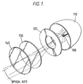
- the optical components of a luminaire for stage, studio or other entertainment use comprise a light source 100 (typically a 500W - 5Kw incandescent lamp) located at one focus of an ellipsoidal reflector 110.
- a light source 100 typically a 500W - 5Kw incandescent lamp
- the gate plate is positioned so that substantially all the beam passes through the central aperture.
- a projection lens system 130,140 collects the light passing through the gate plate 120 and provides a generally focussed beam, with the edges of the aperture of the gate plate approximately in focus on the stage.
- the components 100-140 are housed within a luminaire housing (not shown) and the shutter blades are provided adjacent the gate plate 120.
- the mounting of the luminaire 100 may be as described in our UK patent application no. 9207085.3 filed on 31st March 1992 (agents ref 3251701) incorporated herein by reference.
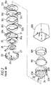
- a rear luminaire housing portion 200 receives the reflector 110 surrounded by a heat baffle 105.
- the gate assembly comprises a rear mounting collar 24 secured to the rear luminaire housing portion 200, and carrying four mounting posts 23a,23b,23c,23d.
- a forward luminaire housing portion (not shown in FIG 2) is secured by screws, to mount the projection lenses 130,140 shown in FIG 1.
- an inner ring plate 22 which receives five separator plate 30a-30e between which are sandwiched four shutter blades 32a-32d, their handles projecting between the mounting posts 23a-23d which define four slots by virtue of the separation between the rear luminaire housing portion 200 and the forward luminaire housing portion.
- an iris 28 located against an upper pressure plate 29, and the upper pressure plate 29 is urged against the separator plates by a collar 27 carrying a plurality of leaf springs 33 and secured to the lower support collar 22 by a screw fitting 25,26.
- the luminaire housing comprises a rearward portion 200 and a forward portion 210; although not shown, the rearward portion 200 includes the reflector 110 and bulb or lamp 100 as in FIG 2, and the forward portion 210 extends forwardly to include the lenses 130,140 shown in FIG 1.
- the rearward portion 200 includes two circumferential slots 201a,201b, and the forward portion 210 includes likewise a pair of slots 202a,202b. Each slot extends over an angle of greater than 360/4° (where 4 is the number of slots), so that no lands exist between the slots.
- the structural connection between the rear portion 200 and the forward portion 210 is provided through the gate plate 120, in other words, the forward and rear halves 200, 210 are only mechanically interconnected through the gate plate 120.
- the luminaire housing 200,210 and gate plate 120 are formed in a single casting operation, with an inner core and two outer moulds.
- gate plate 120 could equally be welded to the rear portion 200 and forward portion 210 or any other method of providing an integral whole could be adopted.
- the gate plate 120 is therefore of sufficient thickness to provide a reliable structural connection between the two halves 200,210 of the luminaire housing.
- the housing/gate plate assembly may conveniently be formed from aluminium; suitable aluminium die casting techniques are well known.
- each slot 201a, 201b, 202a-202b a shutter plate is insertable, as shown.
- the shutter plate 132a,132b is generally similar to the construction employed in the prior art; that is, it has a handle portion projecting through the slot for manipulation by the operator, and a straight edged blade portion transverse to the axis of the handle portion.
- the slots 202a-202d are sufficiently wide that the blades 132a,132b etc can be inserted and withdrawn through the slots; this is generally not possible with currently available luminaire constructions.
- the shutter blades 132a etc are maintained flat within the plane of the gate plate 120 by providing, for each pair of slots, a pressure plate 127 acting as a spring urging the blades and gate plate together; the pressure plates 127a,127b (not shown) therefore fulfill the general function of the collar 27 of FIG 2.
- Each plate 127 is arranged to be insertable through a respective slot to engage the slot on the opposite side of the luminaire housing (as shown, the plate 127a is insertable through slot 202b so as in use to engage the edges of the slots 202b and 202a) and to exert resilient pressure between the edges of those slots and the shutter blades 132 inserted through those slots.
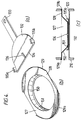
- a shutter blade 132 comprises a handle portion 133 which is elongate and extends backwardly generally transverse to the straight shutter edge 134 (although the handle 133 could be inclined, it is preferred for ease of operation to provide the handle portion 133 normal to the blade 134).
- the land between the edge 134 and handle portion 133 is sufficiently broad that when the blade 134 is extended in normal use into the centre of the aperture within the gate plate 120, the rear edge of the land is not visible within the central orifice; some degree of curvature of the trailing edge is also preferred to reduce friction on the inner surface of the luminaire assembly.
- the shape of the land is not critical.
- a pair of edge retaining features 135a,135b are provided which prevent the edges of the shutter blade 134 projecting through the central orifice in the gate plate 120. As shown the edge retaining features 135a,135b are conveniently provided as upturned tabs at the edge of the shutter plate 132.
- the shutter plate 132 is of narrower overall width than the width of the slot 202 through which it is inserted, a blade retention feature is provided on the blade 132; the blade retention feature 136 conveniently comprises a barb sloping backwardly towards the handle portion 133, so as to allow the shutter blade to be readily inserted but not removed.
- the shutter blade 132 is conveniently provided as a stainless steel pressing, and the barb 136 as a semi-pierce on the pressing.
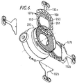
- the spring plate 127 comprises an upper land 128 in the form of a generally ring shaped flat sheet, of outer diameter corresponding to that of the luminaire housing 210; the opposed sides of the ring 128 are truncated so as to limit the width of the plate 128 to be smaller than that of the slots 202 so that the plate 127 is insertable through the slots.
- the upper land 128 bears against the edges of the slots 202 in use.
- a pair of upturned rims 129a,129b are provided at either end of the plate 127, to engage the edges of the slots 202 on the outside of the luminaire housing 210 and laterally retain the plate 127 within the housing in use.
- a frustoconical surface 150 at the lower edge of which is an inner annular ring 151 of inner diameter equal to or greater than the central aperture within the gate plate 120, so as not to obtrude into the central aperture of the gate plate.
- Splits (not shown) in the edges of the inner ring 151 and for 127 and 150 may be provided to localise the pressure exerted on the shutter blades 132 so that distortion of one shutter blade does not affect the retention of the other.
- the pressure plate is formed as a stainless steel pressing.
- the pressure plate 127 shows, in cross-section, a lazy-Z shape providing a spring force between the upper land or ring 128 and the inner ring 151; since the upper ring 128 bears against the forward part of the luminaire housing at the forward edge of the slots 202, the inner ring 151 is urged towards the shutter blade 135 and gate plate 120, biassing the two together.
- the frustoconical portion 150 has a height corresponding generally to the height of the slot 202, and thus prevents light loss through the slots 202.
- the pressure plate 127 exerts a resilient force which not only retains the shutter blade 132 within the luminaire housing, but also retains the pressure plate 127 itself, by virtue of the rims 129. This will be seen to greatly reduce the complexity of the assembly, as compared with the prior art for, for example, FIG 2, enabling this embodiment to operate entirely without screws or bolts, which thus greatly reduces the complexity of assembly and disassembly of the luminaire.
- the number of components to be disassembled is reduced from 10 to three and the need for screwdrivers or other tools is greatly reduced with consequent reduction in the time for which the luminaire is inactive whilst the blade and pressure plate is replaced.
- the assembly of the gate and shutters is as follows. Firstly, the pressure plate 127 is inserted through a first slot 202b until the rim 129b engages the outer surface of the luminaire housing 210 (forward portion); as shown, a recessed ring may be provided at the forward edge of the slot 202a to accommodate the rim 129b. Then a shutter blade 132 is inserted through a slot 202b, between the gate plate 120 and the inner ring 151, and urged forward so that the barb 136 enters within the inner ring 151, trapping the shutter blade against accidental removal. The next shutter blade 132 is then inserted through the other slot 129b.
- a further spring plate 127b (not shown) is likewise inserted through the other pair of slots 201a,201b with the outer land 127 bearing this time against the backwards edges of the slots 201a,201b and the inner edges 151 towards the shutter plate 120, and a corresponding further pair of shutter blades 132 are inserted between the second pressure plate 127 and the gate plate 120.
- the shutter plates are withdrawn until the barb 136 locates against the inner rim 151.
- a convenient tool for example, a screwdriver
- the inner rim 151 away from the shutter blade 132 to the extent necessary to withdraw the barb 136.
- the blades 132 are withdrawn it is then possible to remove the pressure plate 127 through one of the slots 129a or 129b.
- a blade 132 in use, can be rotated through an angle in excess of 90° (or, in general, 360/n° where n is the number of blades) by manipulation of the handle 133, and that the tabs 135 engage with the shutter plate 127 to prevent the corners of the blade entering within the gate aperture.
- the edges of a pair of blades through opposed slots 202a,202b may therefore be brought parallel to one another if desired, or even manipulated further so that the two handle portions 133 define an acute angle, rather than the obtuse angles necessary in the prior art. A much greater range of beam shapes are therefore available to the lighting designer.
- the shutter blades and pressure plate may be of stainless steel sheet thickness of SWG24.22 and the luminaire housing and gate plate assembly 210,120 of aluminium alloy thickness 2.0-2.5mm, die cast.
- any other materials suitable for the mechanical and thermal conditions well known to exist within luminaires could equally be used.
- the pressure plate 127 is conveniently inserted through the same slots as the shutter blade, but separate slots could be provided if desired for this purpose, or alternative fastenings provided internally within the housing 200.
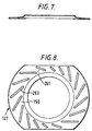
- each pressure plate 127a, 127b is provided with a series of slats 261 formed from the frustoconical surface 150 and upper land surfaces 158 by piercing a corresponding series of slots 263.
- the slats 261 are designed to have differing lengths and are arranged over the plate 127 so as to ensure that there is a substantially even spring pressure over the contact surfaces, avoiding the problem of tight or loose spots.
- the corresponding slots 263 enable better ventilation of the housing 200.
Landscapes
- Engineering & Computer Science (AREA)
- General Engineering & Computer Science (AREA)
- Non-Portable Lighting Devices Or Systems Thereof (AREA)
Applications Claiming Priority (2)
| Application Number | Priority Date | Filing Date | Title |
|---|---|---|---|
| GB9207048A GB2265975B (en) | 1992-03-31 | 1992-03-31 | Luminaire |
| GB9207048 | 1992-03-31 |
Publications (3)
| Publication Number | Publication Date |
|---|---|
| EP0563483A2 EP0563483A2 (en) | 1993-10-06 |
| EP0563483A3 EP0563483A3 (enExample) | 1994-03-23 |
| EP0563483B1 true EP0563483B1 (en) | 1997-01-22 |
Family
ID=10713197
Family Applications (1)
| Application Number | Title | Priority Date | Filing Date |
|---|---|---|---|
| EP92310392A Expired - Lifetime EP0563483B1 (en) | 1992-03-31 | 1992-11-13 | Luminaire comprising shutter blades |
Country Status (5)
| Country | Link |
|---|---|
| US (1) | US5510969A (enExample) |
| EP (1) | EP0563483B1 (enExample) |
| DE (1) | DE69217041T2 (enExample) |
| GB (1) | GB2265975B (enExample) |
| NZ (1) | NZ245143A (enExample) |
Families Citing this family (26)
| Publication number | Priority date | Publication date | Assignee | Title |
|---|---|---|---|---|
| GB2290861A (en) * | 1994-05-26 | 1996-01-10 | Strand Lighting Ltd | Luminaire |
| US5658070A (en) * | 1994-10-27 | 1997-08-19 | Alcon Laboratories, Inc. | Method of varying luminous intensity of light in an illumination system |
| WO1996036834A1 (en) * | 1995-05-18 | 1996-11-21 | Martin Professional A/S | Lighting apparatus, in particular for stage use |
| FR2754041B1 (fr) * | 1996-10-02 | 1998-12-04 | Marechal Dominique | Dispositif permettant l'occultation des rayons lumineux emanant de projecteurs |
| AU2001256145B2 (en) * | 2000-05-03 | 2004-11-18 | N.V Adb Ttv Technologies Sa | A lighting fixture |
| US6744693B2 (en) | 2000-05-03 | 2004-06-01 | N.V. Adb Ttv Technologies Sa | Lighting fixture |
| ITMI20011873A1 (it) * | 2001-09-07 | 2003-03-07 | Clay Paky Spa | Dispositivo sagomatore di fasci luminosi |
| US6550939B2 (en) | 2001-09-12 | 2003-04-22 | Vari-Lite, Inc. | Light beam shutter apparatus |
| FR2838808B1 (fr) | 2002-04-23 | 2005-01-14 | Jacques Biehlmann | Projecteur muni d'un nez specifique de reglage du faisceau lumineux et nez mis en oeuvre |
| US6939026B2 (en) * | 2003-08-28 | 2005-09-06 | Electronic Theatre Controls, Inc. | Shutter assembly for a luminaire |
| US7033047B2 (en) * | 2003-08-28 | 2006-04-25 | Electronic Theatre Controls, Inc. | Compact shutter assembly for a luminaire |
| US7556402B2 (en) * | 2004-03-29 | 2009-07-07 | Cooper Technologies Company | Direct-indirect luminaire with shutter |
| US7195359B1 (en) * | 2005-01-28 | 2007-03-27 | Conti Mario W | Framing projector with adjustable shutter |
| US7517088B1 (en) | 2005-11-28 | 2009-04-14 | Thomas E. Kretzschmar | Light projector |
| WO2007098720A1 (en) * | 2006-03-03 | 2007-09-07 | Robe Show Lighting S.R.O. | Optical system |
| US7444057B2 (en) * | 2007-03-16 | 2008-10-28 | Alcon, Inc. | Variable-wedge rotating-disk beam attenuator for ophthalmic endoilluminator |
| US7499624B2 (en) * | 2007-03-16 | 2009-03-03 | Alcon, Inc. | Ophthalmic Endoilluminator with Variable-Wedge Rotating-Disk Beam Attenuator |
| US20090002998A1 (en) * | 2007-06-29 | 2009-01-01 | Christie Digital Systems Canada, Inc. | Reflective iris |
| AU2009200881A1 (en) * | 2009-03-06 | 2010-09-23 | Selecon New Zealand Limited | Shutter lock |
| TWI453460B (zh) * | 2010-07-08 | 2014-09-21 | 兆光科技有限公司 | 用於發光二極體顯示器之可變間隔快門 |
| US9458991B2 (en) * | 2010-11-09 | 2016-10-04 | Peter Jacksen | Optical framing projector forward access adjustment and locking systems |
| US20140085900A1 (en) * | 2012-09-25 | 2014-03-27 | Mountain Springs Holdings, LLC. | Adjustable Framing Projector |
| US9841154B2 (en) * | 2014-03-15 | 2017-12-12 | Cree, Inc. | Luminaire utilizing light emitting diodes |
| CN109073834B (zh) * | 2016-02-29 | 2020-03-27 | 理想工业照明有限责任公司 | 利用发光二极管的照明器 |
| CN109854994B (zh) * | 2018-12-25 | 2024-08-02 | 赛尔富电子有限公司 | 一种投射灯的光斑调节组件及投射灯 |
| US11692684B2 (en) * | 2021-02-18 | 2023-07-04 | Designspark, Llc | Filtering assembly for enhancing lighting from a luminaire |
Family Cites Families (4)
| Publication number | Priority date | Publication date | Assignee | Title |
|---|---|---|---|---|
| GB1063392A (en) * | 1963-09-13 | 1967-03-30 | Strand Electric And Engineerin | Improvements in or relating to spotlights |
| DE7707291U1 (de) * | 1977-03-09 | 1977-07-28 | Bischl, Johann, 8000 Muenchen | Vorrichtung zum abblenden einer lichtquelle |
| US4210955A (en) * | 1977-03-14 | 1980-07-01 | Electro Controls Inc. | Shutter system for stage-lighting spotlights |
| JPS5926081B2 (ja) * | 1978-07-10 | 1984-06-23 | 昌 荒井 | 照明器等における可変マスク装置 |
-
1992
- 1992-03-31 GB GB9207048A patent/GB2265975B/en not_active Expired - Fee Related
- 1992-11-13 EP EP92310392A patent/EP0563483B1/en not_active Expired - Lifetime
- 1992-11-13 DE DE69217041T patent/DE69217041T2/de not_active Expired - Fee Related
- 1992-11-16 NZ NZ245143A patent/NZ245143A/en unknown
- 1992-11-16 US US07/977,278 patent/US5510969A/en not_active Expired - Fee Related
Also Published As
| Publication number | Publication date |
|---|---|
| GB2265975A (en) | 1993-10-13 |
| GB2265975B (en) | 1996-02-21 |
| EP0563483A3 (enExample) | 1994-03-23 |
| EP0563483A2 (en) | 1993-10-06 |
| DE69217041D1 (de) | 1997-03-06 |
| GB9207048D0 (en) | 1992-05-13 |
| US5510969A (en) | 1996-04-23 |
| NZ245143A (en) | 1994-06-27 |
| DE69217041T2 (de) | 1997-08-07 |
Similar Documents
| Publication | Publication Date | Title |
|---|---|---|
| EP0563483B1 (en) | Luminaire comprising shutter blades | |
| USD359374S (en) | Light fixture | |
| WO1996014960A3 (en) | Universal polishing fixture for polishing optical fiber connectors | |
| USD411324S (en) | Under cabinet halogen light bar with single rectangular lens bezel | |
| CN100516637C (zh) | 用于变换旋转遮光片的设备 | |
| CA1140096A (en) | Universally adjustable lamp fixture | |
| US4109301A (en) | Adaptor for photographic flash device | |
| USD320283S (en) | Fluorescent lighting fixture grill | |
| USD354579S (en) | Pendant light fixture | |
| US4302078A (en) | Photographic filter holder with threaded adapter | |
| US6808295B2 (en) | Light modifier mounting assembly | |
| USD375374S (en) | Multi-fluorescent lantern with emergency light | |
| USD362079S (en) | Portable clip-on safety light | |
| USD332318S (en) | Suspended diffused lighting fixture for commercial films and photography | |
| US6832845B1 (en) | Contour light projector | |
| TW349173B (en) | Optical system rendering an object visible in a scattering media | |
| US5921662A (en) | Adapter for general-diffuse miniature reflectors | |
| US20070014563A1 (en) | Ring-shaped Luminaire | |
| EP0684424A1 (en) | Luminaire | |
| US9458991B2 (en) | Optical framing projector forward access adjustment and locking systems | |
| JPH02107112U (enExample) | ||
| USD361609S (en) | Target for hockey practice | |
| EP1847872B1 (en) | Mattebox with flag position fixation and tiltable filter unit | |
| DE102004042802A1 (de) | Strahler | |
| EP0268570B1 (en) | Sun visor with mirror lighting and pivoted cover |
Legal Events
| Date | Code | Title | Description |
|---|---|---|---|
| PUAI | Public reference made under article 153(3) epc to a published international application that has entered the european phase |
Free format text: ORIGINAL CODE: 0009012 |
|
| AK | Designated contracting states |
Kind code of ref document: A2 Designated state(s): BE DE FR GB IT |
|
| PUAL | Search report despatched |
Free format text: ORIGINAL CODE: 0009013 |
|
| AK | Designated contracting states |
Kind code of ref document: A3 Designated state(s): BE DE FR GB IT |
|
| 17P | Request for examination filed |
Effective date: 19940915 |
|
| 17Q | First examination report despatched |
Effective date: 19950516 |
|
| GRAG | Despatch of communication of intention to grant |
Free format text: ORIGINAL CODE: EPIDOS AGRA |
|
| GRAH | Despatch of communication of intention to grant a patent |
Free format text: ORIGINAL CODE: EPIDOS IGRA |
|
| GRAH | Despatch of communication of intention to grant a patent |
Free format text: ORIGINAL CODE: EPIDOS IGRA |
|
| GRAA | (expected) grant |
Free format text: ORIGINAL CODE: 0009210 |
|
| AK | Designated contracting states |
Kind code of ref document: B1 Designated state(s): BE DE FR GB IT |
|
| ET | Fr: translation filed | ||
| REF | Corresponds to: |
Ref document number: 69217041 Country of ref document: DE Date of ref document: 19970306 |
|
| ITF | It: translation for a ep patent filed | ||
| PLBE | No opposition filed within time limit |
Free format text: ORIGINAL CODE: 0009261 |
|
| 26N | No opposition filed | ||
| PGFP | Annual fee paid to national office [announced via postgrant information from national office to epo] |
Ref country code: GB Payment date: 20001030 Year of fee payment: 9 |
|
| PGFP | Annual fee paid to national office [announced via postgrant information from national office to epo] |
Ref country code: BE Payment date: 20011031 Year of fee payment: 10 |
|
| PG25 | Lapsed in a contracting state [announced via postgrant information from national office to epo] |
Ref country code: GB Free format text: LAPSE BECAUSE OF NON-PAYMENT OF DUE FEES Effective date: 20011113 |
|
| PGFP | Annual fee paid to national office [announced via postgrant information from national office to epo] |
Ref country code: FR Payment date: 20011127 Year of fee payment: 10 |
|
| REG | Reference to a national code |
Ref country code: GB Ref legal event code: IF02 |
|
| PGFP | Annual fee paid to national office [announced via postgrant information from national office to epo] |
Ref country code: DE Payment date: 20020129 Year of fee payment: 10 |
|
| PG25 | Lapsed in a contracting state [announced via postgrant information from national office to epo] |
Ref country code: BE Free format text: LAPSE BECAUSE OF NON-PAYMENT OF DUE FEES Effective date: 20021130 |
|
| BERE | Be: lapsed |
Owner name: *STRAND LIGHTING LTD Effective date: 20021130 |
|
| PG25 | Lapsed in a contracting state [announced via postgrant information from national office to epo] |
Ref country code: DE Free format text: LAPSE BECAUSE OF NON-PAYMENT OF DUE FEES Effective date: 20030603 |
|
| PG25 | Lapsed in a contracting state [announced via postgrant information from national office to epo] |
Ref country code: FR Free format text: LAPSE BECAUSE OF NON-PAYMENT OF DUE FEES Effective date: 20030731 |
|
| REG | Reference to a national code |
Ref country code: FR Ref legal event code: ST |
|
| PG25 | Lapsed in a contracting state [announced via postgrant information from national office to epo] |
Ref country code: IT Free format text: LAPSE BECAUSE OF NON-PAYMENT OF DUE FEES;WARNING: LAPSES OF ITALIAN PATENTS WITH EFFECTIVE DATE BEFORE 2007 MAY HAVE OCCURRED AT ANY TIME BEFORE 2007. THE CORRECT EFFECTIVE DATE MAY BE DIFFERENT FROM THE ONE RECORDED. Effective date: 20051113 |