EP0562688A1 - Device for unloading a container for parcel goods, more particularly for postal parcels - Google Patents
Device for unloading a container for parcel goods, more particularly for postal parcels Download PDFInfo
- Publication number
- EP0562688A1 EP0562688A1 EP93200830A EP93200830A EP0562688A1 EP 0562688 A1 EP0562688 A1 EP 0562688A1 EP 93200830 A EP93200830 A EP 93200830A EP 93200830 A EP93200830 A EP 93200830A EP 0562688 A1 EP0562688 A1 EP 0562688A1
- Authority
- EP
- European Patent Office
- Prior art keywords
- container
- unloading
- frame
- unloading door
- swing
- Prior art date
- Legal status (The legal status is an assumption and is not a legal conclusion. Google has not performed a legal analysis and makes no representation as to the accuracy of the status listed.)
- Granted
Links
- 238000007599 discharging Methods 0.000 claims abstract description 17
- 230000008878 coupling Effects 0.000 claims description 9
- 238000010168 coupling process Methods 0.000 claims description 9
- 238000005859 coupling reaction Methods 0.000 claims description 9
- 230000007246 mechanism Effects 0.000 description 7
- 230000004913 activation Effects 0.000 description 2
- 230000000694 effects Effects 0.000 description 2
- 230000008901 benefit Effects 0.000 description 1
- 238000009432 framing Methods 0.000 description 1
- 238000000034 method Methods 0.000 description 1
- 230000002028 premature Effects 0.000 description 1
- 230000008569 process Effects 0.000 description 1
- 230000000284 resting effect Effects 0.000 description 1
- 230000003068 static effect Effects 0.000 description 1
Images
Classifications
-
- B—PERFORMING OPERATIONS; TRANSPORTING
- B65—CONVEYING; PACKING; STORING; HANDLING THIN OR FILAMENTARY MATERIAL
- B65G—TRANSPORT OR STORAGE DEVICES, e.g. CONVEYORS FOR LOADING OR TIPPING, SHOP CONVEYOR SYSTEMS OR PNEUMATIC TUBE CONVEYORS
- B65G65/00—Loading or unloading
- B65G65/23—Devices for tilting and emptying of containers
Definitions
- the invention lies in the field of the transportation and the handling of parcel goods. It relates to a device for unloading a container for parcel goods, more particularly for postal parcels.
- the second problem is that of the load of parcel goods sticking in the container. Sticking occurs due to, for example, so-called arching. This means that parcel goods become jammed between the side walls of the container, with the result that the unloading of at least a part of the parcel goods comes to a standstill, or is even blocked. This can mean that either a container is not completely unloaded, or the parcel goods which have become jammed eventually become dislodged after some time and fall down, with a greatly increased risk of damage.
- the parcel goods are postal parcels, which are generally block-shaped and are stacked at great density in the container, the chance of arching during unloading is great.
- Another form of sticking can occur in the case of containers with open-work walls, formed by, for example, barred or latticed framing, in which parcel goods can become stuck.
- the front side is usually kept shut by means of a shut-off wall during the tilting.
- a tilting device in which this shut-off wall is designed as a simultaneously tilting conveyor belt which in the unloading position acts as the discharging conveyor belt is known in practice. This known solution partially solves the problem of the falling height, but not the problem of goods sticking.
- the shut-off wall is formed by one or two unloading flaps, which in the unloading position are opened, above a simultaneously tilting conveyor belt.
- the unloading flaps are rotatable about parallel axes in the plane of the shut-off wall.
- the simultaneously tilting conveyor belt is situated at a distance just outside the turning circle of each of the unloading flaps.
- the object is to provide a device for unloading containers containing parcel goods, more particularly postal parcels, which limits the chance of damage during the unloading.
- a device for unloading a container for parcel goods, more particularly for postal parcels comprising:
- the object is to provide a device for unloading containers equipped with a rotatable side wall and containing parcel goods, more particularly postal parcels, which not only limits the risk of damage during unloading, but also virtually completely eliminates the chance of sticking.
- a device for unloading a container for parcel goods, more particularly for postal parcels, which container is provided with a side wall which, for the purpose of increasing the area of the open front side of the container, is rotatable about an axis of rotation in or near the plane of the side wall, and having the characteristics mentioned in the previous paragraph, for this purpose according to the invention is further characterised in that the unloading door is provided with coupling means for coupling to the rotatable side wall and for taking along the rotating side wall in the coupled state while it is being swung open.
- the invention is based on the idea that the position of the swing axis of the unloading door can be selected in such a way that the parcel goods to be unloaded, when they are at a suitable height above the discharging conveyor, can be, as it were, laid down on the conveyor belt by the opening door, preferably interacting with a suitably disposed guide wall. If, in addition, a container with rotatable side wall which is known per se, for example from reference [2] is used, the open front side and the space between the side walls of the container can be enlarged in a simple way during unloading by adding a simple carrier coupling between the unloading door and said rotatable side wall, with the result that the chance of arching almost entirely disappears.
- the device according to the invention is used for unloading containers with an open front side.
- the containers are mobile.
- Such containers are also known as roll containers.
- the unloading takes place by tilting a roll container from a set-up position with the open front side forward until it is in an unloading position above a discharging conveyor belt. During this tilting, the open side is kept closed until the unloading position is reached.
- the tilting generally takes place about a horizontal tilting axis.
- This tilting axis can be selected essentially parallel to the discharge direction of the conveyor belt, which means that the roll container is tilted from a set-up position next to the conveyor belt.
- the tilting can also take place about a tilting axis essentially at right angles to the discharge direction from a set-up position in line with the conveyor belt.
- the second option is selected in the example of an embodiment.
- the device according to the invention comprises a surrounding frame 1, which forms the static environment for a tilting set-up frame 2 for a roll container 3, as shown in the drawing.
- the known roll container used in the example of an embodiment has a vertical rear wall 3.1, a flap-up bottom 3.2, two side walls 3.3 and 3.4, and three wheels 3.5, and also a wheel 3.6.
- Side wall 3.4 is rotatable about a vertical axis near the rear wall 3.1 when the bottom 3.2 has been/is being lifted.
- Wheel 3.6 (see Fig. 4), near the open front side, is fitted on the bottom of the rotatable side wall 3.4.
- the set-up frame 2 is formed by two parallel frameworks 6 and 7, rigidly connected to each other by means of transverse connections 8 along the top and bottom. Approximately half of the the space between the frameworks 6 and 7 is taken up by a set-up space for setting up a roll container 3.
- the set-up space is bounded at the bottom by a floor plate 4, at one vertical side by a side wall 9 which is fixed relative to the floor plate 4, at the front by an unloading door 10, which is swivellably suspended in the set-up frame 2 about halfway between the frameworks 6 and 7, by means of L-shaped swing arms 11 and 12, and at the other vertical side by a side wall 13 which is fixed on the swing arms 11 and 12 and connects to the unloading door 10.
- a roll container to be unloaded is wheeled in through the open rear side of the set-up space, with its open front side in the direction of the unloading door 10, onto the floor plate 4 up to a threshold-type stop 5.
- a fork 41 which is fixed to the bottom side of the side wall 13, and which grips around the wheel 3.6 when a roll container is wheeled in.
- a push-up mechanism 42 for example hydraulically driven, is fitted on the floor plate 4, by which mechanism the bottom 3.2 of a roll container 3 set up in the set-up space can be lifted, or at any rate pushed up so far that the side wall 3.4 becomes rotatable.
- the unloading door 10 can swing about a swing axis 14; this swing axis is situated essentially vertical to the floor plate 4, in the plane of the open rear side of the set-up space and near the place where the axis of rotation of the rotatable side wall 3.4 of a roll container 3 to be unloaded is situated.
- a hydraulic cylinder coupling 15 between framework 7, and a connecting piece (not shown) between the swing arms 11 and 12 forms the drive mechanism for the swing movement of the door, for which the other half of the space between the frameworks 6 and 7 is used.
- the set-up frame 2 can tilt about a horizontal tilting axis 16 formed by the points of rotation of rotating connections between attachments 17 and 18 fixed on the frameworks 6 and 7 and corresponding elevations 19 and 20 of the surrounding frame 1.
- the drive mechanism for the tilting movement of the set-up frame about the tilting axis 16 consists of a pair of hydraulic cylinder couplings 21 and 22 fitted at some distance above and at right angles to the tilting axis 16 between upright frame parts 23 and 24 of the surrounding frame 1 and the frameworks 6 and 7.
- a conveyor belt 25 extends from the tilting axis 16, which conveyor belt can be driven by means of a drum motor 26, and is a width which corresponds to the width of the unloading door 10 shutting off the open front side of the roll container 3.
- a guide wall 27 is fitted along the side of the conveyor belt 25, which corresponds to the fixed side wall 9 of the set-up space.
- the roll container 3 Before tilting, the roll container 3 is locked in the set-up space by means of clamping means on the rear wall of the roll container 3. Simple clamping screws or even hydraulically driven claw-type devices which grip from the set-up frame 2, for example on the side of the rear wall, can be selected for this.
- a supporting pin 28 is also provided on framework 6, at a height directly above the side wall 3.3 of the roll container, by means of which pin the roll container 3 is prevented from shooting off forward during the tilting, should the clamping on the rear wall 3.1 prove inadequate.
- the tilting movement is initiated by activation of the drive mechanism formed by the hydraulic couplings 21 and 22.
- the set-up frame 2 is pulled forward and lifted up slightly until it is in a position above the conveyor belt 25, while the plane of the still closed door 10 is approximately parallel to the conveying plane of the conveyor belt 25. This is the unloading position.
- the device is shown in this position in a side view in Fig. 3 and in a front view in Fig. 4.
- the push-up mechanism 42 on the floor plate 4 by which the bottom 3.2 of the roll container 3 is lifted, is also activated, as a result of which the side wall 3.4 becomes rotatable.
- the swing movement of the unloading door is then initiated by activation of the drive mechanism formed by the hydraulic coupling 15.
- the position of the swing axis and the dimensions of the unloading door are selected in such a way that when the unloading door 10 is swung from the closed position to the open end position (indicated in Fig. 4 by the double arrow A ⁇ B) the outer edge 10.1 of the unloading door 10 swings/moves just along the guide wall 27 and along the conveying face of the conveyor belt 25.
- Parcel goods to be unloaded which in the unloaded state are generally already resting against the inside of the unloading door 10, are consequently, as it were, spread down or laid down on the surfaces of the guide wall 13 and the conveyor belt 25 lying below.
- the open end position of the unloading door 10 is preferably such that the inside of the unloading door in that position forms a guide wall corresponding to the guide wall 27 at the opposite side of the conveyor belt 25.
- the discharging conveyor belt is selected so that it slants slightly, on account of the handling height lying behind it. It also has a slight advantage in terms of energy in that a roll container has to be lifted slightly less high and tilted slightly less far.
- the height of the unloading door 10 and the side wall connecting thereto is preferably greater than the height of the roll container, in order to catch any parcel goods which might roll over the top during the tilting movement.
Landscapes
- Engineering & Computer Science (AREA)
- Mechanical Engineering (AREA)
- Types And Forms Of Lifts (AREA)
- Specific Conveyance Elements (AREA)
- Control And Other Processes For Unpacking Of Materials (AREA)
- Loading Or Unloading Of Vehicles (AREA)
- Handcart (AREA)
Abstract
Description
- The invention lies in the field of the transportation and the handling of parcel goods. It relates to a device for unloading a container for parcel goods, more particularly for postal parcels.
- For the transportation and handling of postal parcels use is generally made of more or less cage-shaped containers travelling on wheels, also called roll containers, with an open front side through which the containers can be loaded and unloaded. In order to be able to process individually the parcel goods which form the contents of loaded containers, which processing can involve sorting and distribution of the parcel goods, it is customary to tilt such containers in special tilting devices from a set-up position, in which the container is wheeled in, to an unloading position, in which the open front side of the container lies at least partially above a discharging conveyor belt onto which the contents can be unloaded.
- Two problems generally occur during unloading. First of all, there is the problem that during unloading undesirable falling heights can arise, with an increased chance of damage. The second problem is that of the load of parcel goods sticking in the container. Sticking occurs due to, for example, so-called arching. This means that parcel goods become jammed between the side walls of the container, with the result that the unloading of at least a part of the parcel goods comes to a standstill, or is even blocked. This can mean that either a container is not completely unloaded, or the parcel goods which have become jammed eventually become dislodged after some time and fall down, with a greatly increased risk of damage. In particular, if the parcel goods are postal parcels, which are generally block-shaped and are stacked at great density in the container, the chance of arching during unloading is great. Another form of sticking can occur in the case of containers with open-work walls, formed by, for example, barred or latticed framing, in which parcel goods can become stuck. In order to prevent premature unloading, the front side is usually kept shut by means of a shut-off wall during the tilting.
- A tilting device in which this shut-off wall is designed as a simultaneously tilting conveyor belt which in the unloading position acts as the discharging conveyor belt is known in practice. This known solution partially solves the problem of the falling height, but not the problem of goods sticking.
- In another tilting device, known from reference [1], and more particularly intended for unloading containers with mail bags, the shut-off wall is formed by one or two unloading flaps, which in the unloading position are opened, above a simultaneously tilting conveyor belt. The unloading flaps are rotatable about parallel axes in the plane of the shut-off wall. The simultaneously tilting conveyor belt is situated at a distance just outside the turning circle of each of the unloading flaps. Although a greater falling height to the discharging conveyor can occur here, with controlled opening of the unloading flaps the contents of the container can to some extent slide in the direction of the discharging conveyor, with the result that the effect of the greater falling height is limited. Where only one unloading flap is used, this sliding effect could be increased, but the radius of the turning circle, and consequently the possible falling height to the discharging conveyor belt, is twice as great. Besides, this known solution also does not solve the problem of goods sticking. The chance of arching is even increased, due to the fact that when the unloading flaps are open, the unloading opening is narrower than the open front side of the container used.
- According to a first aspect of the invention, the object is to provide a device for unloading containers containing parcel goods, more particularly postal parcels, which limits the chance of damage during the unloading. A device for unloading a container for parcel goods, more particularly for postal parcels, comprising:
- a frame provided with a set-up space for a container and an unloading door which is suspended so that it can swing in the frame, and against which a container to be unloaded, and having an open front side, can be placed in the set-up space, and
- a discharging conveyor,
- According to a second aspect of the invention, the object is to provide a device for unloading containers equipped with a rotatable side wall and containing parcel goods, more particularly postal parcels, which not only limits the risk of damage during unloading, but also virtually completely eliminates the chance of sticking. A device for unloading a container for parcel goods, more particularly for postal parcels, which container is provided with a side wall which, for the purpose of increasing the area of the open front side of the container, is rotatable about an axis of rotation in or near the plane of the side wall, and having the characteristics mentioned in the previous paragraph, for this purpose according to the invention is further characterised in that the unloading door is provided with coupling means for coupling to the rotatable side wall and for taking along the rotating side wall in the coupled state while it is being swung open.
- The invention is based on the idea that the position of the swing axis of the unloading door can be selected in such a way that the parcel goods to be unloaded, when they are at a suitable height above the discharging conveyor, can be, as it were, laid down on the conveyor belt by the opening door, preferably interacting with a suitably disposed guide wall. If, in addition, a container with rotatable side wall which is known per se, for example from reference [2] is used, the open front side and the space between the side walls of the container can be enlarged in a simple way during unloading by adding a simple carrier coupling between the unloading door and said rotatable side wall, with the result that the chance of arching almost entirely disappears.
-
- [1] NL-A-8301397, entitled: Inrichting voor het lossen van een houder voor stukgoederen, meer in het bijzonder voor postzakken (Device for unloading a container for parcel goods, more particularly for mail bags);
- [2] NL-C-145504, entitled: Handwagen voor het vervoeren van goederen, zoals postzakken, pakketten en dergelijke (Trolley for transporting goods such as mail bags, parcels and the like).
- The invention will be explained in greater detail by means of a description of an example of an embodiment with reference to a drawing, in which:
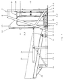
- Fig. 1 is a side view of a device according to the invention, in the set-up position, with a container wheeled in;
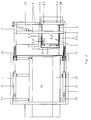
- Fig. 2 is a top view of the device in the set-up position, with a container wheeled in;
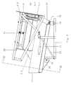
- Fig. 3 is a side view of the device in the unloading position, with open unloading door;
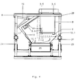
- Fig. 4 is a front view of the device, also in the unloading position, showing two extreme positions of the unloading door, viewed in a direction indicated in Fig. 3.
- The device according to the invention is used for unloading containers with an open front side. Although the invention is not limited thereto, it will be assumed in the description that the containers are mobile. Such containers are also known as roll containers. The unloading takes place by tilting a roll container from a set-up position with the open front side forward until it is in an unloading position above a discharging conveyor belt. During this tilting, the open side is kept closed until the unloading position is reached. The tilting generally takes place about a horizontal tilting axis. This tilting axis can be selected essentially parallel to the discharge direction of the conveyor belt, which means that the roll container is tilted from a set-up position next to the conveyor belt. The tilting can also take place about a tilting axis essentially at right angles to the discharge direction from a set-up position in line with the conveyor belt. The second option is selected in the example of an embodiment.
- In an example of an embodiment, the device according to the invention comprises a surrounding
frame 1, which forms the static environment for a tilting set-up frame 2 for aroll container 3, as shown in the drawing. First of all, the device is described with reference to Fig. 1 in side view and Fig. 2 in top view, with aroll container 3 in the set-up position. The known roll container used in the example of an embodiment has a vertical rear wall 3.1, a flap-up bottom 3.2, two side walls 3.3 and 3.4, and three wheels 3.5, and also a wheel 3.6. Side wall 3.4 is rotatable about a vertical axis near the rear wall 3.1 when the bottom 3.2 has been/is being lifted. Wheel 3.6 (see Fig. 4), near the open front side, is fitted on the bottom of the rotatable side wall 3.4. - The set-up
frame 2 is formed by twoparallel frameworks transverse connections 8 along the top and bottom. Approximately half of the the space between theframeworks roll container 3. The set-up space is bounded at the bottom by afloor plate 4, at one vertical side by aside wall 9 which is fixed relative to thefloor plate 4, at the front by anunloading door 10, which is swivellably suspended in the set-upframe 2 about halfway between theframeworks shaped swing arms side wall 13 which is fixed on theswing arms unloading door 10. A roll container to be unloaded is wheeled in through the open rear side of the set-up space, with its open front side in the direction of the unloadingdoor 10, onto thefloor plate 4 up to a threshold-type stop 5. In the set-up space, just above thefloor plate 4, there is afork 41 which is fixed to the bottom side of theside wall 13, and which grips around the wheel 3.6 when a roll container is wheeled in. A push-upmechanism 42, for example hydraulically driven, is fitted on thefloor plate 4, by which mechanism the bottom 3.2 of aroll container 3 set up in the set-up space can be lifted, or at any rate pushed up so far that the side wall 3.4 becomes rotatable. The unloadingdoor 10 can swing about aswing axis 14; this swing axis is situated essentially vertical to thefloor plate 4, in the plane of the open rear side of the set-up space and near the place where the axis of rotation of the rotatable side wall 3.4 of aroll container 3 to be unloaded is situated. Ahydraulic cylinder coupling 15 betweenframework 7, and a connecting piece (not shown) between theswing arms frameworks - The set-up
frame 2 can tilt about ahorizontal tilting axis 16 formed by the points of rotation of rotating connections betweenattachments frameworks corresponding elevations 19 and 20 of thesurrounding frame 1. The drive mechanism for the tilting movement of the set-up frame about the tiltingaxis 16 consists of a pair ofhydraulic cylinder couplings axis 16 betweenupright frame parts surrounding frame 1 and theframeworks closed unloading door 10, but slightly staggered, aconveyor belt 25 extends from the tiltingaxis 16, which conveyor belt can be driven by means of adrum motor 26, and is a width which corresponds to the width of the unloadingdoor 10 shutting off the open front side of theroll container 3. Aguide wall 27 is fitted along the side of theconveyor belt 25, which corresponds to the fixedside wall 9 of the set-up space. - Before tilting, the
roll container 3 is locked in the set-up space by means of clamping means on the rear wall of theroll container 3. Simple clamping screws or even hydraulically driven claw-type devices which grip from the set-upframe 2, for example on the side of the rear wall, can be selected for this. A supportingpin 28 is also provided onframework 6, at a height directly above the side wall 3.3 of the roll container, by means of which pin theroll container 3 is prevented from shooting off forward during the tilting, should the clamping on the rear wall 3.1 prove inadequate. - The tilting movement is initiated by activation of the drive mechanism formed by the
hydraulic couplings frame 2 is pulled forward and lifted up slightly until it is in a position above theconveyor belt 25, while the plane of the still closeddoor 10 is approximately parallel to the conveying plane of theconveyor belt 25. This is the unloading position. The device is shown in this position in a side view in Fig. 3 and in a front view in Fig. 4. During the tilting movement the push-upmechanism 42 on thefloor plate 4, by which the bottom 3.2 of theroll container 3 is lifted, is also activated, as a result of which the side wall 3.4 becomes rotatable. The swing movement of the unloading door is then initiated by activation of the drive mechanism formed by thehydraulic coupling 15. The position of the swing axis and the dimensions of the unloading door are selected in such a way that when the unloadingdoor 10 is swung from the closed position to the open end position (indicated in Fig. 4 by the double arrow A ↔ B) the outer edge 10.1 of the unloadingdoor 10 swings/moves just along theguide wall 27 and along the conveying face of theconveyor belt 25. Parcel goods to be unloaded, which in the unloaded state are generally already resting against the inside of the unloadingdoor 10, are consequently, as it were, spread down or laid down on the surfaces of theguide wall 13 and theconveyor belt 25 lying below. In the swing movement of the unloadingdoor 10 the wheel 3.6 is also pulled along by thefork 41, and the rotating side wall 3.4 of the roll container is thus carried along, with the result that the open front side of theroll container 3 widens, and the space between the side walls 3.3 and 3.4 widens out. In this way parcel goods are prevented as far as possible from remaining behind in the roll container during the unloading, for example through arching. - The open end position of the unloading
door 10 is preferably such that the inside of the unloading door in that position forms a guide wall corresponding to theguide wall 27 at the opposite side of theconveyor belt 25. - The discharging conveyor belt is selected so that it slants slightly, on account of the handling height lying behind it. It also has a slight advantage in terms of energy in that a roll container has to be lifted slightly less high and tilted slightly less far.
- The height of the unloading
door 10 and the side wall connecting thereto is preferably greater than the height of the roll container, in order to catch any parcel goods which might roll over the top during the tilting movement.
Claims (9)
- Device for unloading a container for parcel goods, more particularly for postal parcels, comprising:- a frame provided with a set-up space for a container and an unloading door which is suspended so that it can swing in the frame, and against which a container to be unloaded, and having an open front side, can be placed in the set-up space, and- a discharging conveyor,which frame can be tilted about an essentially horizontal axis between a set-up position, in which the container can be placed in the set-up space and removed from it again, and an unloading position, in which the unloading door can swing open and the container can be unloaded above the discharging conveyor, characterised in that the unloading door can swing in the frame, by means of swing devices, about a swing axis which lies outside the plane of the unloading door.
- Device according to Claim 1, characterised in that in the unloading position the swing axis lies essentially parallel to the discharging face of the conveyor belt.
- Device according to Claim 1 or 2, characterised in that the device also comprises a first guide wall which is fixed relative to the conveyor, for guiding parcel goods unloaded from the container in the direction of the conveyor, which guide wall is placed essentially at a tangent to the turning circle of the unloading door.
- Device according to Claim 3, characterised in that the unloading door swinging open into the unloading position has an end position in which the unloading door forms a second guide wall opposite the fixed guide wall at the other side of the conveyor.
- Device according to Claim 1, 2, 3 or 4, characterised in that the frame is provided with locking means for locking a container in the set-up space, which locking means engage on the container essentially on or near a rear wall opposite the open front side of a container which has been placed in the set-up space.
- Device for unloading a container for parcel goods, more particularly for postal parcels, which container is provided with a side wall, which in order to increase the area of the open front side of the container is rotatable about an axis of rotation in or near the plane of the side wall, comprising:- a frame provided with a set-up space for a container and an unloading door which is suspended so that it can swing in the frame, and against which a container to be unloaded, and having an open front side, can be placed in the set-up space, and- a discharging conveyor,which frame can be tilted about an essentially horizontal axis between a set-up position, in which the container can be placed in the set-up space and removed from it again, and an unloading position, in which the unloading door can swing open and the container can be unloaded above the discharging conveyor, characterised in that the unloading door can swing in the frame, by means of swing devices, about a swing axis which lies outside the plane of the unloading door, essentially parallel to the axis of rotation, and in that the unloading door is provided with coupling means for coupling to the rotatable side wall and for taking along the rotating side wall in the coupled state while it is being swung open.
- Device according to Claim 6, characterised in that the device also has a first guide wall which is set up fixed relative to the conveyor, for guiding parcel goods unloaded from the container in the direction of the conveyor, which guide wall is placed essentially at a tangent to the turning circle of the unloading door.
- Device according to Claim 7, characterised in that the unloading door swinging open into the unloading position has an end position in which the unloading door forms a second guide wall opposite the fixed guide wall at the other side of the conveyor.
- Device according to Claim 6, 7 or 8, characterised in that the frame is provided with locking means for locking a container in the set-up space, which locking means engage upon the container essentially on or near a rear wall opposite the open front side of a container which has been placed in the set-up space.
Applications Claiming Priority (2)
| Application Number | Priority Date | Filing Date | Title |
|---|---|---|---|
| NL9200565 | 1992-03-26 | ||
| NL9200565A NL9200565A (en) | 1992-03-26 | 1992-03-26 | DEVICE FOR UNLOADING A HOLDER FOR PIECES, IN PARTICULAR FOR POSTAL PACKAGES. |
Publications (2)
| Publication Number | Publication Date |
|---|---|
| EP0562688A1 true EP0562688A1 (en) | 1993-09-29 |
| EP0562688B1 EP0562688B1 (en) | 1996-09-18 |
Family
ID=19860615
Family Applications (1)
| Application Number | Title | Priority Date | Filing Date |
|---|---|---|---|
| EP93200830A Expired - Lifetime EP0562688B1 (en) | 1992-03-26 | 1993-03-22 | Device for unloading a container for parcel goods, more particularly for postal parcels |
Country Status (6)
| Country | Link |
|---|---|
| EP (1) | EP0562688B1 (en) |
| AT (1) | ATE142979T1 (en) |
| DE (1) | DE69304758T2 (en) |
| DK (1) | DK0562688T3 (en) |
| ES (1) | ES2092745T3 (en) |
| NL (1) | NL9200565A (en) |
Cited By (6)
| Publication number | Priority date | Publication date | Assignee | Title |
|---|---|---|---|---|
| US6190110B1 (en) * | 1999-09-28 | 2001-02-20 | Systems & Electronics, Inc. | Residual mail detection and container alignment verification and method |
| US6336782B1 (en) * | 1997-09-25 | 2002-01-08 | Siemens Aktiengesellschaft | Method and device for unloading sheet-like objects from containers |
| US6558103B2 (en) | 2001-04-16 | 2003-05-06 | Southworth Products Corporation | Container unloading apparatus |
| WO2014041312A1 (en) | 2012-09-14 | 2014-03-20 | Materials Technologies | Device for progressively unloading stacked loads |
| RU2611670C2 (en) * | 2015-07-21 | 2017-02-28 | Дмитрий Александрович Денисов | Device for unloading of gondola cars with side unloading hatches in floor |
| WO2020193397A1 (en) * | 2019-03-28 | 2020-10-01 | Flextek A/S | Robot combination emptying unit |
Families Citing this family (2)
| Publication number | Priority date | Publication date | Assignee | Title |
|---|---|---|---|---|
| DE102007024670A1 (en) | 2007-05-25 | 2008-12-04 | Deutsche Post Ag | Apparatus and method for unloading articles from a container |
| DE102009033455A1 (en) * | 2009-07-16 | 2010-09-30 | Siemens Aktiengesellschaft | Device for unloading stackable goods from cargo units, particularly from roller containers, has loading unit with open side, which is moved against vertically directed wall surface |
Citations (3)
| Publication number | Priority date | Publication date | Assignee | Title |
|---|---|---|---|---|
| DE3021367A1 (en) * | 1980-06-06 | 1981-12-17 | Luco-Technik GmbH Verfahrenstechnische Anlagen, 6474 Ortenberg | De-palletising mechanism for sacks etc. stacked in layers - has tippable frame with lift bottom, holding rams at top, and side opening closable by top layer |
| NL8301397A (en) * | 1983-04-21 | 1984-11-16 | Antonius Huiberts | Mail sack container unloading feed - has vessel with conveyor below, tilting between vertical and horizontal positions |
| DE3321617A1 (en) * | 1983-06-15 | 1984-12-20 | Fa. Anton Zahoransky, 7868 Todtnau | Apparatus for feeding brush elements |
-
1992
- 1992-03-26 NL NL9200565A patent/NL9200565A/en not_active Application Discontinuation
-
1993
- 1993-03-22 AT AT93200830T patent/ATE142979T1/en not_active IP Right Cessation
- 1993-03-22 DE DE69304758T patent/DE69304758T2/en not_active Expired - Fee Related
- 1993-03-22 DK DK93200830.3T patent/DK0562688T3/da active
- 1993-03-22 EP EP93200830A patent/EP0562688B1/en not_active Expired - Lifetime
- 1993-03-22 ES ES93200830T patent/ES2092745T3/en not_active Expired - Lifetime
Patent Citations (3)
| Publication number | Priority date | Publication date | Assignee | Title |
|---|---|---|---|---|
| DE3021367A1 (en) * | 1980-06-06 | 1981-12-17 | Luco-Technik GmbH Verfahrenstechnische Anlagen, 6474 Ortenberg | De-palletising mechanism for sacks etc. stacked in layers - has tippable frame with lift bottom, holding rams at top, and side opening closable by top layer |
| NL8301397A (en) * | 1983-04-21 | 1984-11-16 | Antonius Huiberts | Mail sack container unloading feed - has vessel with conveyor below, tilting between vertical and horizontal positions |
| DE3321617A1 (en) * | 1983-06-15 | 1984-12-20 | Fa. Anton Zahoransky, 7868 Todtnau | Apparatus for feeding brush elements |
Cited By (7)
| Publication number | Priority date | Publication date | Assignee | Title |
|---|---|---|---|---|
| US6336782B1 (en) * | 1997-09-25 | 2002-01-08 | Siemens Aktiengesellschaft | Method and device for unloading sheet-like objects from containers |
| US6190110B1 (en) * | 1999-09-28 | 2001-02-20 | Systems & Electronics, Inc. | Residual mail detection and container alignment verification and method |
| WO2001023287A1 (en) * | 1999-09-28 | 2001-04-05 | Esco Electronics Corporation | Mail detection verification apparatus and method |
| US6558103B2 (en) | 2001-04-16 | 2003-05-06 | Southworth Products Corporation | Container unloading apparatus |
| WO2014041312A1 (en) | 2012-09-14 | 2014-03-20 | Materials Technologies | Device for progressively unloading stacked loads |
| RU2611670C2 (en) * | 2015-07-21 | 2017-02-28 | Дмитрий Александрович Денисов | Device for unloading of gondola cars with side unloading hatches in floor |
| WO2020193397A1 (en) * | 2019-03-28 | 2020-10-01 | Flextek A/S | Robot combination emptying unit |
Also Published As
| Publication number | Publication date |
|---|---|
| NL9200565A (en) | 1993-10-18 |
| DE69304758D1 (en) | 1996-10-24 |
| DE69304758T2 (en) | 1997-02-20 |
| DK0562688T3 (en) | 1997-03-10 |
| EP0562688B1 (en) | 1996-09-18 |
| ATE142979T1 (en) | 1996-10-15 |
| ES2092745T3 (en) | 1996-12-01 |
Similar Documents
| Publication | Publication Date | Title |
|---|---|---|
| CN110382376B (en) | Transport container with output device and corresponding overhead transport device | |
| CN111936400B (en) | Unloading station and method for unloading a transport goods container loaded with transport goods | |
| US3576265A (en) | Material collection system | |
| US5538391A (en) | Method and apparatus for mechanized loading and unloading | |
| US4995522A (en) | Bottom dumping bulk container apparatus | |
| EP0612302B1 (en) | Apparatus for handling an object and method for aquiring or loading an object | |
| EP0562688B1 (en) | Device for unloading a container for parcel goods, more particularly for postal parcels | |
| US4014458A (en) | Three-function container | |
| US5735661A (en) | Transporter for storing and carrying multiple articles, such as coin collection boxes | |
| US4724656A (en) | Automatic molten substance bagging system | |
| CN208689664U (en) | A kind of system for conveying goods and vending machine | |
| CN213558559U (en) | Tipping bucket type sorting trolley capable of avoiding throwing goods | |
| AU2014100919A4 (en) | Apparatus and Method for Containerised bulk Handling to load and discharge dry bulk goods | |
| CN109178363B (en) | Working method of automatic sand filling device for building | |
| US6913431B2 (en) | Container unloading apparatus | |
| CN109178364B (en) | Automatic sand loading device for building | |
| NZ532375A (en) | Container loader | |
| US6558103B2 (en) | Container unloading apparatus | |
| US3225947A (en) | Dump hopper | |
| CN213536073U (en) | Goods taking rack and goods sorting system | |
| JP2963291B2 (en) | Crop processing equipment | |
| JPH0354026A (en) | Collection and delivery system for cargo | |
| CN221662018U (en) | Bulk cargo loading system of container | |
| KR101653396B1 (en) | Container for carrying bulk cargo | |
| US6848878B2 (en) | Two stage dumper apparatus and method |
Legal Events
| Date | Code | Title | Description |
|---|---|---|---|
| PUAI | Public reference made under article 153(3) epc to a published international application that has entered the european phase |
Free format text: ORIGINAL CODE: 0009012 |
|
| AK | Designated contracting states |
Kind code of ref document: A1 Designated state(s): AT BE CH DE DK ES FR GB GR IE IT LI LU NL PT SE |
|
| 17P | Request for examination filed |
Effective date: 19940310 |
|
| 17Q | First examination report despatched |
Effective date: 19950426 |
|
| GRAG | Despatch of communication of intention to grant |
Free format text: ORIGINAL CODE: EPIDOS AGRA |
|
| GRAH | Despatch of communication of intention to grant a patent |
Free format text: ORIGINAL CODE: EPIDOS IGRA |
|
| GRAH | Despatch of communication of intention to grant a patent |
Free format text: ORIGINAL CODE: EPIDOS IGRA |
|
| GRAA | (expected) grant |
Free format text: ORIGINAL CODE: 0009210 |
|
| AK | Designated contracting states |
Kind code of ref document: B1 Designated state(s): AT BE CH DE DK ES FR GB GR IE IT LI LU NL PT SE |
|
| PG25 | Lapsed in a contracting state [announced via postgrant information from national office to epo] |
Ref country code: GR Free format text: LAPSE BECAUSE OF FAILURE TO SUBMIT A TRANSLATION OF THE DESCRIPTION OR TO PAY THE FEE WITHIN THE PRESCRIBED TIME-LIMIT Effective date: 19960918 |
|
| REF | Corresponds to: |
Ref document number: 142979 Country of ref document: AT Date of ref document: 19961015 Kind code of ref document: T |
|
| REG | Reference to a national code |
Ref country code: CH Ref legal event code: NV Representative=s name: ISLER & PEDRAZZINI AG |
|
| REF | Corresponds to: |
Ref document number: 69304758 Country of ref document: DE Date of ref document: 19961024 |
|
| REG | Reference to a national code |
Ref country code: IE Ref legal event code: FG4D Free format text: 69885 |
|
| ITF | It: translation for a ep patent filed | ||
| REG | Reference to a national code |
Ref country code: ES Ref legal event code: FG2A Ref document number: 2092745 Country of ref document: ES Kind code of ref document: T3 |
|
| ET | Fr: translation filed | ||
| PG25 | Lapsed in a contracting state [announced via postgrant information from national office to epo] |
Ref country code: PT Effective date: 19961218 |
|
| PGFP | Annual fee paid to national office [announced via postgrant information from national office to epo] |
Ref country code: IE Payment date: 19970219 Year of fee payment: 5 |
|
| REG | Reference to a national code |
Ref country code: DK Ref legal event code: T3 |
|
| PLBE | No opposition filed within time limit |
Free format text: ORIGINAL CODE: 0009261 |
|
| STAA | Information on the status of an ep patent application or granted ep patent |
Free format text: STATUS: NO OPPOSITION FILED WITHIN TIME LIMIT |
|
| 26N | No opposition filed | ||
| PG25 | Lapsed in a contracting state [announced via postgrant information from national office to epo] |
Ref country code: IE Free format text: LAPSE BECAUSE OF NON-PAYMENT OF DUE FEES Effective date: 19980322 |
|
| REG | Reference to a national code |
Ref country code: CH Ref legal event code: PFA Free format text: KONINKLIJKE PTT NEDERLAND N.V. TRANSFER- KONINKLIJKE KPN N.V. |
|
| REG | Reference to a national code |
Ref country code: GB Ref legal event code: IF02 |
|
| PGFP | Annual fee paid to national office [announced via postgrant information from national office to epo] |
Ref country code: GB Payment date: 20020222 Year of fee payment: 10 |
|
| PGFP | Annual fee paid to national office [announced via postgrant information from national office to epo] |
Ref country code: CH Payment date: 20020225 Year of fee payment: 10 |
|
| PGFP | Annual fee paid to national office [announced via postgrant information from national office to epo] |
Ref country code: LU Payment date: 20020304 Year of fee payment: 10 Ref country code: DK Payment date: 20020304 Year of fee payment: 10 |
|
| PGFP | Annual fee paid to national office [announced via postgrant information from national office to epo] |
Ref country code: SE Payment date: 20020305 Year of fee payment: 10 |
|
| PGFP | Annual fee paid to national office [announced via postgrant information from national office to epo] |
Ref country code: AT Payment date: 20020307 Year of fee payment: 10 |
|
| PGFP | Annual fee paid to national office [announced via postgrant information from national office to epo] |
Ref country code: DE Payment date: 20020309 Year of fee payment: 10 |
|
| PGFP | Annual fee paid to national office [announced via postgrant information from national office to epo] |
Ref country code: FR Payment date: 20020315 Year of fee payment: 10 |
|
| PGFP | Annual fee paid to national office [announced via postgrant information from national office to epo] |
Ref country code: ES Payment date: 20020320 Year of fee payment: 10 |
|
| PGFP | Annual fee paid to national office [announced via postgrant information from national office to epo] |
Ref country code: BE Payment date: 20020322 Year of fee payment: 10 |
|
| PGFP | Annual fee paid to national office [announced via postgrant information from national office to epo] |
Ref country code: NL Payment date: 20020331 Year of fee payment: 10 |
|
| PG25 | Lapsed in a contracting state [announced via postgrant information from national office to epo] |
Ref country code: LU Free format text: LAPSE BECAUSE OF NON-PAYMENT OF DUE FEES Effective date: 20030322 Ref country code: GB Free format text: LAPSE BECAUSE OF NON-PAYMENT OF DUE FEES Effective date: 20030322 Ref country code: AT Free format text: LAPSE BECAUSE OF NON-PAYMENT OF DUE FEES Effective date: 20030322 |
|
| PG25 | Lapsed in a contracting state [announced via postgrant information from national office to epo] |
Ref country code: SE Free format text: LAPSE BECAUSE OF NON-PAYMENT OF DUE FEES Effective date: 20030323 |
|
| PG25 | Lapsed in a contracting state [announced via postgrant information from national office to epo] |
Ref country code: ES Free format text: LAPSE BECAUSE OF NON-PAYMENT OF DUE FEES Effective date: 20030324 |
|
| PG25 | Lapsed in a contracting state [announced via postgrant information from national office to epo] |
Ref country code: LI Free format text: LAPSE BECAUSE OF NON-PAYMENT OF DUE FEES Effective date: 20030331 Ref country code: DK Free format text: LAPSE BECAUSE OF NON-PAYMENT OF DUE FEES Effective date: 20030331 Ref country code: CH Free format text: LAPSE BECAUSE OF NON-PAYMENT OF DUE FEES Effective date: 20030331 Ref country code: BE Free format text: LAPSE BECAUSE OF NON-PAYMENT OF DUE FEES Effective date: 20030331 |
|
| BERE | Be: lapsed |
Owner name: KONINKLIJKE *PTT NEDERLAND N.V. Effective date: 20030331 |
|
| PG25 | Lapsed in a contracting state [announced via postgrant information from national office to epo] |
Ref country code: NL Free format text: LAPSE BECAUSE OF NON-PAYMENT OF DUE FEES Effective date: 20031001 Ref country code: DE Free format text: LAPSE BECAUSE OF NON-PAYMENT OF DUE FEES Effective date: 20031001 |
|
| EUG | Se: european patent has lapsed | ||
| GBPC | Gb: european patent ceased through non-payment of renewal fee |
Effective date: 20030322 |
|
| REG | Reference to a national code |
Ref country code: CH Ref legal event code: PL |
|
| PG25 | Lapsed in a contracting state [announced via postgrant information from national office to epo] |
Ref country code: FR Free format text: LAPSE BECAUSE OF NON-PAYMENT OF DUE FEES Effective date: 20031127 |
|
| NLV4 | Nl: lapsed or anulled due to non-payment of the annual fee |
Effective date: 20031001 |
|
| REG | Reference to a national code |
Ref country code: FR Ref legal event code: ST |
|
| REG | Reference to a national code |
Ref country code: ES Ref legal event code: FD2A Effective date: 20030324 |
|
| PG25 | Lapsed in a contracting state [announced via postgrant information from national office to epo] |
Ref country code: IT Free format text: LAPSE BECAUSE OF NON-PAYMENT OF DUE FEES;WARNING: LAPSES OF ITALIAN PATENTS WITH EFFECTIVE DATE BEFORE 2007 MAY HAVE OCCURRED AT ANY TIME BEFORE 2007. THE CORRECT EFFECTIVE DATE MAY BE DIFFERENT FROM THE ONE RECORDED. Effective date: 20050322 |