EP0561949B1 - Control system for a transmission of the toroidal-race rolling-traction type - Google Patents
Control system for a transmission of the toroidal-race rolling-traction type Download PDFInfo
- Publication number
- EP0561949B1 EP0561949B1 EP92901359A EP92901359A EP0561949B1 EP 0561949 B1 EP0561949 B1 EP 0561949B1 EP 92901359 A EP92901359 A EP 92901359A EP 92901359 A EP92901359 A EP 92901359A EP 0561949 B1 EP0561949 B1 EP 0561949B1
- Authority
- EP
- European Patent Office
- Prior art keywords
- roller
- carriage
- operating mechanism
- axis
- control system
- Prior art date
- Legal status (The legal status is an assumption and is not a legal conclusion. Google has not performed a legal analysis and makes no representation as to the accuracy of the status listed.)
- Expired - Lifetime
Links
- 230000005540 biological transmission Effects 0.000 title claims description 4
- 230000007246 mechanism Effects 0.000 claims abstract description 28
- 238000006073 displacement reaction Methods 0.000 description 3
- 239000012530 fluid Substances 0.000 description 2
- 238000006243 chemical reaction Methods 0.000 description 1
- 230000004048 modification Effects 0.000 description 1
- 238000012986 modification Methods 0.000 description 1
- 238000005096 rolling process Methods 0.000 description 1
- 239000007787 solid Substances 0.000 description 1
Images
Classifications
-
- F—MECHANICAL ENGINEERING; LIGHTING; HEATING; WEAPONS; BLASTING
- F16—ENGINEERING ELEMENTS AND UNITS; GENERAL MEASURES FOR PRODUCING AND MAINTAINING EFFECTIVE FUNCTIONING OF MACHINES OR INSTALLATIONS; THERMAL INSULATION IN GENERAL
- F16H—GEARING
- F16H15/00—Gearings for conveying rotary motion with variable gear ratio, or for reversing rotary motion, by friction between rotary members
- F16H15/02—Gearings for conveying rotary motion with variable gear ratio, or for reversing rotary motion, by friction between rotary members without members having orbital motion
- F16H15/04—Gearings providing a continuous range of gear ratios
- F16H15/06—Gearings providing a continuous range of gear ratios in which a member A of uniform effective diameter mounted on a shaft may co-operate with different parts of a member B
- F16H15/32—Gearings providing a continuous range of gear ratios in which a member A of uniform effective diameter mounted on a shaft may co-operate with different parts of a member B in which the member B has a curved friction surface formed as a surface of a body of revolution generated by a curve which is neither a circular arc centered on its axis of revolution nor a straight line
- F16H15/36—Gearings providing a continuous range of gear ratios in which a member A of uniform effective diameter mounted on a shaft may co-operate with different parts of a member B in which the member B has a curved friction surface formed as a surface of a body of revolution generated by a curve which is neither a circular arc centered on its axis of revolution nor a straight line with concave friction surface, e.g. a hollow toroid surface
- F16H15/38—Gearings providing a continuous range of gear ratios in which a member A of uniform effective diameter mounted on a shaft may co-operate with different parts of a member B in which the member B has a curved friction surface formed as a surface of a body of revolution generated by a curve which is neither a circular arc centered on its axis of revolution nor a straight line with concave friction surface, e.g. a hollow toroid surface with two members B having hollow toroid surfaces opposite to each other, the member or members A being adjustably mounted between the surfaces
Definitions
- This invention relates to continuously-variable-ratio transmissions (which will be referred to as CVT's) of the toroidal-race, rolling-traction type. It relates in particular to the variators, that is to say the ratio-varying units, of such transmissions in which rollers of variable orientation transmit traction between coaxial and part-toroidal input and output grooves or races, formed on coaxial and rotatable input and output discs respectively. By simultaneously altering the radius from the common axis of the discs at which the rollers make rolling contact with the two races, the relative speeds of the two discs change, so changing the transmitted ratio. While the prior art teaches and the invention will be described with relation to toruses of circular cross-section, the invention includes CVT's in which the torus is generated by rotating any closed figure, of generally circular outline, about a generator line.
- Patent specification GB-A-1078791 shows an example of such a CVT in which each roller carriage is directly connected to a mechanical linkage of levers and other solid actuating components
- specification EP-B-0133330 shows an example of many more recent proposals in which the roller carriages directly contact hydraulic pistons.
- each roller is mounted in an elongated carriage which is in turn positively held at both ends by its actuating mechanism.
- Such a double-ended hold upon each carriage naturally requires many mechanical parts and joints and adds to the size, complexity and cost of the CVT.
- Patent publication WO 90/05860 describes a more recent invention which arose from appreciating that the carriages and rollers of this type of CVT can be effectively held and controlled in a manner which involves far less components and mechanical joints, and which therefore offers the prospect of greater simplicity and cheapness.
- each carriage and roller is controlled by a hydraulic operating mechanism positvely connected to one end of the carriage only, and each roller assembly is located at all times by only three contacts with adjacent components, namely the two disc-roller contacts and the contact with the operating mechanism.
- each roller is mounted, within its carriage, in such a way that both the axis and the centre of the roller are fixed relative to that carriage.
- the present invention arises from appreciating that if for some reason there are advantages in mounting the rollers relative to their carriages in a manner which fixes the roller axis but allows the roller centre some freedom of movement along that axis, it is still possible to achieve a mounting and control of each roller carriage that is comparable in simplicity and cheapness to the mountings described in WO 90/05860.
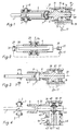
- the invention is defined by the claims, the contents of which are to be read as included within the body of this specification, and includes a roller control system as described with reference to the accompanying simplified drawings. Embodiments of the invention will now be described by way of example with reference to those drawings in which:-
- a roller 1 carrying an axle 2, is mounted in roller bearings 3 supported by a carriage 4. Because they are of roller form, the bearings 3 hold the roller axis 5 fixed relative to carriage 4, but allow the roller centre 6 limited freedom of movement along that axis.
- Carriage 4 is connected by a hinged or other pivotal joint 7, permitting rotation about a single axis 8 only, to a rod 9 forming part of an operating mechanism indicated generally at 10.
- Rod 9 carries pistons 11 and 12 which operate within aligned cylinders 13 and 14, connected by ports 15 and 16 to a controlled pressure fluid source 17.
- the structure of cylinders 13 and 14 is anchored to a fixed part 19 of the CVT.
- the roller In operation, in a manner analogous to that described in publication WO 90/05860, the roller will be positively located by only three points of contact with adjacent mechanism, namely its contacts with the input and output discs (not shown) between which it is transmitting traction, and its point of contact with its operating mechanism 10, which may be regarded as the centre 21 of the hinge joint 7.
- the ratio transmitted by roller between its associated input and output discs is determined by the position of pistons 11, 12 relative to their operating axis 20, and that position in turn reflects the balance between the force (along axis 20) of the disc/roller reactions, and the nett hydraulic force acting upon pistons 11, 12 by reason of the nett hydraulic pressure set up in cylinders 13, 14 by the source 17 and its associated control.
- the necessary degrees of freedom of movement, to allow roller centre 6 to follow its appropriate locus between the input and output discs as the ratio changes, is provided by :-
- Figure 2 shows a minor modification of the axle mounting of Figure 1, in which instead of that axle 2- being free to slide within the roller bearings 3, the bearing members (3a) are fixed to the axle but themselves have limited freedom of axial sliding within their outer sleeves 25.
- Figure 2 also shows, schematically and more importantly, how the mechanism of Figure 1 could be modified if the double-acting piston-and-cylinder combination (11-14) of that Figure were replaced by a single-acting piston and cylinder 26, 27.
- an abutment 28 on the opposite end of carriage 4 now contacts a piston 29, operating within a hydraulic cylinder 30 which may also be controlled from source 17.
- a hinge - e.g. items 7 in Figures 1 to 3, and the hinge about axis 45 in Figure 4 - can be cheaper and can package better than joints allowing relative rotation about more than one axis, as shown in some of the embodiments in publication WO 90/05860, for example.
- the hinge or swivel joints (about axes 8, 45), just described, ensure that the associated pistons (11, 12, 35) of the operating mechanisms will rotate in their cylinders whenever the roller centre is displaced along axis 20, and the CVT therefore changes ratio.
Landscapes
- Engineering & Computer Science (AREA)
- General Engineering & Computer Science (AREA)
- Mechanical Engineering (AREA)
- Friction Gearing (AREA)
Applications Claiming Priority (3)
| Application Number | Priority Date | Filing Date | Title |
|---|---|---|---|
| GB9027795 | 1990-12-21 | ||
| GB909027795A GB9027795D0 (en) | 1990-12-21 | 1990-12-21 | Improvements in or relating to transmissions of toroidal-race rolling-traction type |
| PCT/GB1991/002261 WO1992011475A1 (en) | 1990-12-21 | 1991-12-18 | Transmission of the toroidal-race rolling-traction type |
Publications (2)
| Publication Number | Publication Date |
|---|---|
| EP0561949A1 EP0561949A1 (en) | 1993-09-29 |
| EP0561949B1 true EP0561949B1 (en) | 1995-04-12 |
Family
ID=10687435
Family Applications (1)
| Application Number | Title | Priority Date | Filing Date |
|---|---|---|---|
| EP92901359A Expired - Lifetime EP0561949B1 (en) | 1990-12-21 | 1991-12-18 | Control system for a transmission of the toroidal-race rolling-traction type |
Country Status (8)
| Country | Link |
|---|---|
| EP (1) | EP0561949B1 (enExample) |
| JP (1) | JP3091915B2 (enExample) |
| AU (1) | AU9097091A (enExample) |
| DE (1) | DE69108931T2 (enExample) |
| ES (1) | ES2072748T3 (enExample) |
| GB (2) | GB9027795D0 (enExample) |
| IN (1) | IN185323B (enExample) |
| WO (1) | WO1992011475A1 (enExample) |
Families Citing this family (5)
| Publication number | Priority date | Publication date | Assignee | Title |
|---|---|---|---|---|
| JPH0533020U (ja) * | 1991-10-08 | 1993-04-30 | 矢崎総業株式会社 | 計器の文字板照明装置 |
| GB9214190D0 (en) * | 1992-07-03 | 1992-08-12 | Robinson Leslie K | Improvements in or relating to continuously-variable-ratio transmissions of the toroidal-race rolling-traction type |
| JPH0676823U (ja) * | 1993-04-02 | 1994-10-28 | 株式会社ワイエヌエス | 車両計器の文字板バックライト装置 |
| GB9513141D0 (en) * | 1995-06-28 | 1995-08-30 | Greenwood Christopher J | Improvements in or relating to continuously-variable-ratio transmissions of the toroidal-race rolling traction type |
| DE102004006445B4 (de) * | 2004-02-03 | 2006-02-02 | Getrag Getriebe- Und Zahnradfabrik Hermann Hagenmeyer Gmbh & Cie Kg | Variator für ein Toroidgetriebe |
Family Cites Families (6)
| Publication number | Priority date | Publication date | Assignee | Title |
|---|---|---|---|---|
| GB418663A (en) * | 1932-02-03 | 1934-10-30 | Gen Motors Res Corp | Improvements relating to power transmitting mechanism |
| GB482493A (en) * | 1936-08-06 | 1938-03-30 | Gen Motors Corp | Control means for toric race transmissions |
| GB979062A (en) * | 1960-05-18 | 1965-01-01 | Nat Res Dev | Improvements in or relating to a continuously variable ratio transmission |
| GB1600972A (en) * | 1976-08-14 | 1981-10-21 | Lucas Industries Ltd | Variable speed transmission systems |
| US5423727A (en) | 1988-11-21 | 1995-06-13 | Torotrak (Development) Limited | Transmission of the toroidal-race rolling-traction type |
| IN176702B (enExample) * | 1988-11-21 | 1996-08-24 | Torotrak Dev Ltd |
-
1990
- 1990-12-21 GB GB909027795A patent/GB9027795D0/en active Pending
-
1991
- 1991-12-12 IN IN1227DE1991 patent/IN185323B/en unknown
- 1991-12-18 JP JP04501448A patent/JP3091915B2/ja not_active Expired - Fee Related
- 1991-12-18 DE DE69108931T patent/DE69108931T2/de not_active Expired - Fee Related
- 1991-12-18 AU AU90970/91A patent/AU9097091A/en not_active Abandoned
- 1991-12-18 EP EP92901359A patent/EP0561949B1/en not_active Expired - Lifetime
- 1991-12-18 WO PCT/GB1991/002261 patent/WO1992011475A1/en not_active Ceased
- 1991-12-18 ES ES92901359T patent/ES2072748T3/es not_active Expired - Lifetime
-
1993
- 1993-06-21 GB GB9312766A patent/GB2267133B/en not_active Expired - Lifetime
Also Published As
| Publication number | Publication date |
|---|---|
| GB9312766D0 (en) | 1993-09-01 |
| GB2267133B (en) | 1994-05-11 |
| JP3091915B2 (ja) | 2000-09-25 |
| IN185323B (enExample) | 2000-12-30 |
| AU9097091A (en) | 1992-07-22 |
| GB9027795D0 (en) | 1991-02-13 |
| ES2072748T3 (es) | 1995-07-16 |
| JPH06507223A (ja) | 1994-08-11 |
| WO1992011475A1 (en) | 1992-07-09 |
| GB2267133A (en) | 1993-11-24 |
| DE69108931T2 (de) | 1995-08-24 |
| DE69108931D1 (de) | 1995-05-18 |
| EP0561949A1 (en) | 1993-09-29 |
Similar Documents
| Publication | Publication Date | Title |
|---|---|---|
| US5423727A (en) | Transmission of the toroidal-race rolling-traction type | |
| EP0444086B1 (en) | Transmission of the toroidal-race rolling-traction type | |
| US5895337A (en) | Continuously-variable-ratios transmissions | |
| EP0832376B1 (en) | Continuously-variable-ratio transmission of the toroidal-race rolling-traction type | |
| US5048359A (en) | Toroidal continuously variable transmission | |
| EP0076667B1 (en) | Improvements in or relating to transmission units of the toroidal race rolling friction type | |
| US10221926B2 (en) | Continuously variable toroidal transmission | |
| US5303796A (en) | Toroidal type continuously variable transmission | |
| JP2008501902A (ja) | 変動器 | |
| EP0561949B1 (en) | Control system for a transmission of the toroidal-race rolling-traction type | |
| CA2003334C (en) | Improvements in or relating to transmissions of the toroidal-race rolling-traction type | |
| RU2004863C1 (ru) | Бесступенчата передача | |
| CA2008770C (en) | Transmissions of the toroidal-race rolling-traction type |
Legal Events
| Date | Code | Title | Description |
|---|---|---|---|
| PUAI | Public reference made under article 153(3) epc to a published international application that has entered the european phase |
Free format text: ORIGINAL CODE: 0009012 |
|
| 17P | Request for examination filed |
Effective date: 19930721 |
|
| AK | Designated contracting states |
Kind code of ref document: A1 Designated state(s): DE ES FR GB IT |
|
| 17Q | First examination report despatched |
Effective date: 19940916 |
|
| GRAA | (expected) grant |
Free format text: ORIGINAL CODE: 0009210 |
|
| AK | Designated contracting states |
Kind code of ref document: B1 Designated state(s): DE ES FR IT |
|
| ITF | It: translation for a ep patent filed | ||
| REF | Corresponds to: |
Ref document number: 69108931 Country of ref document: DE Date of ref document: 19950518 |
|
| REG | Reference to a national code |
Ref country code: ES Ref legal event code: FG2A Ref document number: 2072748 Country of ref document: ES Kind code of ref document: T3 |
|
| ET | Fr: translation filed | ||
| PLBE | No opposition filed within time limit |
Free format text: ORIGINAL CODE: 0009261 |
|
| STAA | Information on the status of an ep patent application or granted ep patent |
Free format text: STATUS: NO OPPOSITION FILED WITHIN TIME LIMIT |
|
| 26N | No opposition filed | ||
| PGFP | Annual fee paid to national office [announced via postgrant information from national office to epo] |
Ref country code: FR Payment date: 20031210 Year of fee payment: 13 |
|
| PGFP | Annual fee paid to national office [announced via postgrant information from national office to epo] |
Ref country code: DE Payment date: 20031229 Year of fee payment: 13 |
|
| PGFP | Annual fee paid to national office [announced via postgrant information from national office to epo] |
Ref country code: ES Payment date: 20031230 Year of fee payment: 13 |
|
| PG25 | Lapsed in a contracting state [announced via postgrant information from national office to epo] |
Ref country code: ES Free format text: LAPSE BECAUSE OF NON-PAYMENT OF DUE FEES Effective date: 20041220 |
|
| PG25 | Lapsed in a contracting state [announced via postgrant information from national office to epo] |
Ref country code: DE Free format text: LAPSE BECAUSE OF NON-PAYMENT OF DUE FEES Effective date: 20050701 |
|
| PG25 | Lapsed in a contracting state [announced via postgrant information from national office to epo] |
Ref country code: FR Free format text: LAPSE BECAUSE OF NON-PAYMENT OF DUE FEES Effective date: 20050831 |
|
| REG | Reference to a national code |
Ref country code: FR Ref legal event code: ST |
|
| PG25 | Lapsed in a contracting state [announced via postgrant information from national office to epo] |
Ref country code: IT Free format text: LAPSE BECAUSE OF NON-PAYMENT OF DUE FEES;WARNING: LAPSES OF ITALIAN PATENTS WITH EFFECTIVE DATE BEFORE 2007 MAY HAVE OCCURRED AT ANY TIME BEFORE 2007. THE CORRECT EFFECTIVE DATE MAY BE DIFFERENT FROM THE ONE RECORDED. Effective date: 20051218 |
|
| REG | Reference to a national code |
Ref country code: ES Ref legal event code: FD2A Effective date: 20041220 |