EP0561485B1 - High speed disconnecting switch - Google Patents
High speed disconnecting switch Download PDFInfo
- Publication number
- EP0561485B1 EP0561485B1 EP93250082A EP93250082A EP0561485B1 EP 0561485 B1 EP0561485 B1 EP 0561485B1 EP 93250082 A EP93250082 A EP 93250082A EP 93250082 A EP93250082 A EP 93250082A EP 0561485 B1 EP0561485 B1 EP 0561485B1
- Authority
- EP
- European Patent Office
- Prior art keywords
- contact
- disconnector
- winding
- fact
- accordance
- Prior art date
- Legal status (The legal status is an assumption and is not a legal conclusion. Google has not performed a legal analysis and makes no representation as to the accuracy of the status listed.)
- Expired - Lifetime
Links
Images
Classifications
-
- H—ELECTRICITY
- H01—ELECTRIC ELEMENTS
- H01H—ELECTRIC SWITCHES; RELAYS; SELECTORS; EMERGENCY PROTECTIVE DEVICES
- H01H3/00—Mechanisms for operating contacts
- H01H3/22—Power arrangements internal to the switch for operating the driving mechanism
- H01H3/222—Power arrangements internal to the switch for operating the driving mechanism using electrodynamic repulsion
-
- H—ELECTRICITY
- H01—ELECTRIC ELEMENTS
- H01H—ELECTRIC SWITCHES; RELAYS; SELECTORS; EMERGENCY PROTECTIVE DEVICES
- H01H1/00—Contacts
- H01H1/12—Contacts characterised by the manner in which co-operating contacts engage
- H01H1/14—Contacts characterised by the manner in which co-operating contacts engage by abutting
- H01H1/20—Bridging contacts
- H01H1/2025—Bridging contacts comprising two-parallel bridges
- H01H2001/2033—Bridging contacts comprising two-parallel bridges with a contact bridge on both opposite sides of a fixed contact pair, each contact bridge being moved to close or open the circuit
-
- H—ELECTRICITY
- H01—ELECTRIC ELEMENTS
- H01H—ELECTRIC SWITCHES; RELAYS; SELECTORS; EMERGENCY PROTECTIVE DEVICES
- H01H3/00—Mechanisms for operating contacts
- H01H3/22—Power arrangements internal to the switch for operating the driving mechanism
- H01H3/222—Power arrangements internal to the switch for operating the driving mechanism using electrodynamic repulsion
- H01H2003/225—Power arrangements internal to the switch for operating the driving mechanism using electrodynamic repulsion with coil contact, i.e. the movable contact itself forms a secondary coil in which the repulsing current is induced by an operating current in a stationary coil
-
- H—ELECTRICITY
- H01—ELECTRIC ELEMENTS
- H01H—ELECTRIC SWITCHES; RELAYS; SELECTORS; EMERGENCY PROTECTIVE DEVICES
- H01H3/00—Mechanisms for operating contacts
- H01H3/60—Mechanical arrangements for preventing or damping vibration or shock
Definitions
- the invention relates to a disconnector for switchgear, in particular for traction current systems with commutation devices.
- circuit breakers and disconnectors which are designed for a high switching speed, work with spring-loaded actuators and complicated special solutions for the unlocking mechanisms. Apart from their complexity, these are also not fast enough for the intended field of application in railway power systems with electronic commutation devices, in which a fast disconnection of a damaged route exit and possibly a fast restart are necessary. A considerable part of the entire switching process must already be used for unlocking.
- Switching devices for self-switches and current limiting switches with a separate drive device, contact arrangement and separate switch-on device are also known with an electrodynamic drive, so-called Thomson drive, see e.g. DE-A 36 42 283.
- the Thomson drive works with a coil and an opposite disc made of conductive material, in which when the coil is excited, e.g. through a capacitor discharge, a current is induced. The opposing currents exert a force on the disk which is connected to a contact. The force is very quick.
- a separate unlocking mechanism may be dispensed with.
- the invention is based on the object of realizing a fast disconnector with a low moving mass, without an unlocking system when disconnecting, and a locking device which is as wear-free and very fast as possible after the disconnection.
- the catching device In the event of an immediate, very rapid return movement of the contact plate, the catching device is thus fully operational again in order to securely lock the moving parts.
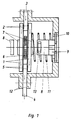
- FIG. 1 shows the disconnector according to the invention, the two contact plates 1 being connected in parallel.
- the electrical connection to a connector 3 is established via contact lamellae 2.
- the electrical connection is made from the connector 4 via the contact lamellae 5 to the contact plates 1, so that the current path is established in the direction of the arrow and thus a contact bridge is formed.
- the winding 6 is excited via a capacitor discharge device (not shown), so that the two contact plates 1 are repelled very quickly in opposite directions in the axial direction until the iron disks 7 firmly connected to the contact plates 1 abut the permanent-magnet capture devices.
- the permanent magnetic capture device advantageously consists of a permanent magnet 8, which is provided with an unlocking winding 13 and is connected to the housing 12 via a damping buffer 9 and the damping disk 10.
- the winding 6 is arranged in a winding support which is arranged between the connecting pieces 3 and 4.
- the connectors 3 and 4 are advantageously cast together with the winding 6.
- the moving mass essentially the contact plate 1 and the iron disk 7 and part of the contact pressure spring 11, are braked via the damping buffer 9 and the damping disk 10.
- the contact pressure spring 11 is used with a suitable spring preload, which is selected so that on the one hand it ensures the necessary contact pressure force of the contact plate 1 when the disconnector is closed and on the other hand enables the iron disk 7 to be securely locked on the permanent magnet 8 when the disconnector is open.
- the contact pressure spring 11 is supported on the housing 12 which is screwed to the connecting pieces 3 and 4.
- the lock is released to close the circuit breaker by means of a short current surge into the unlocking winding 13, which is arranged within the permanent magnet 8, whereby the holding force of the permanent magnet 8 is partially compensated, so that the spring force of the contact pressure spring 11 moves the contact plate 1 again in the direction of the connecting pieces 3 and 4 and thus closes the disconnector again.
- the simple switching path creates a double opening distance.
- the contact plate does not require any stranded wires.
- the mode of operation is such that a capacitor discharge takes place via the windings 22 and 23 lying in series and thus the contact plates 1 are repelled, then are caught by the means described in FIG. 1 and remain securely locked.
- the winding 6 or the windings 22 and 23 are designed in a rectangular or circular shape in FIG. 1 and FIG.
- a reaction-free design of the disconnector is achieved by the counter-movement of the contact plates, i.e. that no forces can act externally.
- the contact separation takes place very quickly and without an unlocking mechanism. Locking in the open state takes place without mechanical locking parts and is therefore also very quick.
Abstract
Description
Die Erfindung betrifft einen Trennschalter für Schaltanlagen, insbesondere für Bahnstrom-Anlagen mit Kommutierungseinrichtungen.The invention relates to a disconnector for switchgear, in particular for traction current systems with commutation devices.
Die bekannten Leistungs- und Trennschalter, die für eine hohe Schaltgeschwindigkeit ausgelegt sind, arbeiten mit Federspeicherantrieb und komplizierten Speziallösungen für die Entriegelungsmechanismen. Für das angestrebte Anwendungsgebiet bei Bahnstromanlagen mit elektronischen Kommutierungseinrichtungen, bei denen eine schnelle Abtrennung eines havarierten Streckenabgangs und ggf. eine schnelle Wiedereinschaltung nötig sind, sind diese, abgesehen von ihrer Kompliziertheit, auch nicht schnell genug. Ein erheblicher Teil des gesamten Schaltvorganges muß nämlich bereits für die Entriegelung aufgewendet werden.The well-known circuit breakers and disconnectors, which are designed for a high switching speed, work with spring-loaded actuators and complicated special solutions for the unlocking mechanisms. Apart from their complexity, these are also not fast enough for the intended field of application in railway power systems with electronic commutation devices, in which a fast disconnection of a damaged route exit and possibly a fast restart are necessary. A considerable part of the entire switching process must already be used for unlocking.
Es sind auch mit elektrodynamischem Antrieb, sogenanntem Thomson-Antrieb, versehene Schalteinrichtungen für Selbstschalter und Strombegrenzungsschalter mit gesonderter Antriebseinrichtung, Kontaktanordnung und gesonderter Einschalteinrichtung bekannt, siehe z.B. DE-A 36 42 283. Der Thomson-Antrieb arbeitet mit einer Spule und einer gegenüberliegenden Scheibe aus leitfähigem Material, in der bei Erregung der Spule, z.B. durch eine Kondensatorentladung, ein Strom induziert wird. Die gegeneinandergerichteten Ströme bewirken eine Kraft auf die Scheibe, die mit einem Kontakt in Verbindung steht. Die Kraftwirkung erfolgt sehr schnell. Auf einen gesonderten Entriegelungsmechanismus kann ggf. verzichtet werden.Switching devices for self-switches and current limiting switches with a separate drive device, contact arrangement and separate switch-on device are also known with an electrodynamic drive, so-called Thomson drive, see e.g. DE-A 36 42 283. The Thomson drive works with a coil and an opposite disc made of conductive material, in which when the coil is excited, e.g. through a capacitor discharge, a current is induced. The opposing currents exert a force on the disk which is connected to a contact. The force is very quick. A separate unlocking mechanism may be dispensed with.
Abgesehen davon, daß bei diesen bekannten Schalteinrichtungen viele Bauteile notwendig sind, sind sie von ihrem Aufbau her für den angegebenen Zweck, z.B. für eine schnelle Wiedereinschaltung, noch nicht geeignet.Apart from the fact that many components are necessary in these known switching devices, their structure is not yet suitable for the stated purpose, for example for a quick reclosure.
Der Erfindung liegt die Aufgabe zugrunde, einen schnellen Trennschalter mit geringer bewegter Masse, ohne Entriegelungssystem beim Auftrennen sowie einer möglichst verschleißfreien und sehr schnellen Verriegelungseinrichtung nach dem Auftrennen zu realisieren.The invention is based on the object of realizing a fast disconnector with a low moving mass, without an unlocking system when disconnecting, and a locking device which is as wear-free and very fast as possible after the disconnection.
Erfindungsgemäß wird die Aufgabe durch einen Trennschalter mit folgenden Merkmalen gelöst:
- durch die Erregung einer Wicklung, z.B. durch eine Kondensatorentladung, werden zwei leichte Kontaktplatten, die jeweils einer Spulenseite gegenüberliegend angeordnet sind, in Gegenrichtung gegen die Kraft jeweils einer Kontaktanpreßfeder abgestoßen,
- jede Kontaktplatte trägt eine Eisenscheibe, die gegen eine Einfangeinrichtung mit einem Permanentmagneten anläuft und die dämpfendorweise die Eisenscheibe mitsamt der Kontaktplatte und die Kontaktanpreßfeder verriegelt,
- diese Verriegelung kann mittels eines Stromstoßes in eine induktivitätsarme Entriegelungswicklung aufgehoben werden.
- by exciting a winding, for example by a capacitor discharge, two light contact plates, which are each arranged opposite one coil side, are repelled in the opposite direction against the force of a contact pressure spring,
- Each contact plate carries an iron disk, which runs against a capturing device with a permanent magnet and which locks the iron disk together with the contact plate and the contact pressure spring in a damping manner.
- this locking can be released by means of a current surge in a low-inductance unlocking winding.
Im Falle einer sofortigen, sehr schnellen Rückbewegung der Kontaktplatte ist die Einfangeinrichtung somit bereits wieder voll arbeitsfähig, um die bewegten Teile sicher zu arretieren.In the event of an immediate, very rapid return movement of the contact plate, the catching device is thus fully operational again in order to securely lock the moving parts.
Weitere ausgestaltende Merkmale sind den Unteransprüchen zu entnehmen.Further design features can be found in the subclaims.
Die Erfindung soll nachstehend an zwei Ausführungsbeispielen erläutert werden. In den zugehörigen Zeichnungen zeigen
- Fig.1
- eine Prinzipdarstellung des erfindungsgemäßen Trennschalters mit der Parallelschaltung von zwei Kontaktplatten, die ohne Anschlußlitzen ausgeführt werden können,
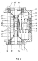
- Fig.2
- den Trennschalter mit der Reihenschaltung von zwei Kontaktplatten, die mit Anschlußlitzen ausgeführt sind.
- Fig. 1
- 2 shows a basic illustration of the disconnector according to the invention with the parallel connection of two contact plates, which can be implemented without connecting leads,
- Fig. 2
- the disconnector with the series connection of two contact plates, which are designed with connecting leads.
Fig.1 zeigt den erfindungsgemäßen Trennschalter, wobei die beiden Kontaktplatten 1 parallel geschaltet sind. Über Kontaktlamellen 2 wird die elektrische Verbindung zu einem Anschlußstück 3 hergestellt. In gleicher Weise wird die elektrische Verbindung vom Anschlußstück 4 über die Kontaktlamellen 5 zu den Kontaktplatten 1 hergestellt, so daß der Stromweg in der gekennzeichneten Pfeilrichtung hergestellt und somit eine Kontaktbrücke gebildet ist. Über eine nicht dargestellte Kondensatorentladeeinrichtung wird die Wicklung 6 erregt, so daß die beiden Kontaktplatten 1 in axialer Richtung sehr schnell gegenläufig abgestoßen werden, bis die mit den Kontaktplatten 1 fest verbundenen Eisenscheiben 7 an den permanentmagnetischen Einfangeinrichtungen anstoßen. Die permanentmagnetische Einfangeinrichtung besteht vorteilhafterweise aus einem Permanentmagneten 8, der mit einer Entriegelungswicklung 13 versehen ist und über einen Dämpfungspuffer 9 sowie die Dämpfungsscheibe 10 mit dem Gehäuse 12 verbunden ist. Die Wicklung 6 ist in einem Wicklungsträger angeordnet, der zwischen den Anschlußstücken 3 und 4 angeordnet ist. Vorteilhaft werden die Anschlußstücken 3 und 4 zusammen mit der Wicklung 6 vergossen.1 shows the disconnector according to the invention, the two
Über die Dämpfungspuffer 9 und die Dämpfungsscheibe 10 wird die sich bewegende Masse, im wesentlichen die Kontaktplatte 1 und die Eisenscheibe 7 und ein Teil der Kontaktandruckfeder 11, abgebremst. Die Kontaktandruckfeder 11 wird mit einer geeigneten Federvorspannung eingesetzt, die so gewählt ist, daß sie einerseits die notwendige Kontaktanpreßkraft der Kontaktplatte 1 bei geschlossenem Trennschalter gewährleistet und andererseits eine sichere Arretierung der Eisenscheibe 7 am Permanentmagneten 8 bei geöffnetem Trennschalter ermöglicht. Die Kontaktanpreßfeder 11 stützt sich dabei auf das Gehäuse 12 ab, welches mit den Anschlußstücken 3 und 4 fest verschraubt ist. Das Freimachen der Verriegelung zum Schließen des Trennschalters erfolgt über einen kurzen Stromstoß in die Entriegelungswicklung 13, die innerhalb des Permanentmagneten 8 angeordnet ist, wodurch die Haltekraft des Permanentmagneten 8 teilweise kompensiert wird, so daß die Federkraft der Kontaktandruckfeder 11 die Kontaktplatte 1 wieder in Richtung der Anschlußstücke 3 und 4 bewegt und somit den Trennschalter wieder schließt.The moving mass, essentially the
Bei der Öffnung der Kontaktstellen entsteht durch den einfachen Schaltweg eine zweifache Öffnungsstrecke. Die Kontaktplatte benötigt bei dieser Variante keine Anschlußlitzen.When the contact points open, the simple switching path creates a double opening distance. In this variant, the contact plate does not require any stranded wires.
Fig.2 zeigt eine Variante der Anordnung mit der Reihenschaltung der zwei Kontaktplatten 1, wobei die elektrische Verbindung über die Anschlußlitzen 14, 16 zu den Anschlußringen 15, 17 hergestellt wird, die ihrerseits fest mit den Anschlußstücken 3, 4 verbunden sind. Somit ergibt sich, bei geschlossenem Trennschalter, ein Stromweg vom Anschlußstück 3 zum Anschlußring 17 durch die Anschlußlitzen 16 zur ersten Kontaktplatte 1, über die Kontaktlamellen 18, durch das Leitstück 19 zu den anderen Kontaktlamellen 20, zur zweiten Kontaktplatte 1 und über die Anschlußlitzen 14, den Anschlußring 15 hin zum Anschlußstück 4 . Das Leitstück 19 ist eingelagert in einen Wicklungsträger 21, der die beiden scheibenförmigen Wicklungen 22 und 23 trägt.2 shows a variant of the arrangement with the series connection of the two
Die Wirkungsweise ist derart, daß eine Kondensatorentladung über die in Reihe liegenden Wicklungen 22 und 23 erfolgt und somit die Kontaktplatten 1 abgestoßen werden, dann mit den zu Fig.1 beschriebenen Mitteln eingefangen werden und sicher arretiert bleiben. Auch bei dieser Ausführungsform ergibt sich im Trennschalter bei einem einfachen Schaltweg eine zweifache Öffnungsstrecke.The mode of operation is such that a capacitor discharge takes place via the
Je nach der notwendigen Größe und Anordnung der Kontaktflächen sind in Fig.1 und Fig.2 die Wicklung 6 bzw. die Wicklungen 22 und 23 in Rechteck- oder Kreisform ausgeführt.Depending on the necessary size and arrangement of the contact surfaces, the winding 6 or the
Bei beiden Varianten wird ein reaktionsfreier Aufbau des Trennschalters durch die gegenläufige Bewegung der Kontaktplatten realisiert, d.h. daß nach außen keine Kräfte wirksam werden können. Die Kontakttrennung erfolgt sehr schnell und ohne einen Entriegelungsmechanismus. Die Verriegelung im geöffneten Zustand erfolgt ohne mechanische Verriegelungsteile und ist deshalb ebenfalls sehr schnell.In both versions, a reaction-free design of the disconnector is achieved by the counter-movement of the contact plates, i.e. that no forces can act externally. The contact separation takes place very quickly and without an unlocking mechanism. Locking in the open state takes place without mechanical locking parts and is therefore also very quick.
Claims (9)
- Disconnector with high operating speed, where operation is effected by the Thomson principle, characterized by the following features:- two axially moving contact plates (1) arranged opposite one another, each of which bears a magnetically permeable disk (7), are each pressed by a contact pressure spring (11) onto a contact-establishing member which,- the contact-making member bears a winding (6 and 22, 23) by means of whose energization the contact plates (1) are moved away from one another,- the movement of the contact plates (1) takes place in opposition to a permanently-magnetic capture device which is provided with a release winding (13).
- Disconnector in accordance with Claim 1, characterized by the fact that excitation of the winding (6 and 22,23) is effected by means of a capacitor discharge.
- Disconnector in accordance with Claim 1, characterized by the fact that the contact-establishing member consists of the connectors (3, 4) of the disconnector with a holder for the winding (6) interposed between them.
- Disconnector in accordance with Claim 1, characterized by the fact that the contact-establishing member consists of a holder for the windings (22,23) with a centrally arranged conductive connecting element.
- Disconnector in accordance with Claim 1, characterized by the fact that the winding (6) is encapsulated together with the connectors (3, 4).
- Disconnector in accordance with Claim 1, characterized by the fact that the contact pressure springs (11) are supported on the housing (12).
- Disconnector in accordance with Claim 1, characterized by the fact that the permanently-magnetic capture device is provided with an elastic damping pad (9).
- Disconnector in accordance with Claim 1 or 7, characterized by the fact that the permanently-magnetic capture device is supported on the housing (12) by means of a damping disk (10).
- Disconnector in accordance with Claim 1, characterized by the fact that the contact plates (1) are joined to the contact-establishing member via contact laminations (2, 5 and 18, 20).
Applications Claiming Priority (2)
| Application Number | Priority Date | Filing Date | Title |
|---|---|---|---|
| DE4209199 | 1992-03-19 | ||
| DE4209199A DE4209199C2 (en) | 1992-03-19 | 1992-03-19 | Disconnector with high switching speed |
Publications (2)
| Publication Number | Publication Date |
|---|---|
| EP0561485A1 EP0561485A1 (en) | 1993-09-22 |
| EP0561485B1 true EP0561485B1 (en) | 1995-12-20 |
Family
ID=6454674
Family Applications (1)
| Application Number | Title | Priority Date | Filing Date |
|---|---|---|---|
| EP93250082A Expired - Lifetime EP0561485B1 (en) | 1992-03-19 | 1993-03-12 | High speed disconnecting switch |
Country Status (3)
| Country | Link |
|---|---|
| EP (1) | EP0561485B1 (en) |
| AT (1) | ATE131955T1 (en) |
| DE (2) | DE4209199C2 (en) |
Cited By (2)
| Publication number | Priority date | Publication date | Assignee | Title |
|---|---|---|---|---|
| DE10058419C1 (en) * | 2000-11-24 | 2002-06-06 | Moeller Gmbh | Current-limiting switch has conductor loop provided with switching current providing electrodynamic forces assisting opening movement of contact device upon overload detection |
| CN104810209A (en) * | 2014-01-28 | 2015-07-29 | Ls产电株式会社 | Relay |
Families Citing this family (2)
| Publication number | Priority date | Publication date | Assignee | Title |
|---|---|---|---|---|
| DE19740490C1 (en) * | 1997-09-15 | 1999-04-15 | Condor Werke Gebr Frede Gmbh & | Isolating switch for interrupting the current in a conductor in the event of a short circuit or excessive current |
| DE19851226C2 (en) * | 1998-11-06 | 2002-04-11 | Condor Werke Gebr Frede Gmbh & | disconnectors |
Family Cites Families (6)
| Publication number | Priority date | Publication date | Assignee | Title |
|---|---|---|---|---|
| DE1071821B (en) * | 1955-04-06 | 1959-12-24 | ||
| DE1091207B (en) * | 1957-07-12 | 1960-10-20 | Siemens Ag | Electrodynamic drive system, especially for electrical switches |
| GB1068324A (en) * | 1963-05-20 | 1967-05-10 | John Henry Waghorne | Electric circuit breaker |
| CA916207A (en) * | 1970-09-08 | 1972-12-05 | Zajic Vladislav | Disjoncteur pour courant continu a tres haute tension |
| GB2150352A (en) * | 1983-11-25 | 1985-06-26 | Electricity Council | Circuit breaker assembly |
| DE3642383A1 (en) * | 1986-12-12 | 1988-06-16 | Siemens Ag | Current-limiting switch |
-
1992
- 1992-03-19 DE DE4209199A patent/DE4209199C2/en not_active Expired - Fee Related
-
1993
- 1993-03-12 DE DE59301186T patent/DE59301186D1/en not_active Expired - Fee Related
- 1993-03-12 AT AT93250082T patent/ATE131955T1/en not_active IP Right Cessation
- 1993-03-12 EP EP93250082A patent/EP0561485B1/en not_active Expired - Lifetime
Cited By (2)
| Publication number | Priority date | Publication date | Assignee | Title |
|---|---|---|---|---|
| DE10058419C1 (en) * | 2000-11-24 | 2002-06-06 | Moeller Gmbh | Current-limiting switch has conductor loop provided with switching current providing electrodynamic forces assisting opening movement of contact device upon overload detection |
| CN104810209A (en) * | 2014-01-28 | 2015-07-29 | Ls产电株式会社 | Relay |
Also Published As
| Publication number | Publication date |
|---|---|
| EP0561485A1 (en) | 1993-09-22 |
| ATE131955T1 (en) | 1996-01-15 |
| DE4209199C2 (en) | 1997-02-06 |
| DE59301186D1 (en) | 1996-02-01 |
| DE4209199A1 (en) | 1993-09-23 |
Similar Documents
| Publication | Publication Date | Title |
|---|---|---|
| DE102011118418B4 (en) | switching system | |
| EP2463877A1 (en) | Switch with arcing chamber | |
| EP2463878A1 (en) | Switch with arcing chamber | |
| DE112005002227T5 (en) | Electric contactors | |
| DE19515322C2 (en) | Drive device with an electric motor and a relay that switches the motor current | |
| EP0898780A1 (en) | Magnetically driven electric switch | |
| DE3302884A1 (en) | ELECTRIC CIRCUIT BREAKER | |
| EP0561485B1 (en) | High speed disconnecting switch | |
| DE2948959A1 (en) | CIRCUIT ARRANGEMENT FOR ACTUATING ELECTROMAGNETIC SWITCHGEAR | |
| EP1132929A1 (en) | Permanent magnetic drive for an electrical switching device | |
| EP0007429A1 (en) | Low voltage electrical circuit breaker | |
| EP1671344B1 (en) | Method for increasing current load capacity and for accelerating dynamic contact opening of power switches and associated switching device | |
| DE2609708C2 (en) | Miniature circuit breaker with arc starting aid | |
| DE10140559A1 (en) | Electromagnet arrangement for a switch | |
| DE10132858B4 (en) | breaker | |
| DE3129161A1 (en) | Arc extinguishing chamber | |
| DE19740490C1 (en) | Isolating switch for interrupting the current in a conductor in the event of a short circuit or excessive current | |
| EP1180776A1 (en) | Fast mechanical switch | |
| DE2356515C2 (en) | Electrodynamic switching device such as relay, contactor or the like. | |
| EP0113836A2 (en) | Brush wear controlling device | |
| DE19957228B4 (en) | Contact arrangement for a vacuum interrupter chamber | |
| DE2215180A1 (en) | Electromagnetic switching device | |
| EP0736887B1 (en) | Electrical contact assembly | |
| EP0410258B1 (en) | Electromechanic high-speed breaker | |
| DE2358382B2 (en) | Overcurrent switching device with two interruption points connected in series |
Legal Events
| Date | Code | Title | Description |
|---|---|---|---|
| PUAI | Public reference made under article 153(3) epc to a published international application that has entered the european phase |
Free format text: ORIGINAL CODE: 0009012 |
|
| AK | Designated contracting states |
Kind code of ref document: A1 Designated state(s): AT BE DE DK ES FR IT NL SE |
|
| 17P | Request for examination filed |
Effective date: 19940107 |
|
| 17Q | First examination report despatched |
Effective date: 19950512 |
|
| GRAA | (expected) grant |
Free format text: ORIGINAL CODE: 0009210 |
|
| AK | Designated contracting states |
Kind code of ref document: B1 Designated state(s): AT BE DE DK ES FR IT NL SE |
|
| PG25 | Lapsed in a contracting state [announced via postgrant information from national office to epo] |
Ref country code: IT Free format text: LAPSE BECAUSE OF FAILURE TO SUBMIT A TRANSLATION OF THE DESCRIPTION OR TO PAY THE FEE WITHIN THE PRE;WARNING: LAPSES OF ITALIAN PATENTS WITH EFFECTIVE DATE BEFORE 2007 MAY HAVE OCCURRED AT ANY TIME BEFORE 2007. THE CORRECT EFFECTIVE DATE MAY BE DIFFERENT FROM THE ONE RECORDED.SCRIBED TIME-LIMIT Effective date: 19951220 Ref country code: ES Free format text: THE PATENT HAS BEEN ANNULLED BY A DECISION OF A NATIONAL AUTHORITY Effective date: 19951220 Ref country code: DK Effective date: 19951220 |
|
| REF | Corresponds to: |
Ref document number: 131955 Country of ref document: AT Date of ref document: 19960115 Kind code of ref document: T |
|
| REF | Corresponds to: |
Ref document number: 59301186 Country of ref document: DE Date of ref document: 19960201 |
|
| PG25 | Lapsed in a contracting state [announced via postgrant information from national office to epo] |
Ref country code: SE Effective date: 19960320 |
|
| ET | Fr: translation filed | ||
| PLBE | No opposition filed within time limit |
Free format text: ORIGINAL CODE: 0009261 |
|
| STAA | Information on the status of an ep patent application or granted ep patent |
Free format text: STATUS: NO OPPOSITION FILED WITHIN TIME LIMIT |
|
| 26N | No opposition filed | ||
| NLS | Nl: assignments of ep-patents |
Owner name: ELPRO BAHNSTROMANLAGEN GMBH |
|
| PGFP | Annual fee paid to national office [announced via postgrant information from national office to epo] |
Ref country code: BE Payment date: 19990308 Year of fee payment: 7 |
|
| PGFP | Annual fee paid to national office [announced via postgrant information from national office to epo] |
Ref country code: AT Payment date: 19990324 Year of fee payment: 7 |
|
| PGFP | Annual fee paid to national office [announced via postgrant information from national office to epo] |
Ref country code: FR Payment date: 19990330 Year of fee payment: 7 |
|
| REG | Reference to a national code |
Ref country code: FR Ref legal event code: TP |
|
| PGFP | Annual fee paid to national office [announced via postgrant information from national office to epo] |
Ref country code: NL Payment date: 19991216 Year of fee payment: 8 |
|
| PG25 | Lapsed in a contracting state [announced via postgrant information from national office to epo] |
Ref country code: AT Free format text: LAPSE BECAUSE OF NON-PAYMENT OF DUE FEES Effective date: 20000312 |
|
| PG25 | Lapsed in a contracting state [announced via postgrant information from national office to epo] |
Ref country code: BE Free format text: LAPSE BECAUSE OF NON-PAYMENT OF DUE FEES Effective date: 20000331 |
|
| BERE | Be: lapsed |
Owner name: ELPRO BAHNSTROMANLAGEN G.M.B.H. Effective date: 20000331 |
|
| PG25 | Lapsed in a contracting state [announced via postgrant information from national office to epo] |
Ref country code: FR Free format text: LAPSE BECAUSE OF NON-PAYMENT OF DUE FEES Effective date: 20001130 |
|
| REG | Reference to a national code |
Ref country code: FR Ref legal event code: ST |
|
| PG25 | Lapsed in a contracting state [announced via postgrant information from national office to epo] |
Ref country code: NL Free format text: LAPSE BECAUSE OF NON-PAYMENT OF DUE FEES Effective date: 20011001 |
|
| NLV4 | Nl: lapsed or anulled due to non-payment of the annual fee |
Effective date: 20011001 |
|
| PGFP | Annual fee paid to national office [announced via postgrant information from national office to epo] |
Ref country code: DE Payment date: 20050922 Year of fee payment: 13 |
|
| PG25 | Lapsed in a contracting state [announced via postgrant information from national office to epo] |
Ref country code: DE Free format text: LAPSE BECAUSE OF NON-PAYMENT OF DUE FEES Effective date: 20061003 |