EP0560779B1 - Method of detecting and estimating the position in space of objects from a two-dimensional image - Google Patents
Method of detecting and estimating the position in space of objects from a two-dimensional image Download PDFInfo
- Publication number
- EP0560779B1 EP0560779B1 EP91917369A EP91917369A EP0560779B1 EP 0560779 B1 EP0560779 B1 EP 0560779B1 EP 91917369 A EP91917369 A EP 91917369A EP 91917369 A EP91917369 A EP 91917369A EP 0560779 B1 EP0560779 B1 EP 0560779B1
- Authority
- EP
- European Patent Office
- Prior art keywords
- position parameters
- grid
- neuron
- output values
- dimensional
- Prior art date
- Legal status (The legal status is an assumption and is not a legal conclusion. Google has not performed a legal analysis and makes no representation as to the accuracy of the status listed.)
- Expired - Lifetime
Links
Images


Classifications
-
- G—PHYSICS
- G06—COMPUTING; CALCULATING OR COUNTING
- G06T—IMAGE DATA PROCESSING OR GENERATION, IN GENERAL
- G06T7/00—Image analysis
- G06T7/50—Depth or shape recovery
-
- G—PHYSICS
- G06—COMPUTING; CALCULATING OR COUNTING
- G06F—ELECTRIC DIGITAL DATA PROCESSING
- G06F18/00—Pattern recognition
- G06F18/20—Analysing
- G06F18/21—Design or setup of recognition systems or techniques; Extraction of features in feature space; Blind source separation
- G06F18/213—Feature extraction, e.g. by transforming the feature space; Summarisation; Mappings, e.g. subspace methods
- G06F18/2137—Feature extraction, e.g. by transforming the feature space; Summarisation; Mappings, e.g. subspace methods based on criteria of topology preservation, e.g. multidimensional scaling or self-organising maps
-
- G—PHYSICS
- G06—COMPUTING; CALCULATING OR COUNTING
- G06V—IMAGE OR VIDEO RECOGNITION OR UNDERSTANDING
- G06V10/00—Arrangements for image or video recognition or understanding
- G06V10/20—Image preprocessing
- G06V10/24—Aligning, centring, orientation detection or correction of the image
-
- G—PHYSICS
- G06—COMPUTING; CALCULATING OR COUNTING
- G06V—IMAGE OR VIDEO RECOGNITION OR UNDERSTANDING
- G06V20/00—Scenes; Scene-specific elements
- G06V20/60—Type of objects
- G06V20/64—Three-dimensional objects
-
- G—PHYSICS
- G06—COMPUTING; CALCULATING OR COUNTING
- G06T—IMAGE DATA PROCESSING OR GENERATION, IN GENERAL
- G06T2207/00—Indexing scheme for image analysis or image enhancement
- G06T2207/20—Special algorithmic details
- G06T2207/20084—Artificial neural networks [ANN]
Definitions
- the visual representation of the room in the image plane can be approximated with sufficient accuracy, for example by the central projection.
- the technical problem in recognizing and estimating the position parameters of three-dimensional objects in space from a two-dimensional image often also referred to as an n-point perspective problem, consists in determining the position and spatial arrangement of a three-dimensional object from n feature points using suitable preprocessing methods were found in a two-dimensional image of the object to be recognized. Examples of such feature points include images of object corner points or images of other prominent points on the object surface.
- a second type of procedure uses the iterative solution of over-determined systems of equations with the help of nonlinear minimization procedures. This minimizes a cost function, which is determined by previously found correspondence between image features and model parameters.
- An example of this second type of method is in the publication by DG Lowe "Three-Dimensional Object Recognition from Single Two-Dimensional Images", Artificial Intelligence 31, 1987, pp. 355-395. While this second type of process is far less sensitive to interference, it does like the first type of process the disadvantage that a nonlinear analytical model of the optical imaging process is required and must be processed with numerical methods.
- the method according to the invention is based on the method of adaptive vector quantization, which can also be referred to as so-called
- Kohonen network can be formulated (T. Kohonen, "Representation of Sensory Information in Self-Organizing Feature Maps, and Relation of these Maps to Distributed Memory Networks", Proc. SPIE Optical and Hybrid computing, vol. 634, pp. 248- 259, 1986).
- pattern vectors are formed from the two-dimensional coordinates of feature points in the imaging plane, which are compared with stored reference patterns, which are also referred to as weight coefficients in the language of the Kohonen networks.
- An interpretation is assigned to each reference pattern, which leads directly to the position parameters of the object to be recognized as well as the object identity.
- the sought-after location parameters or the sought-after object identifier are obtained as an interpretation of the reference pattern that is most similar to the pattern vector representing the feature points of the imaging plane.
- reference patterns represent the statistical distribution of the training patterns, and the structural properties of the objects to be recognized as well as the structural properties of the optical imaging process are coded in the assignment between reference patterns and interpretations.
- FIG. 1 shows a cuboid with corner points 1, 2, ..., 7 projected into the imaging plane and the two-dimensional coordinates q (1), ..., p (3) belonging to corner points 1 and 3, respectively.
- FIG. 2 shows a flowchart of the method for position estimation or for object detection with simultaneous position estimation.
- FIG. 3 shows a flowchart of the method for adapting reference patterns for estimating position parameters or for object detection with simultaneous estimation of position parameters.
- two-dimensional images of three-dimensional objects are generated using electronic cameras.
- an optical image the three-dimensional space is projected into a two-dimensional image plane.
- the structural properties of this optical imaging process depend on the optical properties of the camera used and can generally be described with sufficient accuracy by the mathematical model of the central projection (also called perspective projection).
- the electronic camera is a two-dimensional image of the three-dimensional object, which is available in a digital image memory.
- FIG. 1 shows a three-dimensional cuboid with visible corner points 1, 2,..., 7 projected into the two-dimensional image plane whose coordinate axes are denoted by q or p. If the corner points of the cuboid are found in the image plane using suitable methods of digital image preprocessing so their two-dimensional coordinates are available for position estimation or object detection. An overview of the available methods for feature extraction can be found in (Y. Shirai 1987). Images of object corner points are primarily suitable as feature points.
- the solution to this problem according to the invention uses the method of adaptive vector quantization, which is also referred to as a Kohonen network. Since this is an adaptive method, the technical application of this method requires a suitable learning process. Such a learning method is therefore described below with reference to FIG. 3.
- a spatial grid of neurons is required to carry out this learning process, i.e. an entirety RG of reference patterns m (i) which can be indexed by integers, each index i of the entirety reversibly uniquely a grid point (i (l), i (2), i (3)) with integers i (l), i (2) and i (3) is assigned. Every neuron, i.e.
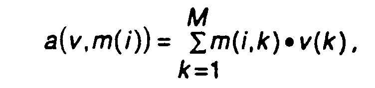
- each element i of the entirety assigns its reference pattern m (i) to an output value a (v, m (i)) belonging to it with the aid of an output function a (v, m) that is the same for all neurons.
- the values of all reference patterns m (i) are chosen completely randomly.
- an interpretation x (i) (x (i, l), ..., x (i, N)) is assigned to each neuror i.
- the values of the components of all interpretations x (i) are also chosen completely at random.
- the components of the interpretations x (i) correspond to the location parameters of the depicted object to be estimated.
- a time-dependent learning rate L (t) is specified, which falls monotonically over time. This learning rate determines the speed of the learning process and becomes smaller the further the learning process has progressed.
- L (start), L (end) and t (end) denote a predefined initial learning rate, a predefined final learning rate or an end time of the learning process.
- a coupling strength function h (i, j, t) is specified, which has two points (i (1), i (2), i (3)), (j (1), j (2), j (3) ) assigns a coupling strength h on the grid, which falls monotonically with the distance between the grid points and monotonically with time.
- 2nd 2nd s 2nd t ) With (4) s (t) s (start).
- This choice of coupling strength function ensures that the coupling strength between two neurons decreases monotonically with the distance between these neurons, and that the coupling strength decreases monotonically with time for a given distance. As a result, the coupling between neighboring neurons on the lattice becomes increasingly short-range over time and weaker at a given distance.
- the Euclidean distance is preferably selected as the distance measure between the neurons.
- the adaptation relationships (5) and (6) ensure that the value distribution of the reference patterns becomes more and more similar to the statistical distribution of the training pattern vectors in the course of the learning process, and that the relationships between pattern vectors and position parameters corresponding to the training pattern vectors and their associated position parameters become apparent during the course of the learning process the adaptation-adjusting relationship between the position parameters of the neurons and the associated reference patterns is reflected.
- the choice of a suitable output function a (v, m) is crucial.
- Various experimental studies have shown that there are mainly two different ones possible choices of the output function a (v, m) lead to an optimal efficiency of the procedure.
- the first possible choice is the square of the Euclidean distance between the pattern vector and the reference pattern vector of a neuron,
- the optimal output value is the maximum output value.
- the trained neural network (or in other words, the adapted set of reference patterns) can be used to estimate the position three-dimensional objects.
- feature points are extracted from a given two-dimensional image of the three-dimensional object using the previously described methods for pre-processing digital images (Y. Sirai 1987) and the two-dimensional coordinates of these feature points are combined to form a pattern vector v.
- the output value a (i) a (v, m (i)) is now calculated according to FIG. 2 for each index i of the entirety of neurons.
- the index w of the neuron which has provided the optimal output value a (w) is then sought.
- the components of the interpretation x (w) of this neuron with the index w can now be regarded as the optimal estimate of the position parameters of the object represented by the pattern vector v.
- an interpolated interpretation is used to estimate the position.
- Such an interpolated interpretation can be calculated as follows:
- One of the two forms given in equations (7) and (8) is preferably used again as the output function. Due to the simple analytical form of the described output functions, an optimal value of the output function parameterized by b can be sought in a closed manner as a function of b. This optimal value of b is designated b (u) for each neuron u in the environment. This results in a numerical value b (u) between 0 and 1 and an associated interpolated reference pattern m (w, u, b (u)) for all neurons in the environment.
- the optimal interpolated reference pattern is now found among these interpolated reference patterns by the fact that for all interpolated reference patterns m (w, u, b, (u)) of all neurons u in the environment the associated output values a (v, m (w, u, b ( u))) can be calculated.
- the convex linear combination is formed from all reference patterns m (u) with u from a given environment U of b With and (15) 0 ⁇ b (u), b (w) ⁇ 1.
- the method described here can still be used successfully if not only the spatial position and orientation of a known object is to be estimated, but also if the identity of an a priori unknown object, which is taken from a known set of objects, is simultaneous to determine the position and orientation of this object in space.
- a further component which corresponds to the object identifier, must be added to the components of the interpretations corresponding to the position parameters to be estimated.
- each training pattern vector is then accompanied by those belonging to this training pattern vector Position parameters to specify the relevant object identifier. After the learning process carried out in this way, the neural network is thus able to determine the object identity in addition to the unknown location parameters.
Abstract
Description
Bei den meisten Anwendungen der maschinellen Bildverarbeitung und des Bildverstehens in Anwendungsgebieten wie Robotik und Fertigungsautomatisierung, sind Verfahren zur maschinellen Erkennung dreidimensionaler Objekte und ihrer Lage im Raum von grundlegender Bedeutung. In vielen dieser Anwendungsfälle stehen Tiefendaten nicht zur Verfügung und sind auch nicht mit Hilfe von Stereobildern oder zeitlichen Bildfolgen, in denen die Objektbewegung oder die Kamerabewegung zur Gewinnung von Tiefendaten ausgewertet werden könnte, zu ermitteln. In solchen Fällen muß anhand einer einzelnen zweidimensionalen Abbildung des zu erkennenden Objektes die Objektidentität und seine Lage im Raum aus der zweidimensionalen Abbildung rekonstruiert werden. Hierzu müssen im allgemeinen Modelle für die zu erkennenden Objekte und ein Modell für den Abbildungsprozeß verwendet werden. Aus Vereinfachungsgründen werden Objekte vielfach mit Hilfe ihrer Eckpunkte und Kantenlinien modelliert. Die optische Abbildung des Raumes in die Bildebene kann in vielen Fällen mit hinreichender Genauigkeit z.B. durch die Zentralprojektion angenähert werden. Das technische Problem bei der Erkennung und Schätzung der Lageparameter dreidimensionaler Objekte im Raum aus einer zweidimensionalen Abbildung, oftmals auch als n-Punkte-Perspektivproblem bezeichnet, besteht in der Bestimmung der Lage und räumlichen Anordnung eines dreidimensionalen Objekts aus n Merkmalspunkten, die mit Hilfe geeigneter Vorverarbeitungsverfahren in einer zweidimensionalen Abbildung des zu erkennenden Objekts gefunden wurden. Beispiele für solche Merkmalspunkte sind u.a. Abbilder von Objekteckpunkten oder Abbilder von anderen markanten Punkten auf der Objektoberfläche.For most applications of machine vision and image understanding in application areas such as robotics and manufacturing automation, methods for machine detection of three-dimensional objects and their position in space are of fundamental importance. In many of these applications, depth data are not available and cannot be determined with the aid of stereo images or temporal image sequences in which the object movement or the camera movement could be evaluated to obtain depth data. In such cases, the object identity and its position in space must be reconstructed from the two-dimensional image on the basis of a single two-dimensional image of the object to be recognized. For this purpose, models for the objects to be recognized and a model for the imaging process must generally be used. For reasons of simplification, objects are often modeled using their corner points and edge lines. In many cases, the visual representation of the room in the image plane can be approximated with sufficient accuracy, for example by the central projection. The technical problem in recognizing and estimating the position parameters of three-dimensional objects in space from a two-dimensional image, often also referred to as an n-point perspective problem, consists in determining the position and spatial arrangement of a three-dimensional object from n feature points using suitable preprocessing methods were found in a two-dimensional image of the object to be recognized. Examples of such feature points include images of object corner points or images of other prominent points on the object surface.
Aus der Literatur sind verschiedene Verfahren zur Lageschätzung dreidimensionaler Objekte im Raum bekannt. Im wesentlichen lassen sich zwei Typen von Verfahren unterscheiden: Zum einen gibt es Ansätze zur analytischen Lösung des n-Punkte-Perspektivproblems, die sich mit der minimalen Anzahl von Korrespondenzen beschäftigen, welche man benötigt, um das Perspektivproblem starrer Objekte, d.h. das Problem der Zuordnung zwischen Objekteckpunkten und Merkmalspunkten in der Bildebene, zu lösen. Bei diesen Verfahrenstypen wird der die Abbildung modellierende Zusammenhang zwischen Punkten im Raum und Punkten in der Bildebene, z. B die Zentralprojektion, zur Aufstellung eines Gleichungssystems verwendet. Je nach der Zahl der Merkmalspunkte in der Bildebene kann dieses Gleichungssystem unterbestimmt, eindeutig lösbar, oder überbestimmt sein. Diese Verfahren verwenden deshalb im allgemeinen eine Teilmenge aller verfügbaren Merkmalspunkte in der Bildebene, welche auf ein eindeutig lösbares und gut konditioniertes Gleichungssystem führen. Ein derartiges Verfahren wird z.B. in der Veröffentlichung von R.M. Haralick, "Using Perspective Transformations in Scene Analysis", Computer Vision, Graphics and Image Processing 13, 1980, pp. 191-221, beschrieben. Verfahren dieses Typs führen im allgemeinen zu über- oder unterbestimmten Gleichungssystemen, erfordern deshalb eine Vorverarbeitung der Abbildung mit dem Ziel der Auswahl einer geeigneten Menge von Merkmalspunkten, und sind im allgemeinen wenig robust gegen Störungen.Various methods for estimating the position of three-dimensional objects in space are known from the literature. Essentially, two types of methods can be distinguished: First, there are approaches for the analytical solution of the n-point perspective problem, which deal with the minimal number of correspondences required to solve the perspective problem of rigid objects, i.e. to solve the problem of the assignment between object corner points and feature points in the image plane. In these types of processes, the relationship between the points modeling in space and points in the image plane, e.g. B the central projection used to set up a system of equations. Depending on the number of feature points in the image plane, this system of equations can be under-determined, uniquely solvable, or over-determined. These methods therefore generally use a subset of all available feature points in the image plane, which lead to a clearly solvable and well-conditioned system of equations. Such a method is e.g. in the publication by R.M. Haralick, "Using Perspective Transformations in Scene Analysis", Computer Vision, Graphics and Image Processing 13, 1980, pp. 191-221. Methods of this type generally lead to over- or under-determined systems of equations, therefore require preprocessing of the mapping with the aim of selecting a suitable set of feature points, and are generally not very robust against disturbances.
Ein zweiter Verfahrenstyp bedient sich der iterativen Lösung überbestimmter Gleichungssysteme mit Hilfe von nichtlinearen Minimierungsverfahren. Dabei wird eine Kostenfunktion, welche durch zuvor gefundene Korrespondenzen zwischen Bildmerkmalen und Modellparametern bestimmt wird, minimiert. Ein Beispiel für diesen zweiten Verfahrenstyp ist in der Veröffentlichung von D.G. Lowe "Three-Dimensional Object Recognition from Single Two-Dimensional Images", Artificial Intelligence 31, 1987, pp. 355-395, beschrieben. Dieser zweite Verfahrenstyp ist zwar weitaus weniger empfindlich gegen Störungen, hat aber wie der erste Verfahrenstyp den Nachteil, daß ein nichtlineares analytisches Modell des optischen Abbildungsvorganges benötigt wird und mit numerischen Methoden verarbeitet werden muß.A second type of procedure uses the iterative solution of over-determined systems of equations with the help of nonlinear minimization procedures. This minimizes a cost function, which is determined by previously found correspondence between image features and model parameters. An example of this second type of method is in the publication by DG Lowe "Three-Dimensional Object Recognition from Single Two-Dimensional Images", Artificial Intelligence 31, 1987, pp. 355-395. While this second type of process is far less sensitive to interference, it does like the first type of process the disadvantage that a nonlinear analytical model of the optical imaging process is required and must be processed with numerical methods.
Wei-Chung Lin et al., "A Connectionist Approach to Multiple-View Based 3-D Object Recognition" (International Joint Conference on Neural Networks, IJCNN 1990), benutzen Hopfield-Neuronale Netze (mit gewöhnlicher, zweidimensionaler Geometrie), um Identität und Lage von 3-D Objekten festzustellen; als Eingabemerkmale werden zunächst Fläche und relative Entfernungen der einzelnen Polygone benutzt, die das Objekt in seiner 2-D Projektion beschreiben. Nach der derartigen "groben" Analyse der Oberflächenübereinstimmungen werden die Eckpunkte der Polygone des unbekannten Objektes in ein zweites neuronales Netz eingegeben, das dann die Korrespondenzen zwischen diesen Eckpunkten etabliert und somit eine größte Ähnlichkeit mit einem Modellmuster feststellt.Wei-Chung Lin et al., "A Connectionist Approach to Multiple-View Based 3-D Object Recognition" (International Joint Conference on Neural Networks, IJCNN 1990), use Hopfield neural networks (with ordinary, two-dimensional geometry) to identify determine the position of 3-D objects; The input characteristics are initially the area and relative distances of the individual polygons that describe the object in its 2-D projection. After such a "rough" analysis of the surface matches, the corner points of the polygons of the unknown object are entered into a second neural network, which then establishes the correspondence between these corner points and thus determines the greatest similarity to a model pattern.
Aus M.M. Yen und M.R. Blackburn, "Feature Maps Based Weight Vectors for Spatiotemporal Pattern Recognition With Neural Nets" (IJCNN 1990) ist ein Adaptationsverfahren für ein Kohonen-Neuronales Netz bekannt, das die Lernrate und die Kopplungsstärkefunktion mit der Zeit monoton fallen läßt.From M.M. Yen and M.R. Blackburn, "Feature Maps Based Weight Vectors for Spatiotemporal Pattern Recognition With Neural Nets" (IJCNN 1990), is an adaptation method for a Kohonen-Neural network that drops the learning rate and the coupling strength function monotonically over time.
Der Erfindung ist in den unabhängigen Ansprüchen definiert.The invention is defined in the independent claims.
Das erfindungsgemäße Verfahren basiert auf der Methode der adaptiven Vektorquantisierung, welche mit Hilfe von Begriffen aus dem Bereich der neuronalen Netzwerke auch als sog.The method according to the invention is based on the method of adaptive vector quantization, which can also be referred to as so-called
Kohonen-Netz formuliert werden kann (T. Kohonen, "Representation of Sensory Information in Self-Organizing Feature Maps, and Relation of these Maps to Distributed Memory Networks", Proc. SPIE Optical and Hybrid computing, vol. 634, pp. 248-259, 1986). Dabei werden aus den zweidimensionalen Koordinaten von Merkmalspunkten in der Abbildungsebene sog. Mustervektoren gebildet, welche mit abgespeicherten Referenzmustern, die in der Sprache der Kohonen-Netze auch als Gewichtskoeffizienten bezeichnet werden, verglichen werden. Jedem Referenzmuster ist dabei eine Interpretation zugeordnet, welche direkt auf die Lageparameter des zu erkennenden Objekts sowie auf die Objektidentität schließen läßt. Die gesuchten Lageparameter bzw. die gesuchte Objektkennung ergibt sich dabei als Interpretation desjenigen Referenzmusters, das dem die Merkmalspunkte der Abbildungsebene repräsentierenden Mustervektor am ähnlichsten ist.Kohonen network can be formulated (T. Kohonen, "Representation of Sensory Information in Self-Organizing Feature Maps, and Relation of these Maps to Distributed Memory Networks", Proc. SPIE Optical and Hybrid computing, vol. 634, pp. 248- 259, 1986). In this case, so-called pattern vectors are formed from the two-dimensional coordinates of feature points in the imaging plane, which are compared with stored reference patterns, which are also referred to as weight coefficients in the language of the Kohonen networks. An interpretation is assigned to each reference pattern, which leads directly to the position parameters of the object to be recognized as well as the object identity. The sought-after location parameters or the sought-after object identifier are obtained as an interpretation of the reference pattern that is most similar to the pattern vector representing the feature points of the imaging plane.
Die Genauigkeit und Zuverlässigkeit dieser Vorgehensweise kann noch erheblich verbessert werden, wenn gemäß den Ansprüchen 2 bzw. 4 anstelle der Interpretation des dem Mustervektor ähnlichsten Referenzmusters eine Lageschätzung durch Referenzmusterinterpolation durchgeführt wird.The accuracy and reliability of this procedure can be significantly improved if, according to
Die korrekte bzw. optimale Zuordnung zwischen Referenzmustern und Interpretation bzw. Lageparametern und Objektkennungen wird mit Hilfe eines Lernverfahrens gefunden, bei dem die Gesamtheiten der Referenzmuster und Interpretationen schrittweise unter dem Einfluß einer großen Zahl von Trainingsmustervektoren, ausgehend von einer anfänglich zufälligen Wahl, verändert wird. Am Ende dieses Lernvorgangs repräsentieren die Referenzmuster die statistische Verteilung der Trainingsmuster, und die strukturellen Eigenschaften der zu erkennenden Objekte sowie die strukturellen Eigenschaften des optischen Abbildungsprozesses sind in der Zuordnung zwischen Referenzmustern und Interpretationen kodiert.The correct or optimal assignment between reference patterns and interpretation or position parameters and object identifiers is found with the help of a learning process in which the entirety of the reference patterns and interpretations is gradually changed under the influence of a large number of training pattern vectors, starting from an initially random choice. At the end of this learning process, the reference patterns represent the statistical distribution of the training patterns, and the structural properties of the objects to be recognized as well as the structural properties of the optical imaging process are coded in the assignment between reference patterns and interpretations.
Weiterbildungen der Erfindung ergeben sich aus den Unteransprüchen.Further developments of the invention result from the subclaims.
Figur 1 zeigt einen in die Abbildungsebene projizierten Quader mit Eckpunkten 1, 2, ..., 7 sowie die zu den Eckpunkten 1 bzw. 3 gehörigen zweidimensionalen Koordinaten q(1), ..., p(3).FIG. 1 shows a cuboid with
Figur 2 zeigt einen Ablaufplan des Verfahrens zur Lageschätzunc bzw. zur Objekterkennung bei gleichzeitiger Lageschätzung.FIG. 2 shows a flowchart of the method for position estimation or for object detection with simultaneous position estimation.
Figur 3 zeigt einen Ablaufplan des Verfahrens zur Adaption von Referenzmustern zur Schätzung von Lageparametern bzw. zur Objekterkennung bei gleichzeiitiger Schätzung von Lageparametern.FIG. 3 shows a flowchart of the method for adapting reference patterns for estimating position parameters or for object detection with simultaneous estimation of position parameters.
Anhand eines bevorzugten Ausführungsbeispieles wird die Erfindung im folgenden weiter erläutert.The invention is explained in more detail below on the basis of a preferred exemplary embodiment.
Für die typischen Anwendungen, z.B. in der Robotik, werden zweidimensionale Abbildungen von dreidimensionalen Objekten mit Hilfe elektronischer Kameras erzeugt. Dabei wird mit Hilfe einer optischen Abbildung der dreidimensionale Raum in eine zweidimensionale Bildebene projiziert. Die strukturellen Eigenschaften dieses optischen Abbildungsprozesses hängen von den optischen Eigenschaften der verwendeten Kamera ab und können im allgemeinen durch das mathematische Modell der Zentralprojektion (auch perspektivische Projektion genannt) hinreichend genau beschrieben werden. Bei der Zentralprojektion wird jedem Raumpunkt X, Y, Z ein Punkt p, q in der Bildebene wie folgt zugeordnet:![]()
![]()
Aus einer derartigen Abbildung, welche als zweidimensionale Matrix von Bildpunkten aufgefaßt werden kann, lassen sich mit Hilfe verschiedener Methoden der digitalen Bildvorverarbeitung markante Punkte in der Bildebene gewinnen, welche auch als Merkmalspunkte bezeichnet werden. Figur 1 zeigt einen in die zweidimensionale Bildebene deren Koordinatenachsen mit q bzw p bezeichnet sind, projizierten dreidimensionalen Quader mit sichtbaren Eckpunkten 1, 2, ..., 7. Sind mit Hilfe geeigneter Methoden der digitalen Bildvorverarbeitung die Eckpunkte des Quaders in der Bildebene gefunden, so stehen deren zweidimensionale Koordinaten zur Lageschätzung bzw. Objekterkennung zur Verfügung. Eine Übersicht über die zur Verfügung stehenden Methoden zur Merkmalsextraktion findet sich in (Y. Shirai 1987). Als Merkmalspunkte eignen sich in erster Linie die Abbilder von Objekteckpunkten. Diese lassen sich in der Bildebene auf vorteilhafte Weise als Schnittpunkte von Objektkanten auffinden. Damit ist das Problem der Lokalisierung von Eckpunkten in der Bildebene auf die Detektion von Kanten zurückgeführt. Zur Detektion von Objektkanten in der Bildebene stehen eine Reihe von Verfahren zur Verfügung, von denen die wichtigsten auf Kantenoperatoren oder auf der Hough-Transformation beruhen (J. Shirai 1987).From such an image, which can be understood as a two-dimensional matrix of image points, distinctive points in the image plane, which are also referred to as feature points, can be obtained with the aid of various methods of digital image preprocessing. FIG. 1 shows a three-dimensional cuboid with
Um auf diese Weise vorverarbeitete digitale Bilder als Objekte interpretieren zu können, muß die korrekte Zuordnung zwischen den Punkten eines entsprechenden Objektmodells und den Merkmalspunkten in der Bildebene gefunden werden. Dieses Problem wird durch die unbekannte Lage und unbekannte räumliche Orientierung der abgebildeten Objekte erheblich erschwert. Aus diesem Grund muß einer wissens- und modellbasierten Interpretation der vorverarbeiteten Bilder eine geeignete Lageschätzung vorangehen, deren Ziel die Bestimmung von Lageparametern des abgebildeten Objekts, d.h. von Rotationsparametern und eventuell einer Verschiebung ist.In order to interpret preprocessed digital images as objects in this way, the correct assignment between the points of a corresponding object model and the feature points must be found in the image plane. This problem is made considerably more difficult by the unknown location and unknown spatial orientation of the depicted objects. For this reason, a knowledge- and model-based interpretation of the preprocessed images must be preceded by a suitable position estimate, the aim of which is to determine the position parameters of the depicted object, ie rotation parameters and possibly a shift.
Die erfindungsgemäße Lösung dieses Problems bedient sich der Methode der adaptiven Vektorquantisierung, die auch als Kohonen-Netz bezeichnet wird. Da es sich hierbei um eine adaptive Methode handelt, setzt die technische Anwendung dieser Methode ein geeignetes Lernverfahren voraus. Ein solches Lernverfahren wird deshalb im folgenden mit Bezug auf Figur 3 beschrieben. Zur Durchführung dieses Lernverfahrens benötigt man ein räumliches Gitter von Neuronen, d.h. eine durch ganze Zahlen i indizierbare Gesamtheit RG von Referenzmustern m(i), wobei jedem Index i der Gesamtheit umkehrbar eindeutig ein Gitterpunkt (i(l), i(2), i(3)) mit ganzen Zahlen i(l), i(2) und i(3) zugeordnet ist. Jedes Neuron, d.h. jedes Element i der Gesamtheit ordnet bei einem vorgegebenen Mustervektor v seinem Referenzmuster m(i) mit Hilfe einer für alle Neuronen gleichen Ausgabefunktion a(v,m) einen zu ihm gehörigen Ausgabewert a(v, m(i)) zu. Zu Beginn des Lernverfahrens werden die Werte aller Referenzmuster m(i) völlig zufällig gewählt.The solution to this problem according to the invention uses the method of adaptive vector quantization, which is also referred to as a Kohonen network. Since this is an adaptive method, the technical application of this method requires a suitable learning process. Such a learning method is therefore described below with reference to FIG. 3. A spatial grid of neurons is required to carry out this learning process, i.e. an entirety RG of reference patterns m (i) which can be indexed by integers, each index i of the entirety reversibly uniquely a grid point (i (l), i (2), i (3)) with integers i (l), i (2) and i (3) is assigned. Every neuron, i.e. for a given pattern vector v, each element i of the entirety assigns its reference pattern m (i) to an output value a (v, m (i)) belonging to it with the aid of an output function a (v, m) that is the same for all neurons. At the beginning of the learning process, the values of all reference patterns m (i) are chosen completely randomly.
Um mit Hilfe eines solchen Kohonen-Netzes eine Lageschätzung durchführen zu können, wird jedem Neuror i eine Interpretation x(i) = (x(i,l), ..., x(i, N)) zugeordnet. Zu Beginn des Lernverfahrens, d.h. der Adaption der Referenzmuster, werden die Werte der Komponenten aller Interpretationen x(i) ebenfalls völlig zufällig gewählt. Die Komponenten der Interpretationen x(i) entsprechen dabei den zu schätzenden Lageparametern des abgebildeten Objektes.In order to be able to carry out a position estimation using such a Kohonen network, an interpretation x (i) = (x (i, l), ..., x (i, N)) is assigned to each neuror i. At the beginning of the learning process, i.e. the adaptation of the reference pattern, the values of the components of all interpretations x (i) are also chosen completely at random. The components of the interpretations x (i) correspond to the location parameters of the depicted object to be estimated.
Zur Durchführung der Adaption wird eine zeitabhängige Lernrate L(t) vorgegeben, die mit der Zeit monoton fällt. Diese Lernrate bestimmt die Geschwindigkeit des Lernvorgangs und wird um so kleiner, je weiter der Lernvorgang fortgeschritten ist. Bei experimentellen Untersuchungen des erfindungsgemäßen Verfahrens hat sich eine Lernratenfunktion der Form![]()
![]()
Dabei bezeichnen L(Start), L(Ende) bzw. t(Ende) eine vorgegebene anfängliche Lernrate, eine vorgegebene finale Lernrate bzw. einen Endzeitpunkt des Lernvorgangs. Ferner wird eine Kopplungsstärkefunktion h(i,j,t) vorgegeben, die je zwei Punkten (i(1),i(2),i(3)), (j(1),j(2), j(3)) auf dem Gitter eine Kopplungsstärke h zuordnet, welche monoton mit dem Abstand der Gitterpunkte und monoton mit der Zeit fällt. Experimentelle Untersuchungen haben gezeigt, daß eine besonders vorteilhafte Wahl der Kopplungsstärkefunktion durch
![]()
![]()
Diese Wahl der Kopplungsstärkefunktion gewährleistet, daß die Kopplungsstärke zwischen zwei Neuronen monoton mit dem Abstand zwischen diesen Neuronen abnimmt, und daß die Kopplungsstärke bei gegebenem Abstand monoton mit der Zeit fällt. Hierdurch wird die Kopplung zwischen benachbarten Neuronen auf dem Gitter mit fortschreitender Zeit ständig kurzreichweitiger und bei gegebenem Abstand ständig schwächer. Vorzugsweise wird als Abstandsmaß zwischen den Neuronen der euklidische Abstand gewählt.This choice of coupling strength function ensures that the coupling strength between two neurons decreases monotonically with the distance between these neurons, and that the coupling strength decreases monotonically with time for a given distance. As a result, the coupling between neighboring neurons on the lattice becomes increasingly short-range over time and weaker at a given distance. The Euclidean distance is preferably selected as the distance measure between the neurons.
Nachdem die Parameter des Lernverfahrens vorgegeben sind, beginnt nun das eigentliche Lernverfahren. Zu jedem Zeitschritt t wird ein Trainingsmustervektor v(t) = (v(l,t), ...v(M,t)), der aus zweidimensionalen Koordinaten von Merkmalspunkten in der Abbildung gebildet ist, und zu diesem Trainingsmustervektor gehörige Lageparameter XT(t) = (XT(l,t), ..., XT(N,t)) vorgegeben. Bei jedem Zeitschritt t werden nun für jeden Index i aus diesem vorgegebenen Trainingsmustervektor v(t) und den momentanen Werten der Referenzmuster m(i,t) = (m(i,l,t),...m(i,M,t)) die momentanen Ausgabewerte a(i,t) = a(v(t),m(i,t)) mit Hilfe der für alle Neuronen identischen Ausgabefunktion a(v,m) berechnet. Dieser Ausgabewert ist ein Maß für die Ähnlichkeit zwischen dem momentanen Wert des Referenzmusters m(i,t) des Neurons i und dem angelegten Trainingsmustervektor v(t). Um dasjenige Neuron in der Gesamtheit der Neuronen zu ermitteln, dessen Referenzmuster m dem angelegten Trainingsmustervektor am ähnlichsten ist, wird derjenige Index w(t) gesucht, dessen zugehöriger Ausgabewert a(w,t) optimal ist.After the parameters of the learning process are specified, the actual learning process now begins. At each time step t, a training pattern vector v (t) = (v (l, t), ... v (M, t)), which is formed from two-dimensional coordinates of feature points in the image, and position parameters XT belonging to this training pattern vector (t) = (XT (l, t), ..., XT (N, t)) specified. At each time step t i are now for each index from this predetermined training pattern vector v (t) and the current values of the reference pattern m (i, t) = (m (i, l, t), ... m (i, M, t)) the current output values a (i, t) = a (v (t), m (i, t)) using the output function a (v, m), which is identical for all neurons. This output value is a measure of the similarity between the current value of the reference pattern m (i, t) of the neuron i and the applied training pattern vector v (t). In order to determine the neuron in the entirety of the neurons whose reference pattern m is most similar to the training pattern vector created, the index w (t) is sought, the associated output value a (w, t) of which is optimal.
Nach der Ermittlung des optimalen Ausgabewertes und des zu ihm gehörigen Index w(t) wird der eigentliche zu diesem Zeitpunkt t gehörige Adaptionsschritt durchgeführt: Die momentanen Werte der Referenzmuster m (i,t) aller Neuronen i und die dazugehörigen Lageparameter x(i,t) werden mit Hilfe der Beziehungen![]()
![]()
![]()
![]()
Durch die Adaptionsbeziehungen (5) und (6) ist gewährleistet, daß die Werteverteilung der Referenzmuster der statistischen Verteilung der Trainingsmustervektoren im Laufe des Lernvorgangs immer ähnlicher wird, und daß die den Trainingsmustervektoren und ihren zugehörigen Lageparametern entsprechenden Zusammenhänge zwischen Mustervektoren und Lageparametern durch die sich während der Adaption einstellende Beziehung zwischen den Lageparametern der Neuronen und den zugehörigen Referenzmustern widergespiegelt wird. Um die Konvergenz des Lernverfahrens zu optimieren, ist die Wahl einer geeigneten Ausgabefunktion a(v,m) entscheidend. Verschiedene experimentelle Untersuchungen haben gezeigt, daß hauptsächlich zwei verschiedene mögliche Wahlen der Ausgabe funktion a(v,m) zu einer optimalen Leistungsfähigkeit es Verfahrens führen. Die erste mögliche Wahl ist das Quadrat des euklidischen Abstands zwischen dem Mustervektor und dem Referenzmustervektor eines Neurons,
Es ergibt sich nun aus den Beziehungen (5), (6) und (7), daß durch Minimierung der Ausgabewerte bei der Ermittlung des optimalen Ausgabewertes a(m,t) die Konvergenz des Lernvorgangs im Sinne einer adaptiven Vektorquantisierung gewährleistet werden kann.It now follows from the relationships (5), (6) and (7) that the convergence of the learning process in the sense of adaptive vector quantization can be ensured by minimizing the output values when determining the optimal output value a (m, t).
In solchen Fällen, in denen die euklidische Norm der Mustervektoren konstant ist, ist es vorteilhaft, mit normierten Referenzmustern m(i) zu arbeiten. In diesem Fall kann anstelle des euklidischen Abstandes eine andere Ausgabefunktion gewählt werden, die durch
Dies hängt damit zusammen, daß der Mustervektor mit den Komponenten v(k), k = l, ... M dem Referenzmuster m(i) mit den Komponenten m(i,k), k = l, ... m umso ähnlicher ist, je größer das durch Gleichung (8) gegebene Skalarprodukt zwischen dem Mustervektor v und dem Referenzmuster m ist.This is due to the fact that the pattern vector with the components v (k), k = 1, ... M is all the more similar to the reference pattern m (i) with the components m (i, k), k = 1, ... m is, the larger the dot product between the pattern vector v and the reference pattern m given by equation (8).
Ist das Lernverfahren abgeschlossen, kann das trainierte neuronale Netz (oder mit anderen Worten ausgedrückt, die adaptierte Gesamtheit von Referenzmustern) zur Lageschätzung dreidimensionaler Objekte herangezogen werden. Dazu werden aus einer gegebenen zweidimensionalen Abbildung des dreidimensionalen Objekts mit den bereits beschriebenen Verfahren zur Vorberarbeitung digitaler Bilder (Y. Sirai 1987) Merkmalspunkte extrahiert und die zweidimensionalen Koordinaten dieser Merkmalspunkte zu einem Mustervektor v zusammengefaßt. Dies Kann vorzugsweise dadurch geschehen, daß die Komponenten v(k) des Mustervektors v in der Form![]()
![]()
Die Qualität dieser Schätzung läßt sich aber noch merklich verbessern, wenn anstelle der Interpretation x(w) des optimalen Neurons mit dem Index w eine interpolierte Interpretation zur Lageschätzung verwendet wird. Eine solche interpolierte Interpretation läßt sich wie folgt berechnen:However, the quality of this estimate can be significantly improved if, instead of the interpretation x (w) of the optimal neuron with the index w, an interpolated interpretation is used to estimate the position. Such an interpolated interpretation can be calculated as follows:
In der näheren Umgebung des optimalen Neurons mit dem Index w befinden sich infolge der speziellen Eigenschaften der bereits beschriebenen Referenzmusteradaption andere Neuronen, deren Referenzmuster zu dem angelegten Mustervektor v ebenfalls ähnlich sind, wenn auch die zu diesem Neuronen gehörenden Ausgabewerte lediglich suboptimal sind. Geleitet von der Vorstellung, daß die möglichen Mustervektoren v ein Kontinuum von Vektoren in einem M-dimensionalen Raum bilden, kann im allgemeinen vermutet werden, daß ein verbesserter Referenzmustervektor durch Interpolation zwischen den Referenzmustervektoren der Neuronen in der unmittelbaren Umgebung des Neurons mit optimalem Ausgabewert gefunden werden kann.As a result of the special properties of the reference pattern adaptation already described, there are other neurons in the immediate vicinity of the optimal neuron with the index w, whose reference patterns are also similar to the pattern vector v applied, even if the output values belonging to these neurons are only suboptimal. Guided by the notion that the possible pattern vectors v Forming a continuum of vectors in an M-dimensional space, it can generally be assumed that an improved reference pattern vector can be found by interpolation between the reference pattern vectors of the neurons in the immediate vicinity of the neuron with an optimal output value.
Zur Durchführung dieser Interpolation werden folgende Schritte durchgeführt:
Es wird eine Umgebung U des Neurons w mit optimalem Ausgabewert a(w) gewählt, die vorzugsweise aus den nächsten Nachbarn des Neurons w mit optimalen Ausgabewert besteht. Anschließend wird für jedes Neuron u dieser Umgebung U die konvexe Linearkombination![]()
![]()
An environment U of the neuron w with an optimal output value a (w) is selected, which preferably consists of the closest neighbors of the neuron w with an optimal output value. Subsequently, the convex linear combination becomes U for each neuron in this environment ![]()
![]()
Experimentelle Untersuchungen haben gezeigt, daß bei Benutzung des hier beschriebenen Interpolationsverfahrens die Genauigkeit der Lageschätzung um ca. 85% verbessert werden konnte.Experimental investigations have shown that the accuracy of the position estimate could be improved by approx. 85% when using the interpolation method described here.
Eine noch weitergehende Verbesserung der Lageschätzung läßt sich durch eine andere Art der Interpolation erreichen: Dazu bildet man aus allen Referenzmustern m(u) mit u aus einer vorgegebenen Umgebung U von b die konvexe Linearkombination


![]()
![]()
Anschließend sucht man das Optimum der Funktion a(v,m) als Funktion der Koeffizienten b(u) und b(w). Mit den optimalen Koeffizienten b(u,opt) und b(w,opt) berechnet man dann die interpolierte Lageschätzung zu

Die weitgehende Unempfindlichkeit des Verfahrens zur Lageschätzung gegenüber Fehlern bei der Bestimmung der Koordinaten von Merkmalspunkten läßt sich noch verbessern, wenn man anstelle der Ausgabefunktion (7) die Ausgabe funktion
Das hier beschriebene Verfahren läßt sich auch dann noch mit Erfolg anwenden, wenn nicht nur die räumliche Lage und Orientierung eines bekannten Objekts geschätzt werden soll, sondern wenn darüber hinaus die Identität eines a priori unbekannten Objektes, welches einer bekannten Menge von Objekten entnommen ist, gleichzeitig mit der Lage und Orientierung dieses Objekts im Raum ermittelt werden soll. Um das beschriebene Verfahren um diesen Leistungsumfang zu erweitern, ist zu den den zu schätzenden Lageparametern entsprechenden Komponenten der Interpretationen eine weitere Komponente, welche der Objektkennung entspricht, hinzuzufügen. Bei der Durchführung des Lernverfahrens ist dann zu jedem Trainingsmustervektor neben den zu diesem Trainingsmustervektor gehörigen Lageparametern die zutreffende Objektkennung anzugeben. Nach Ablauf des so durchgeführten Lernverfahrens ist das neuronale Netz somit in der Lage, neben den unbekannten Lageparametern auch die Objektidentität zu bestimmen.The method described here can still be used successfully if not only the spatial position and orientation of a known object is to be estimated, but also if the identity of an a priori unknown object, which is taken from a known set of objects, is simultaneous to determine the position and orientation of this object in space. In order to expand the described method by this scope of performance, a further component, which corresponds to the object identifier, must be added to the components of the interpretations corresponding to the position parameters to be estimated. When the learning process is carried out, each training pattern vector is then accompanied by those belonging to this training pattern vector Position parameters to specify the relevant object identifier. After the learning process carried out in this way, the neural network is thus able to determine the object identity in addition to the unknown location parameters.
Dabei ist aber zu beachten, daß bei Verwendung der Interpolationsverfahren nur die den Lageparametern entsprechenden Komponenten der Interpretationen interpoliert werden, da eine Linearkombination von Objektkennzahlen sinnlos ist.It should be noted, however, that when using the interpolation method only the components of the interpretations corresponding to the position parameters are interpolated, since a linear combination of object key figures is pointless.
Claims (12)
- Method for estimating position parameters of an object in space from a two-dimensional image by using a Kohonen network having a spatial grid of neurons,a) in which weighting vectors m(i) = (m(i, 1), ..., m(i, M)) of dimension M, which can be indexed by whole numbers i which uniquely identify each neuron i of the Kohonen network, are provided, and position parameters x(i) = (x(i, 1), x(i, N)) of dimension N assigned to the weighting vectors m(i) are provided, it being the case that each index i is assigned a point (i(1), i(2), i(3)) on a grid in three-dimensional space in a reversible unique fashion,b) in which a master vector v = (v(1), ..., v(k), ..., v(M)) is formed from two-dimensional coordinates p(k), q(k) of feature points in the image, v(k) respectively describing a feature point in the image in the form of v(k) = (p(k), q(k)),c) in which the master vector v = (v(1), ..., v(k), ..., v(M)) is applied to each neuron i of the Kohonen network,d) in which an output value a(i) = a(v, m(i)) is determined for the applied master vector v = (v(1), ..., v(k), ..., v(M)) in each case in each neuron i of the Kohonen network, ande) in which the position parameters being sought are yielded from the position parameter x(i) = (x(i, 1), ..., x(i, N), which is respectively assigned to the neuron i and has the optimum output value a(v, m(i)).
- Method for estimating position parameters of an object in space from a two-dimensional image by using a Kohonen network having a spatial grid of neurons,- in which the method steps a) to d) of Claim 1 are carried out,- in which an optimum of a function
 - in which from among all the grid points u of the environment of the grid point w that grid point opt is determined for which it holds that:
A(opt, b(opt)) is optimal among all A(u, b(u)),
b(u) denoting the position of the optimum of A(u, b) as a function of b in the interval 0 ≤ b ≤ 1, and- in which the position parameters x(i) being sought are yielded from the relationship
- Method for estimating position parameters of an object in space from a two-dimensional image using a Kohonen network having a spatial grid of neurons,- in which the method steps a) to d) of Claim 1 are carried out,- in which an optimum of a function
 - in which the position parameters x(i) being sought are yielded from the relationship
- Method for detecting an object and estimating position parameters of an object in space from a two-dimensional image by using a Kohonen network according to one of Claims 1 to 3, in which, for the purpose of object detection, in addition to the position parameters consideration is given to identifiers of the objects to be detected, which are assigned to the neurons i.
- Method for adapting weighting vectors m(i) = (m(i, 1), ..., m(i, M) for the purpose of estimating position parameters of an object in space from a two-dimensional image by using a Kohonen network having a spatial grid of neurons,a) in which weighting vectors m(i) = (m(i, 1), ..., m(i, M)) of dimension M which can be indexed by whole numbers i which uniquely identify each neuron i of the Kohonen network, are provided, and position parameters x(i) = (x(i, 1), .., x(i, N)) of dimension N assigned to the weighting vectors m(i) are provided, it being the case that each index is assigned a point (i(1), i(2), i(3)) on a grid in three-dimensional space in a reversible unique fashion, andb) in which for each instant t of the adaptation- a learning rate L(t) is prescribed which decreases monotonically with time,- a coupling strength function h(i, j, t) is prescribed which assigns the two points (i(1, i(2), i(3)), (j(1), j(2), j(3)) on a grid which is formed by the neurons i on the Kohonen network in each case a coupling strength h which decreases monotonically with the spacing of the grid points and monotonically with time,- a training master vector v(t) = (v(1, t), ..., v(M, t)) of dimension M, which is formed from two-dimensional coordinates of feature points in the image, and position parameters XT(t) = (XT(1, t), ..., XT(N, t)) belonging to this training master vector is prescribed,- for each neuron i the instantaneous output values a(i, t) = a(v(t), m(i, t)) are determined at the instant t from the prescribed training master vector v(t) and the instantaneous weighting vectors m(i, t) at the instant t,- in which the neuron w is determined by means of the optimum output value a(v, m(i)), and- in which the weighting vectors m(i, t) of each neuron i are adapted with the aid of the relationships


- Method according to Claim 5, in which, for the purpose of object detection, identifiers are additionally given consideration during adaptation.
- Method according to one of Claims 5 and 6, in which the learning rate L(t) has the following form:

- Method according to one of Claims 5 to 7, in which the coupling strength function h(i, j, t) has the following form:


- Method according to one of the preceding claims,- in which the output values a(i) are determined by the following relationship:
 - in which the optimum output values are formed by the minimum output values a(i).
 - Method according to one of the preceding claims,- in which the output values a(i) are determined by the following relationship:
 - in which the optimum output values are formed by the minimum output values a(i).
 - Method according to one of the preceding claims,- in which the output values a(i) are determined by the following relationship:
 - in which the optimum output values are formed by the maximum output values a(i).
 - Method according to one of the preceding claims, in which the position parameters x(i) have at least rotational angles referred to three axes of a spatial coordinate system.
Applications Claiming Priority (3)
| Application Number | Priority Date | Filing Date | Title |
|---|---|---|---|
| DE4033857 | 1990-10-24 | ||
| DE4033857 | 1990-10-24 | ||
| PCT/DE1991/000775 WO1992008204A2 (en) | 1990-10-24 | 1991-10-02 | Method of detecting and estimating the position in space of objects from a two-dimensional image |
Publications (2)
| Publication Number | Publication Date |
|---|---|
| EP0560779A1 EP0560779A1 (en) | 1993-09-22 |
| EP0560779B1 true EP0560779B1 (en) | 1996-06-12 |
Family
ID=6416972
Family Applications (1)
| Application Number | Title | Priority Date | Filing Date |
|---|---|---|---|
| EP91917369A Expired - Lifetime EP0560779B1 (en) | 1990-10-24 | 1991-10-02 | Method of detecting and estimating the position in space of objects from a two-dimensional image |
Country Status (4)
| Country | Link |
|---|---|
| US (1) | US5533177A (en) |
| EP (1) | EP0560779B1 (en) |
| DE (1) | DE59107938D1 (en) |
| WO (1) | WO1992008204A2 (en) |
Cited By (3)
| Publication number | Priority date | Publication date | Assignee | Title |
|---|---|---|---|---|
| DE10132012B4 (en) * | 2001-07-03 | 2004-02-12 | Siemens Ag | Scaling similarity measures for a biometric method |
| DE10132013B4 (en) * | 2001-07-03 | 2004-04-08 | Siemens Ag | Multimodal biometrics |
| DE102012214903A1 (en) * | 2012-08-22 | 2014-05-28 | Bayerische Motoren Werke Aktiengesellschaft | Method and apparatus for operating a head-up display of a vehicle and image acquisition system for the head-up display |
Families Citing this family (25)
| Publication number | Priority date | Publication date | Assignee | Title |
|---|---|---|---|---|
| JP2842514B2 (en) * | 1994-11-29 | 1999-01-06 | 日本電気株式会社 | Battery pack |
| US5644651A (en) * | 1995-03-31 | 1997-07-01 | Nec Research Institute, Inc. | Method for the estimation of rotation between two frames via epipolar search for use in a three-dimensional representation |
| DE69732663T2 (en) * | 1996-06-04 | 2005-12-29 | Adobe Systems, Inc., San Jose | METHOD FOR GENERATING AND CHANGING 3D MODELS AND CORRELATION OF SUCH MODELS WITH 2D PICTURES |
| US6222939B1 (en) | 1996-06-25 | 2001-04-24 | Eyematic Interfaces, Inc. | Labeled bunch graphs for image analysis |
| US5990900A (en) * | 1997-12-24 | 1999-11-23 | Be There Now, Inc. | Two-dimensional to three-dimensional image converting system |
| US6272231B1 (en) | 1998-11-06 | 2001-08-07 | Eyematic Interfaces, Inc. | Wavelet-based facial motion capture for avatar animation |
| AU3639699A (en) | 1998-04-13 | 1999-11-01 | Eyematic Interfaces, Inc. | Wavelet-based facial motion capture for avatar animation |
| US6301370B1 (en) | 1998-04-13 | 2001-10-09 | Eyematic Interfaces, Inc. | Face recognition from video images |
| US7050655B2 (en) * | 1998-11-06 | 2006-05-23 | Nevengineering, Inc. | Method for generating an animated three-dimensional video head |
| US6714661B2 (en) | 1998-11-06 | 2004-03-30 | Nevengineering, Inc. | Method and system for customizing facial feature tracking using precise landmark finding on a neutral face image |
| US7050624B2 (en) * | 1998-12-04 | 2006-05-23 | Nevengineering, Inc. | System and method for feature location and tracking in multiple dimensions including depth |
| US6466695B1 (en) | 1999-08-04 | 2002-10-15 | Eyematic Interfaces, Inc. | Procedure for automatic analysis of images and image sequences based on two-dimensional shape primitives |
| DE10100616A1 (en) * | 2001-01-09 | 2002-07-18 | Siemens Ag | Authentication of a person using hand recognition |
| DE10100615A1 (en) * | 2001-01-09 | 2002-07-18 | Siemens Ag | Hand recognition with position determination |
| US6917703B1 (en) | 2001-02-28 | 2005-07-12 | Nevengineering, Inc. | Method and apparatus for image analysis of a gabor-wavelet transformed image using a neural network |
| US7392287B2 (en) | 2001-03-27 | 2008-06-24 | Hemisphere Ii Investment Lp | Method and apparatus for sharing information using a handheld device |
| JP4778158B2 (en) * | 2001-05-31 | 2011-09-21 | オリンパス株式会社 | Image selection support device |
| US6853379B2 (en) * | 2001-08-13 | 2005-02-08 | Vidiator Enterprises Inc. | Method for mapping facial animation values to head mesh positions |
| US6876364B2 (en) | 2001-08-13 | 2005-04-05 | Vidiator Enterprises Inc. | Method for mapping facial animation values to head mesh positions |
| US6834115B2 (en) | 2001-08-13 | 2004-12-21 | Nevengineering, Inc. | Method for optimizing off-line facial feature tracking |
| US7194114B2 (en) * | 2002-10-07 | 2007-03-20 | Carnegie Mellon University | Object finder for two-dimensional images, and system for determining a set of sub-classifiers composing an object finder |
| FR2902197B1 (en) * | 2006-06-07 | 2008-07-25 | Univ Bretagne Occidentale Etab | METHOD FOR LOCATING A MAGNETIC OBJECT, COMPUTER PROGRAM PRODUCT, STORAGE MEDIUM AND CORRESPONDING LOCATION DEVICE |
| DE102008001126A1 (en) * | 2008-04-11 | 2009-10-15 | Robert Bosch Gmbh | Inventory module for a video surveillance system, procedure for inventorying a surveillance area and computer program |
| US11188787B1 (en) | 2018-09-28 | 2021-11-30 | Apple Inc. | End-to-end room layout estimation |
| DE102018217219B4 (en) | 2018-10-09 | 2022-01-13 | Audi Ag | Method for determining a three-dimensional position of an object |
Family Cites Families (4)
| Publication number | Priority date | Publication date | Assignee | Title |
|---|---|---|---|---|
| US4185270A (en) * | 1976-07-19 | 1980-01-22 | Fingermatrix, Inc. | Fingerprint identification method and apparatus |
| US5068808A (en) * | 1988-11-22 | 1991-11-26 | Reality Imaging Corporation | Imager and process |
| US5129054A (en) * | 1990-03-12 | 1992-07-07 | International Business Machines Corporation | Specifying 3d reference points in 2d graphic displays |
| US5307455A (en) * | 1990-04-11 | 1994-04-26 | Hewlett Packard Company | Display of multiple variable relationships |
-
1991
- 1991-10-02 EP EP91917369A patent/EP0560779B1/en not_active Expired - Lifetime
- 1991-10-02 US US08/039,352 patent/US5533177A/en not_active Expired - Fee Related
- 1991-10-02 WO PCT/DE1991/000775 patent/WO1992008204A2/en active IP Right Grant
- 1991-10-02 DE DE59107938T patent/DE59107938D1/en not_active Expired - Fee Related
Cited By (4)
| Publication number | Priority date | Publication date | Assignee | Title |
|---|---|---|---|---|
| DE10132012B4 (en) * | 2001-07-03 | 2004-02-12 | Siemens Ag | Scaling similarity measures for a biometric method |
| DE10132013B4 (en) * | 2001-07-03 | 2004-04-08 | Siemens Ag | Multimodal biometrics |
| DE102012214903A1 (en) * | 2012-08-22 | 2014-05-28 | Bayerische Motoren Werke Aktiengesellschaft | Method and apparatus for operating a head-up display of a vehicle and image acquisition system for the head-up display |
| US9849835B2 (en) | 2012-08-22 | 2017-12-26 | Bayerische Motoren Werke Aktiengesellschaft | Operating a head-up display of a vehicle and image determining system for the head-up display |
Also Published As
| Publication number | Publication date |
|---|---|
| EP0560779A1 (en) | 1993-09-22 |
| US5533177A (en) | 1996-07-02 |
| WO1992008204A3 (en) | 1992-10-29 |
| DE59107938D1 (en) | 1996-07-18 |
| WO1992008204A2 (en) | 1992-05-14 |
Similar Documents
| Publication | Publication Date | Title |
|---|---|---|
| EP0560779B1 (en) | Method of detecting and estimating the position in space of objects from a two-dimensional image | |
| DE19837004C1 (en) | Process for recognizing objects in digitized images | |
| DE102006059172B4 (en) | Image processor | |
| DE102006008482B4 (en) | Input vectoring method in neural networks for auto-identification of a partial discharge source | |
| DE102017220307A1 (en) | Device and method for recognizing traffic signs | |
| DE3608438A1 (en) | METHOD FOR CALCULATING FREE CURVED SURFACES BY MEANS OF COMPUTER-AID DESIGN CAD AND COMPUTER-AID MANUFACTURING CAM AND NUMERICAL CONTROL NC | |
| EP2584493A2 (en) | Method for distinguishing between a real face and a two-dimensional image of the face in a biometric recording process | |
| DE102021107333A1 (en) | 3D POSITION ASSESSMENT WITH A 2D CAMERA | |
| WO2019211068A1 (en) | Method and device for determining a depth information image from an input image | |
| DE69733965T2 (en) | INTELLIGENT HYPERSENSORY PROCESSING SYSTEM | |
| DE19633693C1 (en) | Method of detecting target pattern in static or dynamic systems | |
| DE60217748T2 (en) | Method and device for displaying a picture space | |
| DE19928231C2 (en) | Method and device for segmenting a point distribution | |
| DE102021107351A1 (en) | SYSTEM FOR PROPERTY DETECTION THROUGH DEEP LEARNING AND VECTOR FIELD ESTIMATION | |
| DE102022201679A1 (en) | Method and device for training a neural network | |
| DE4240789C2 (en) | Procedure for identifying objects | |
| EP1145086B1 (en) | Method and device for determining a similarity of measure between a first structure and at least one predetermined second structure | |
| EP1756748B1 (en) | Method for the classification of an object by means of a stereo camera | |
| DE102021107479A1 (en) | CAPTURING A THREE-DIMENSIONAL POSE BY MULTIPLE 2D CAMERAS | |
| EP0710927A2 (en) | Method for object-oriented recognition of moving objects | |
| EP0693200B1 (en) | Object sorting process | |
| WO1998027511A1 (en) | Method and device for detecting image characteristics irrespective of location or size | |
| WO2012150150A1 (en) | Method for estimating the position of an object in a computer-assisted manner | |
| DE4017430C2 (en) | Device and method for recognizing patterns | |
| DE102022204263A1 (en) | Method and device for training a neural network |
Legal Events
| Date | Code | Title | Description |
|---|---|---|---|
| PUAI | Public reference made under article 153(3) epc to a published international application that has entered the european phase |
Free format text: ORIGINAL CODE: 0009012 |
|
| 17P | Request for examination filed |
Effective date: 19930324 |
|
| AK | Designated contracting states |
Kind code of ref document: A1 Designated state(s): DE FR GB IT |
|
| 17Q | First examination report despatched |
Effective date: 19941223 |
|
| GRAH | Despatch of communication of intention to grant a patent |
Free format text: ORIGINAL CODE: EPIDOS IGRA |
|
| GRAH | Despatch of communication of intention to grant a patent |
Free format text: ORIGINAL CODE: EPIDOS IGRA |
|
| GRAH | Despatch of communication of intention to grant a patent |
Free format text: ORIGINAL CODE: EPIDOS IGRA |
|
| GRAH | Despatch of communication of intention to grant a patent |
Free format text: ORIGINAL CODE: EPIDOS IGRA |
|
| GRAA | (expected) grant |
Free format text: ORIGINAL CODE: 0009210 |
|
| AK | Designated contracting states |
Kind code of ref document: B1 Designated state(s): DE FR GB IT |
|
| REF | Corresponds to: |
Ref document number: 59107938 Country of ref document: DE Date of ref document: 19960718 |
|
| ET | Fr: translation filed | ||
| ITF | It: translation for a ep patent filed |
Owner name: STUDIO JAUMANN |
|
| GBT | Gb: translation of ep patent filed (gb section 77(6)(a)/1977) |
Effective date: 19960815 |
|
| PLBE | No opposition filed within time limit |
Free format text: ORIGINAL CODE: 0009261 |
|
| STAA | Information on the status of an ep patent application or granted ep patent |
Free format text: STATUS: NO OPPOSITION FILED WITHIN TIME LIMIT |
|
| 26N | No opposition filed | ||
| PGFP | Annual fee paid to national office [announced via postgrant information from national office to epo] |
Ref country code: GB Payment date: 19980909 Year of fee payment: 8 |
|
| PGFP | Annual fee paid to national office [announced via postgrant information from national office to epo] |
Ref country code: FR Payment date: 19981023 Year of fee payment: 8 |
|
| PGFP | Annual fee paid to national office [announced via postgrant information from national office to epo] |
Ref country code: DE Payment date: 19981217 Year of fee payment: 8 |
|
| PG25 | Lapsed in a contracting state [announced via postgrant information from national office to epo] |
Ref country code: GB Free format text: LAPSE BECAUSE OF NON-PAYMENT OF DUE FEES Effective date: 19991002 |
|
| GBPC | Gb: european patent ceased through non-payment of renewal fee |
Effective date: 19991002 |
|
| PG25 | Lapsed in a contracting state [announced via postgrant information from national office to epo] |
Ref country code: FR Free format text: LAPSE BECAUSE OF NON-PAYMENT OF DUE FEES Effective date: 20000630 |
|
| PG25 | Lapsed in a contracting state [announced via postgrant information from national office to epo] |
Ref country code: DE Free format text: LAPSE BECAUSE OF NON-PAYMENT OF DUE FEES Effective date: 20000801 |
|
| REG | Reference to a national code |
Ref country code: FR Ref legal event code: ST |
|
| PG25 | Lapsed in a contracting state [announced via postgrant information from national office to epo] |
Ref country code: IT Free format text: LAPSE BECAUSE OF NON-PAYMENT OF DUE FEES Effective date: 20051002 |