EP0560596A2 - Improved magnetic recording/reproducing apparatus using segment recording system - Google Patents
Improved magnetic recording/reproducing apparatus using segment recording system Download PDFInfo
- Publication number
- EP0560596A2 EP0560596A2 EP93301831A EP93301831A EP0560596A2 EP 0560596 A2 EP0560596 A2 EP 0560596A2 EP 93301831 A EP93301831 A EP 93301831A EP 93301831 A EP93301831 A EP 93301831A EP 0560596 A2 EP0560596 A2 EP 0560596A2
- Authority
- EP
- European Patent Office
- Prior art keywords
- recording
- signal
- segment
- magnetic
- synchronizing signal
- Prior art date
- Legal status (The legal status is an assumption and is not a legal conclusion. Google has not performed a legal analysis and makes no representation as to the accuracy of the status listed.)
- Granted
Links
Images


Classifications
-
- H—ELECTRICITY
- H04—ELECTRIC COMMUNICATION TECHNIQUE
- H04N—PICTORIAL COMMUNICATION, e.g. TELEVISION
- H04N5/00—Details of television systems
- H04N5/76—Television signal recording
- H04N5/78—Television signal recording using magnetic recording
- H04N5/782—Television signal recording using magnetic recording on tape
-
- G—PHYSICS
- G11—INFORMATION STORAGE
- G11B—INFORMATION STORAGE BASED ON RELATIVE MOVEMENT BETWEEN RECORD CARRIER AND TRANSDUCER
- G11B15/00—Driving, starting or stopping record carriers of filamentary or web form; Driving both such record carriers and heads; Guiding such record carriers or containers therefor; Control thereof; Control of operating function
- G11B15/18—Driving; Starting; Stopping; Arrangements for control or regulation thereof
- G11B15/46—Controlling, regulating, or indicating speed
- G11B15/467—Controlling, regulating, or indicating speed in arrangements for recording or reproducing wherein both record carriers and heads are driven
- G11B15/4673—Controlling, regulating, or indicating speed in arrangements for recording or reproducing wherein both record carriers and heads are driven by controlling the speed of the tape while the head is rotating
- G11B15/4675—Controlling, regulating, or indicating speed in arrangements for recording or reproducing wherein both record carriers and heads are driven by controlling the speed of the tape while the head is rotating with provision for information tracking
- G11B15/4676—Controlling, regulating, or indicating speed in arrangements for recording or reproducing wherein both record carriers and heads are driven by controlling the speed of the tape while the head is rotating with provision for information tracking using signals recorded in tracks disposed in parallel with the scanning direction
- G11B15/4677—Controlling, regulating, or indicating speed in arrangements for recording or reproducing wherein both record carriers and heads are driven by controlling the speed of the tape while the head is rotating with provision for information tracking using signals recorded in tracks disposed in parallel with the scanning direction using auxiliary signals, i.e. pilot signals
- G11B15/4678—Controlling, regulating, or indicating speed in arrangements for recording or reproducing wherein both record carriers and heads are driven by controlling the speed of the tape while the head is rotating with provision for information tracking using signals recorded in tracks disposed in parallel with the scanning direction using auxiliary signals, i.e. pilot signals superimposed on the main signal track
-
- G—PHYSICS
- G11—INFORMATION STORAGE
- G11B—INFORMATION STORAGE BASED ON RELATIVE MOVEMENT BETWEEN RECORD CARRIER AND TRANSDUCER
- G11B15/00—Driving, starting or stopping record carriers of filamentary or web form; Driving both such record carriers and heads; Guiding such record carriers or containers therefor; Control thereof; Control of operating function
- G11B15/02—Control of operating function, e.g. switching from recording to reproducing
- G11B15/05—Control of operating function, e.g. switching from recording to reproducing by sensing features present on or derived from record carrier or container
- G11B15/087—Control of operating function, e.g. switching from recording to reproducing by sensing features present on or derived from record carrier or container by sensing recorded signals
-
- H—ELECTRICITY
- H04—ELECTRIC COMMUNICATION TECHNIQUE
- H04N—PICTORIAL COMMUNICATION, e.g. TELEVISION
- H04N5/00—Details of television systems
- H04N5/76—Television signal recording
- H04N5/78—Television signal recording using magnetic recording
- H04N5/782—Television signal recording using magnetic recording on tape
- H04N5/7824—Television signal recording using magnetic recording on tape with rotating magnetic heads
- H04N5/7826—Television signal recording using magnetic recording on tape with rotating magnetic heads involving helical scanning of the magnetic tape
- H04N5/78263—Television signal recording using magnetic recording on tape with rotating magnetic heads involving helical scanning of the magnetic tape for recording on tracks inclined relative to the direction of movement of the tape
- H04N5/78266—Television signal recording using magnetic recording on tape with rotating magnetic heads involving helical scanning of the magnetic tape for recording on tracks inclined relative to the direction of movement of the tape using more than one track for the recording of one television field or frame, i.e. segmented recording
-
- H—ELECTRICITY
- H04—ELECTRIC COMMUNICATION TECHNIQUE
- H04N—PICTORIAL COMMUNICATION, e.g. TELEVISION
- H04N5/00—Details of television systems
- H04N5/76—Television signal recording
- H04N5/91—Television signal processing therefor
- H04N5/92—Transformation of the television signal for recording, e.g. modulation, frequency changing; Inverse transformation for playback
- H04N5/923—Transformation of the television signal for recording, e.g. modulation, frequency changing; Inverse transformation for playback using preemphasis of the signal before modulation and deemphasis of the signal after demodulation
-
- H—ELECTRICITY
- H04—ELECTRIC COMMUNICATION TECHNIQUE
- H04N—PICTORIAL COMMUNICATION, e.g. TELEVISION
- H04N5/00—Details of television systems
- H04N5/76—Television signal recording
- H04N5/91—Television signal processing therefor
- H04N5/93—Regeneration of the television signal or of selected parts thereof
- H04N5/94—Signal drop-out compensation
- H04N5/945—Signal drop-out compensation for signals recorded by pulse code modulation
Definitions
- the present invention relates generally to magnetic recording/reproducing apparatuses, and more particularly, to a magnetic recording/reproducing apparatus using a segment recording system.
- the present invention has particular applicability to digital and analog video tape recorders (VTRs).
- a conventional magnetic recording/reproducing apparatus using a magnetic tape such as a video tape recorder (hereinafter referred to as "VTR") as a recording medium records recording signals using a magnetic head on a number of video tracks formed obliquely on the magnetic tape.
- VTR video tape recorder
- a magnetic head traces precisely on the recorded video tracks to reproduce the recorded signals.
- ATF Automatic Track Finding
- the four frequency pilot signal system ATF is used in, for example, a stationary VTR or an 8mm VTR including a camera, or a camcorder.
- four pilot signals f1 to f4 each having a different frequency are superimposed on a video signal, and the superimposed signal is recorded on the magnetic tape. More specifically, since pilot signals each having a different frequency are recorded between adjoining two video tracks, crosstalk of pilot signals reproduced from two adjoining tracks in the reproduction operation is detected, and tracking control for tracing the magnetic head precisely is carried out in response to the level of two reproduced pilot signals.
- Fig. 13 is a schematic diagram showing arrangement of four magnetic heads on a drum in a mechanism used in a conventional 8mm camcorder or a VHS camcorder.
- four magnetic heads 80a, 80b, 81 a and 81 b are provided on a drum 83 for recording and reproducing.
- Fig. 14 is a signal recording chart for explaining a recording operation in the ATF system using a four frequency pilot signal.
- the abscissa shows a rotation angle (radian) of drum 83 shown in Fig. 13.
- Signal recording with magnetic head 81a is carried out at a rotation angle in the range of 0 to 3/2 ⁇ .
- Signal recording with magnetic head 80b is carried out at a rotation angle in the range of 3/2 ⁇ to 3 7 t.
- Signal recording with magnetic head 81 b is carried out at a rotation angle in the range of 37c to 9/2 ⁇ .
- Signal recording with magnetic head 80a is carried out at a rotation angle in the range of 9/2 ⁇ to 6 ⁇ .
- a television signal of one field is recorded on one track on the magnetic tape by each magnetic head. More specifically, respective segment signals s1 and s2 shown in Fig. 14 are recorded on four tracks on the magnetic tape. Two fields are constituted of two segment signals s1 and s2, thereby constituting a television signal of one frame.
- Drum 83 shown in Fig. 13 rotates at, for example, 2700rpm, and the magnetic heads are switched for every 3/2 ⁇ .
- Fig. 15 is a timing chart for explaining a recording operation of an ATF system VTR using the four frequency pilot signal. Referring to Fig. 15, during a half period of a frame synchronizing signal FP, that is, one field period, one segment of the television signal is recorded. More specifically, each of segment signals s1 and s2 shown in Fig. 14 is recorded on corresponding one track in the corresponding half period of the frame synchronizing signal FP.
- pilot signals having different frequencies are recorded on respective tracks as described above. Therefore, in the example shown in Fig. 15, respective ones of the pilotsignals f1 to f4 are recorded sequentially on respective segments. As is seen from Fig 15, fourfrequency pilot signals f1 to f4 rotate in the order of f1 to f4, and are recorded sequentially in respective segments.
- non-segment recording system is known as a signal recording system in which a television signal of one field is divided into a plurality of segments, and the plurality of the segment signals are recorded on a plurality of tracks.
- Control Track (hereinafter referred to as "CTL") system used in UNIHI-VTR and the like is heretofore known as a tracking control system in the segment recording system.
- CTL Control Track
- the television signal constituting one frame is divided into six segments, and the six segment signals are recorded on six tracks. Since a control signal (CTL signal) generated for every one frame period is recorded on a control track on the magnetic tape in the CTL system, it is possible to easily match the phase of the six segment signals with the phase of the frame synchronizing signal in reproduction.
- the ATF system Since the CTL system needs a region dedicated to recording of a control signal, that is, a control track, in the magnetic tape, the ATF system requiring no dedicated region is preferable for high density recording In other words, in order to implement high density recording and wide band recording, the ATF system is more suitable in which a video signal having a pilot signal superimposed thereon is recorded.
- segment recording in a VTR employing the ATF system causes the following problem.
- Fig. 16 is a schematic diagram showing arrangement of two magnetic heads on a drum in a VTR showing the background of the present invention.
- two magnetic heads 82a and 82b are provided on drum 84.
- drum 84 rotates at a speed of 5400rpm. Therefore, a television signal of one field is divided into three segments, resulting in division of the television signal of one frame into six segments. In other words, the television signal constituting one frame is recorded on six tracks on the magnetic tape.
- Fig. 17 is a signal recording chart for explaining a recording operation in a VTR using magnetic heads 82a and 82b shown in Fig. 16.
- the abscissa shows a rotation angle (radian) of drum 84.
- Signal recording using magnetic head 82a is carried out at a rotation angle in the range of 0 to (segment s1):
- Figs. 18A to 18C are timing charts for explaining recording and reproducing operations in a VTR using magnetic heads 82a and 82b shown in Fig. 16.
- Fig. 18A in a half period of the frame synchronizing signal FP, three segments of the television signal are recorded on three tracks on the magnetic tape. More specifically, in the example shown in Fig. 18A, three segments s1 to s3 of the television signal are recorded on three tracks in the former half period of the frame synchronizing signal FP, while three segments s4 to s6 of the television signal are recorded on the other three tracks in the latter half period.
- pilot signals f1 to f4 having different frequencies from each other, corresponding to respective segments, are superimposed on a video signal, and the superimposed signals are recorded on corresponding tracks. Therefore, in the example shown in Fig. 18A, corresponding pilot signals f1, f2, ... are recorded in respective segments s1, s2, ... in the recording operation.
- the reproducing operation must be carried out in the same manner. More specifically, in the example shown in Fig. 18A, when the frame synchronizing signal FP falls, the segment s1 of the recorded television signal needs to be reproduced. In otherwords, the frame synchronizing signal FP must be in synchronization with the segment s1 of the reproduced television signal. If the first segment s1 of the reproduced television signal is notsynchron- ized with the fall of the frame synchronizing signal FP, a desired video cannot be reproduced. Therefore, the reproducing operation needs to be controlled in the manner shown in Fig. 18A, that is, the manner in which the segment s1 of the reproduced television signal and the fall of the frame synchronizing signal FP are matched.
- a simple measure in such a case is to determine a segment number from the reproduced pilot signal frequency to synchronize the segment s1 with the frame synchronizing signal by using a pilot signal having six frequencies corresponding to six segments.
- the circuit configuration becomes much more complicated compared to the four frequency pilot signal system.
- increase in the number of segments means the further complicated circuit configuration.
- One object of the present invention is to reproduce a desired video in a magnetic recording/reproducing apparatus using a segment recording system, under a high density recording requirement.
- Another object of the present invention is to reproduce a desired video in a magnetic recording/reproducing apparatus using a segment recording system under a wide band recording requirement.
- the magnetic recording/reproducing apparatus divides a television signal of one field into a plurality of segments to record the same on a plurality of tracks on a magnetic tape.
- the magnetic recording/reproducing apparatus includes a magnetic head, a tape driving circuit for driving the magnetic tape, a synchronizing signal generating circuit for generating a predetermined synchronizing signal, a segment code generating circuit for generating a plurality of segment code signals indicating the plurality of segments in response to the synchronizing signal, a recording circuit for recording the plurality of segment code signals on the plurality of tracks on the magnetic tape through the magnetic head in synchronism with the synchronizing signal, a reproducing circuit for reproducing the plurality of segment code signals from the plurality of tracks on the magnetic tape through the magnetic head, and a control circuit for controlling the tape driving circuit so that the plurality of segment code signals reproduced by the reproducing circuit are synchronized with the predetermined synchronizing signal.
- the recording circuit records the plurality of segment code signals on the plurality of tracks on the magnetic tape through the magnetic head in response to the synchronizing signal.
- the reproducing circuit reproduces the plurality of segment code signals from the plurality of tracks on the magnetic tape through the magnetic head. Since the control circuit controls the tape driving circuit so that the reproduced plurality of segment code signals are synchronized with the predetermined synchronizing signal, it is possible to reproduce a segment of a recorded television signal in the synchronous manner in the recording mode. As a result, a desired video can be reproduced under requirements of high density recording and wide band recording.
- the magnetic recording/reproducing apparatus includes a magnetic head, a tape driving circuit for driving a magnetic tape, a synchronizing signal generating circuit for generating a predetermined synchronizing signal, a start flag generating circuit for generating a start flag signal indicating start of a plurality of segments in response to the synchronizing signal, a recording circuit for recording the start flag signal on the first one of a predetermined number of tracks on the magnetic tape in synchronism with a predetermined edge of the synchronizing signal, a reproducing circuit for reproducing the recorded start flag signal from the track on the magnetic tape, and a control circuit for controlling the tape driving circuit so that the reproduced start flag signal is synchronized with predetermined edge of the predetermined synchronizing signal.
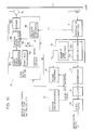
- Fig. 1 is a circuit block diagram of a recording system of a digital VTR showing the first embodiment of the present invention.
- the recording system circuit includes an A/D converter 11 for converting an analog television signal to a digital signal, a compression encoder 12 for compressing data, an ECC encoder 13 for checking and correcting an error (hereinafter referred to as "ECC"), a modulation processing circuit 14 for recording data, a recording amplifier 15 for amplifying a recording signal, a pilot signal generating circuit 16 for generating a pilot signal forATF, and a system synchronizing circuit 17 for generating a frame synchronizing signal FP in response to a television signal.
- the frame synchronizing signal FP is applied to compression encoder 12, ECC encoder 13, modulation processing circuit 14, and pilot signal generating circuit 16.
- Modulation processing circuit 14 includes a segment code generating circuit 14b for generating a segment code, and a modulating circuit 14a for modulating video data and the segment code for recording.
- Magnetic head 2 is driven by a recording signal amplified by recording amplifier 15 to record the recording signal on a track on magnetic tape 1.
- Fig. 2 is a circuit block diagram of a reproducing system in the embodiment shown in Fig. 1.
- the reproducing system circuit includes a reproducing amplifier 21 for amplifying a signal reproduced from magnetic tape 1 through magnetic head 2, a demodulation processing circuit 22 for carrying out demodulation processing for the reproduced signal, an ECC decoder 23 for carrying out ECC processing for a demodulated signal, a compression decoder 24 for decompressing data, a D/A converter 25 for converting a digital signal to an analog signal, a phase comparing circuit 26 for the frame synchronizing signal FP and a segment code signal SC, a system synchronizing circuit 27 for generating the frame synchronizing signal FP, and a servo system control circuit 28 for controlling the servo system including a capstan motor 29.
- Servo system control circuit 28 includes a capstan servo system circuit and a drum servo system circuit.
- the capstan servo system circuit includes a tracking error generating circuit 281 for providing a tracking error signal TE in response to a detected pilot signal PL, a fixed bias circuit 283 for generating a fixed bias voltage for adjusting a segment phase, and a switching circuit 282 controlled in response to the segment error signal SE.
- a feedback loop constituting the capstan servo system is made up of a speed error generating circuit 284, a capstan error generating circuit 285, and a motor driving circuit 286.
- Segment code generating circuit 14b shown in Fig. 1 generates the segment code signal SC in the manner shown in Fig. 3 in response to the frame synchronizing signal FP. More specifically, in the example shown in Fig. 3, in the recording mode, the segment code signal SC (c1, c2, ...) started in response to fall of the frame synchronizing signal FP is generated from segment code generating circuit 14b.
- the segment code signal SC is modulated by modulating circuit 14a for recording with video data applied from ECC encoder 13, and the modulated signal is applied to recording amplifier 15.
- pilot signal generating circuit 16 also generates four pilot signals PL (f1, f2, f3, and f4) each having a different frequency in response to the frame synchronizing signal FP.
- the pilot signal PL is applied to recording amplifier 15.
- the pilot signal PL is superimposed on a video signal applied from modulation processing circuit 14.
- the superimposed signal is amplified, and the amplified signal is applied to magnetic head 2. Therefore, recording signals recorded on magnetic tape 1 are recorded on respective recording tracks on magnetic tape 1 in a signal phase manner shown in Fig. 3.
- a signal reproduced through magnetic head 2 shown in Fig. 2 is amplified by reproducing amplifier 21.
- the reproduction pilot signal PL included in the amplified signal is applied to servo system control circuit 28.
- the reproducing signal including the segment code signal is applied to demodulating circuit 22a to cause demodulation processing to be carried out.
- the segment code signal included in the reproducing signal is detected by a segment code detecting circuit 22b, and the detected segment code signal SC is applied to phase comparing circuit 26.
- Phase comparing circuit 26 compares a fall timing of the frame synchronizing signal FP applied from system synchronizing circuit 27 with a timing at which code c1 included in the segment code signal SC appears. When these two timings do not match with each other, that is, when a phase error is generated, a segment error signal SE for correcting the phase error is applied to servo system control circuit 28. Servo system control circuit 28 controls the rotation speed of capstan motor 29 so that the phase error should be corrected in response to the segment error signal SE.
- the segment error signal SE for correcting the state is applied to servo system control circuit 28.
- the rotation speed of capstan motor 29 is changed under the control of servo system control circuit 28.
- the rotation speed of capstan motor 29 is controlled so that the segment code signal SC is reproduced in the signal manner shown in Fig. 3 also in the reproduction mode.
- step 51 an operation in the VTR of the servo system in the reproduction mode (PB mode) is detected.
- the process goes to step 52.
- step 52 the servo lock state of the capstan servo system is detected. Detection of the servo lock state is recognized by detecting output of the tracking error signal TE indicating "zero error" from tacking error generating circuit 281 show in Fig. 2.
- the capstan servo system in the servo lock state means that the segment code in the reproduced signal can be detected in segment code detecting circuit 226 shown in Fig. 2.
- the process goes to step 53.
- step 52 if the capstan servo system is not in the servo lock state, phase comparing circuit 26 provides the segment error signal SE of a high level. Therefore, also in this case, switching circuit 282 is connected to the side of tracking error generating circuit 281, and a normal tracking error correcting operation is carried out.
- phase comparing circuit 26 determines whether or not the segment phase is synchronized with the frame synchronizing signal FP. More specifically, when the frame synchronizing signal FP falls, the code "c1" of the segment code signal SC, that is, reproduction of the start flag signal, is detected. In other words, in the phase relation shown in Fig. 3, it is determined whether or not the segment code signal SC is reproduced. When the phase relation shown in Fig. 3 is satisfied, that is, when the segment phases are matched, the process goes to step 54.
- step 54 the segment error signal SE of a high level is provided from phase comparing circuit 26 shown in Fig. 2.
- Switching circuit 282 shown in Fig. 2 is connected to the side of tracking error generating circuit 281 in response to the signal SE of a high level. Therefore, the output signal TE from tracking error generating circuit 281 is applied to capstan error generating circuit 285. In other words, since the segment phases are matched in this state, the rotation speed of capstan motor 29 is not changed for adjustment of the segment phases.
- step 56 the segment error signal SE of a low level is provided from phase comparing circuit 26 shown in Fig. 2.
- Switching circuit 282 is connected to the side of fixed bias circuit 283 in response to the signal SE of a low level.
- a predetermined fixed bias voltage is applied to capstan error generating circuit 285 from fixed voltage circuit 283 through switching circuit 282 (step 57).
- the rotation speed of capstan motor 29 is changed, and the phase difference between the frame synchronizing signal FP and the segment code signal SC is changed.
- step 57 the process returns to step 52, and the process from steps 52 to 57 is repeated. Therefore, even if the segment phases are not matched as shown, for example, in Fig. 4, by repetition of the process of steps 52 to 57, the normal phase relation shown in Fig. 3 can be obtained.
- Fig. 6 shows a track formed on the magnetic tape.
- a television signal of one field is divided into six segments s1 to s6, and the six segments s1 to s6 are recorded on six tracks T1 to T6 shown in Fig. 6, respectively.
- one recording track has a recording format shown in Fig. 7.
- one recording track includes preamble regions 31, 35 and 39, a video signal recording region 32, postamble regions 33, 37 and 41, guard regions 34 and 38, a sound signal recording region 36, and an additional information recording region 40.
- Video signal recording region 32 is constituted of a number of blocks.
- One block in video signal recording region 32 includes a synchronizing signal recording region 321, an ID information recording region 322, a video data recording region 323, and an error correction parity recording region 324.
- the segment code signal SC generated from the segment code generating circuit shown in Fig. 1 is recorded in ID information recording region 322 shown in Fig. 7.
- Fig. 7 shows region 322 where the segment code signal SC is recorded in the digital VTR
- segment code signal SC is recorded in segment synchronizing signal recording region 45 shown in Fig. 8, when the present invention is applied to an analog VTR.
- Fig. 8 shows a recording format of one track on a magnetic tape recorded by an analog VTR. Referring to Fig. 8, one recording track includes a segment synchronizing signal recording region 45, and a video signal recording region 46.
- Fig. 9 is a circuit block diagram of a recording system of an analog VTR showing the second embodiment of the present invention.
- the recording system circuit includes an auto gain control (AGC) circuit 61 for receiving a television signal, a preemphasis circuit 62, a clamp circuit 63, a white clip circuit 64, a modulation processing circuit 65 including a modulating circuit 65a and a segment code generating circuit65b, a recording amplifier66, a pilotsig- nal generating circuit 67, and a system synchronizing circuit 68 for generating a frame synchronizing signal FP.
- AGC auto gain control
- Fig. 10 is a circuit block diagram of reproducing system in the second embodiment.
- the reproducing system circuit includes a reproducing amplifier 71, a demodulation processing circuit 72 including a demodulating circuit 72 and a segment code detecting circuit 72b, a deemphasis circuit 73, a clamp circuit 74, a video signal output circuit 75, a phase comparing circuit 76, and a servo system control circuit 78.
- Servo system control circuit 78 includes a drum servo system circuit and a capstan servo system circuit.
- the capstan servo system circuit includes a tracking error signal generating circuit 781, a switching circuit 782, a fixed bias circuit 783, a speed error signal generating circuit 784, a capstan error signal generating circuit 785, and a motor driving circuit 786 for driving a capstan motor 79.
- segment codes c1, c2, ... generated in the recording mode, are recorded with divided segments s1, s2, ... of a television signal, respectively.
- the recording location of the segment code signal SC is segment synchronizing signal recording region 45 shown in Fig. 8.
- segment codes c1, c2, ... recorded on each recording track on the magnetic tape are read out by segment code detecting circuit 72b shown in Fig. 10, and the rotation speed of capstan motor 79 is controlled so that a reproducing signal can be obtained in the phase relation in the recording mode, that is, in the manner shown in Fig. 3.
- the frame synchronizing signal FP is synchronized with the segment code signal SC in the reproduction mode with the same phase relation as in the recording mode by applying the present invention to a digital VTR and an analog VTR, a normal or stable video can be reproduced in the digital VTR or the analog VTR.
- the segment recording system is needed in order to implement high density recording and/orwide band recording, as described above, by applying the present invention to the digital VTR or the analog VTR, a desired video can be reproduced under requirements of high density recording and wide band recording.
- the ATF system using four pilot signals PL (f1 to f4) each having a different frequency are used in the above-described first and second embodiments.
- the present invention can be applied to a VTR of the ATF system using two pilot signals PL' (f1' and f2') each having a different frequency.
- a segment code signal SC' and the pilot signal PL' are recorded on a magnetic tape with the phase relation shown in Fig. 11. Even if the phase relation as shown in Fig. 12 is obtained in the reproduction mode, it is possible to obtain a reproduction signal in a desired phase relation in the reproduction mode, that is, in the phase relation shown in Fig. 11, by controlling the rotation speed of the capstan motor.
- the present invention can be applied to a VTR of the ATF system using an envelope detector.
- tracking control is carried out so that the envelope of a reproduction signal is maximized, recording and reproduction of a segment code signal and adjustment of the segment phase are carried out in the same manner as those in the above-described embodiments.
Landscapes
- Engineering & Computer Science (AREA)
- Multimedia (AREA)
- Signal Processing (AREA)
- Television Signal Processing For Recording (AREA)
- Adjustment Of The Magnetic Head Position Track Following On Tapes (AREA)
- Signal Processing For Digital Recording And Reproducing (AREA)
Abstract
Description
- The present invention relates generally to magnetic recording/reproducing apparatuses, and more particularly, to a magnetic recording/reproducing apparatus using a segment recording system. The present invention has particular applicability to digital and analog video tape recorders (VTRs).
- A conventional magnetic recording/reproducing apparatus using a magnetic tape such as a video tape recorder (hereinafter referred to as "VTR") as a recording medium records recording signals using a magnetic head on a number of video tracks formed obliquely on the magnetic tape. In reproduction, a magnetic head traces precisely on the recorded video tracks to reproduce the recorded signals. In order to make the video tracks to be traced precisely, as a conventional tracking system known is Automatic Track Finding (hereinafter referred to as "ATF") of a fourfrequency pilot signal system.
- The four frequency pilot signal system ATF is used in, for example, a stationary VTR or an 8mm VTR including a camera, or a camcorder. In the four frequency pilot signal system ATF, four pilot signals f1 to f4 each having a different frequency are superimposed on a video signal, and the superimposed signal is recorded on the magnetic tape. More specifically, since pilot signals each having a different frequency are recorded between adjoining two video tracks, crosstalk of pilot signals reproduced from two adjoining tracks in the reproduction operation is detected, and tracking control for tracing the magnetic head precisely is carried out in response to the level of two reproduced pilot signals.
- Fig. 13 is a schematic diagram showing arrangement of four magnetic heads on a drum in a mechanism used in a conventional 8mm camcorder or a VHS camcorder. Referring to Fig. 13, four
magnetic heads drum 83 for recording and reproducing. - Fig. 14 is a signal recording chart for explaining a recording operation in the ATF system using a four frequency pilot signal. Referring to Fig. 14, the abscissa shows a rotation angle (radian) of
drum 83 shown in Fig. 13. Signal recording withmagnetic head 81a is carried out at a rotation angle in the range of 0 to 3/2π. Signal recording withmagnetic head 80b is carried out at a rotation angle in the range of 3/2π to 37t. Signal recording withmagnetic head 81 b is carried out at a rotation angle in the range of 37c to 9/2π. Signal recording withmagnetic head 80a is carried out at a rotation angle in the range of 9/2π to 6π. - As is seen from Fig. 14, when
drum 83 rotates by 3/2π radian, a television signal of one field is recorded on one track on the magnetic tape by each magnetic head. More specifically, respective segment signals s1 and s2 shown in Fig. 14 are recorded on four tracks on the magnetic tape. Two fields are constituted of two segment signals s1 and s2, thereby constituting a television signal of one frame.Drum 83 shown in Fig. 13 rotates at, for example, 2700rpm, and the magnetic heads are switched for every 3/2×. - Fig. 15 is a timing chart for explaining a recording operation of an ATF system VTR using the four frequency pilot signal. Referring to Fig. 15, during a half period of a frame synchronizing signal FP, that is, one field period, one segment of the television signal is recorded. More specifically, each of segment signals s1 and s2 shown in Fig. 14 is recorded on corresponding one track in the corresponding half period of the frame synchronizing signal FP.
- In the ATF system using the four frequency pilot signal, pilot signals having different frequencies are recorded on respective tracks as described above. Therefore, in the example shown in Fig. 15, respective ones of the pilotsignals f1 to f4 are recorded sequentially on respective segments. As is seen from Fig 15, fourfrequency pilot signals f1 to f4 rotate in the order of f1 to f4, and are recorded sequentially in respective segments.
- In the signal recording shown in Fig. 14, since a television signal of one field is recorded on one track, the signal recording system is referred to as "non-segment recording system." Conversely, "segment recording system" is known as a signal recording system in which a television signal of one field is divided into a plurality of segments, and the plurality of the segment signals are recorded on a plurality of tracks.
- In order to improve video picture quality, high density recording and wide band recording of television signals have recently been developed. In order to implement high density recording and wide band recording, it is necessary to further increase a relative speed between a magnetic tape and a magnetic head. Therefore, the revolution per minutes rotation of a drum having a magnetic head is increased, and the aforementioned segment recording system is required.
- The above-described ATF system using the four frequency pilot signal is used in the non-segment recording system, while Control Track (hereinafter referred to as "CTL") system used in UNIHI-VTR and the like is heretofore known as a tracking control system in the segment recording system. In the UNIHI-VTR, the television signal constituting one frame is divided into six segments, and the six segment signals are recorded on six tracks. Since a control signal (CTL signal) generated for every one frame period is recorded on a control track on the magnetic tape in the CTL system, it is possible to easily match the phase of the six segment signals with the phase of the frame synchronizing signal in reproduction.
- Since the CTL system needs a region dedicated to recording of a control signal, that is, a control track, in the magnetic tape, the ATF system requiring no dedicated region is preferable for high density recording In other words, in order to implement high density recording and wide band recording, the ATF system is more suitable in which a video signal having a pilot signal superimposed thereon is recorded. However, segment recording in a VTR employing the ATF system causes the following problem.
- Fig. 16 is a schematic diagram showing arrangement of two magnetic heads on a drum in a VTR showing the background of the present invention. Referring to Fig. 16, two
magnetic heads drum 84. For the purpose of high density recording and wide band recording,drum 84 rotates at a speed of 5400rpm. Therefore, a television signal of one field is divided into three segments, resulting in division of the television signal of one frame into six segments. In other words, the television signal constituting one frame is recorded on six tracks on the magnetic tape. - Fig. 17 is a signal recording chart for explaining a recording operation in a VTR using
magnetic heads drum 84.
Signal recording usingmagnetic head 82a is carried out at a rotation angle in the range of 0 to (segment s1): -
magnetic head 82b, in the range of to 2n (segment s2): -
magnetic head 82a, in the range of 2n to 3n (segment s3): -
magnetic head 82b, in the range of 3n to 4n (segment s4): -
magnetic head 82a, in the range of 4n to 5n (segment s5): -
magnetic head 82b, in the range of 5n to 6n (segment s6). These segments s1 to s6 of the television signal are recorded on the six tracks on the magnetic tape, respectively. - Figs. 18A to 18C are timing charts for explaining recording and reproducing operations in a VTR using
magnetic heads - When the signal recording is carried out in the manner shown in Fig. 18A, the reproducing operation must be carried out in the same manner. More specifically, in the example shown in Fig. 18A, when the frame synchronizing signal FP falls, the segment s1 of the recorded television signal needs to be reproduced. In otherwords, the frame synchronizing signal FP must be in synchronization with the segment s1 of the reproduced television signal. If the first segment s1 of the reproduced television signal is notsynchron- ized with the fall of the frame synchronizing signal FP, a desired video cannot be reproduced. Therefore, the reproducing operation needs to be controlled in the manner shown in Fig. 18A, that is, the manner in which the segment s1 of the reproduced television signal and the fall of the frame synchronizing signal FP are matched.
- As shown in Figs. 18B and 18C, however, when the frame synchronizing signal FP falls, it may happen that the segment s1 of the reproduced television signal cannot be obtained. In such a case, a desired video cannot be reproduced, and a measure is required.
- A simple measure in such a case is to determine a segment number from the reproduced pilot signal frequency to synchronize the segment s1 with the frame synchronizing signal by using a pilot signal having six frequencies corresponding to six segments. However, in order to generate and determine a pilot signal having six frequencies, the circuit configuration becomes much more complicated compared to the four frequency pilot signal system. Furthermore, increase in the number of segments means the further complicated circuit configuration.
- One object of the present invention is to reproduce a desired video in a magnetic recording/reproducing apparatus using a segment recording system, under a high density recording requirement.
- Another object of the present invention is to reproduce a desired video in a magnetic recording/reproducing apparatus using a segment recording system under a wide band recording requirement.
- The magnetic recording/reproducing apparatus according to the present invention divides a television signal of one field into a plurality of segments to record the same on a plurality of tracks on a magnetic tape. In one aspect, the magnetic recording/reproducing apparatus includes a magnetic head, a tape driving circuit for driving the magnetic tape, a synchronizing signal generating circuit for generating a predetermined synchronizing signal, a segment code generating circuit for generating a plurality of segment code signals indicating the plurality of segments in response to the synchronizing signal, a recording circuit for recording the plurality of segment code signals on the plurality of tracks on the magnetic tape through the magnetic head in synchronism with the synchronizing signal, a reproducing circuit for reproducing the plurality of segment code signals from the plurality of tracks on the magnetic tape through the magnetic head, and a control circuit for controlling the tape driving circuit so that the plurality of segment code signals reproduced by the reproducing circuit are synchronized with the predetermined synchronizing signal.
- In operation, the recording circuit records the plurality of segment code signals on the plurality of tracks on the magnetic tape through the magnetic head in response to the synchronizing signal. In the reproduction mode, the reproducing circuit reproduces the plurality of segment code signals from the plurality of tracks on the magnetic tape through the magnetic head. Since the control circuit controls the tape driving circuit so that the reproduced plurality of segment code signals are synchronized with the predetermined synchronizing signal, it is possible to reproduce a segment of a recorded television signal in the synchronous manner in the recording mode. As a result, a desired video can be reproduced under requirements of high density recording and wide band recording.
- According to another aspect of the present invention, the magnetic recording/reproducing apparatus includes a magnetic head, a tape driving circuit for driving a magnetic tape, a synchronizing signal generating circuit for generating a predetermined synchronizing signal, a start flag generating circuit for generating a start flag signal indicating start of a plurality of segments in response to the synchronizing signal, a recording circuit for recording the start flag signal on the first one of a predetermined number of tracks on the magnetic tape in synchronism with a predetermined edge of the synchronizing signal, a reproducing circuit for reproducing the recorded start flag signal from the track on the magnetic tape, and a control circuit for controlling the tape driving circuit so that the reproduced start flag signal is synchronized with predetermined edge of the predetermined synchronizing signal.
- The foregoing and other objects, features, aspects and advantages of the present invention will become more apparent from the following detailed description of the present invention when taken in conjunction with the accompanying drawings.
-
- Fig. 1 is a circuit block diagram of a recording system of a digital VTRshowing a first embodiment of the present invention.
- Fig. 2 is a circuit block diagram of a reproducing system in the first embodiment.
- Fig. 3 is a timing chart for explaining the phase relation in a recording operation and a normal reproducing operation of the first embodiment.
- Fig. 4 is a timing chart for explaining an abnormal phase relation in the reproducing operation of the first embodiment.
- Fig. 5 is a flow chart for explaining operations of the reproducing system circuit shown in Fig. 2.
- Fig. 6 is a concept diagram of a recording track formed on a magnetic tape.
- Fig. 7 is a recording format of the recording track of the first embodiment.
- Fig. 8 is a recording format of a recording track of a second embodiment.
- Fig. 9 is a circuit block diagram of a recording system of an analog VTR showing the second embodiment of the present invention.
- Fig. 10 is a circuit block diagram of a reproducing system in the second embodiment.
- Fig. 11 is a timing chart for explaining the phase relation of a recording operation and a normal reproducing operation of a third embodiment of the present invention.
- Fig. 12 is a timing chart for explaining an abnormal phase relation in the reproducing operation of the third embodiment.
- Fig. 13 is a schematic diagram showing arrangement of four magnetic heads on a drum in a conventional camcorder or a movie.
- Fig. 14 is a signal recording chart for explaining a recording operation in a VTR of a four frequency pilot signal ATF system.
- Fig. 15 is a timing chart for explaining the phase relation of the VTR of the four frequency pilot signal ATF system.
- Fig. 16 is a schematic diagram showing arrangement of two magnetic heads on a drum in a VTR showing the background of the present invention.
- Fig. 17 is a signal recording chart for explaining the recording operation in the VTR using the magnetic heads shown in Fig. 16.
- Fig. 18A is a timing chart showing a normal phase relation in the VTR using the magnetic heads shown in Fig. 16.
- Figs. 18B and 18C are timing charts for explaining an abnormal phase relation in the VTR using the magnetic heads shown in Fig. 16.
- Fig. 1 is a circuit block diagram of a recording system of a digital VTR showing the first embodiment of the present invention. Referring to Fig. 1, the recording system circuit includes an A/
D converter 11 for converting an analog television signal to a digital signal, acompression encoder 12 for compressing data, anECC encoder 13 for checking and correcting an error (hereinafter referred to as "ECC"), amodulation processing circuit 14 for recording data, arecording amplifier 15 for amplifying a recording signal, a pilotsignal generating circuit 16 for generating a pilot signal forATF, and asystem synchronizing circuit 17 for generating a frame synchronizing signal FP in response to a television signal. - The frame synchronizing signal FP is applied to
compression encoder 12,ECC encoder 13,modulation processing circuit 14, and pilotsignal generating circuit 16.Modulation processing circuit 14 includes a segmentcode generating circuit 14b for generating a segment code, and amodulating circuit 14a for modulating video data and the segment code for recording.Magnetic head 2 is driven by a recording signal amplified by recordingamplifier 15 to record the recording signal on a track onmagnetic tape 1. - Fig. 2 is a circuit block diagram of a reproducing system in the embodiment shown in Fig. 1. Referring to Fig. 2, the reproducing system circuit includes a reproducing
amplifier 21 for amplifying a signal reproduced frommagnetic tape 1 throughmagnetic head 2, ademodulation processing circuit 22 for carrying out demodulation processing for the reproduced signal, anECC decoder 23 for carrying out ECC processing for a demodulated signal, acompression decoder 24 for decompressing data, a D/A converter 25 for converting a digital signal to an analog signal, aphase comparing circuit 26 for the frame synchronizing signal FP and a segment code signal SC, asystem synchronizing circuit 27 for generating the frame synchronizing signal FP, and a servosystem control circuit 28 for controlling the servo system including acapstan motor 29. - Servo
system control circuit 28 includes a capstan servo system circuit and a drum servo system circuit. The capstan servo system circuit includes a trackingerror generating circuit 281 for providing a tracking error signal TE in response to a detected pilot signal PL, a fixedbias circuit 283 for generating a fixed bias voltage for adjusting a segment phase, and aswitching circuit 282 controlled in response to the segment error signal SE. A feedback loop constituting the capstan servo system is made up of a speed error generating circuit 284, a capstanerror generating circuit 285, and amotor driving circuit 286. - Description will be first given to a schematic synchronizing operation between a segment of a reproduced television signal and the frame synchronizing signal FP in the digital VTR shown in Figs. 1 and 2, with reference to Figs. 3 and 4. Segment
code generating circuit 14b shown in Fig. 1 generates the segment code signal SC in the manner shown in Fig. 3 in response to the frame synchronizing signal FP. More specifically, in the example shown in Fig. 3, in the recording mode, the segment code signal SC (c1, c2, ...) started in response to fall of the frame synchronizing signal FP is generated from segmentcode generating circuit 14b. The segment code signal SC is modulated by modulatingcircuit 14a for recording with video data applied fromECC encoder 13, and the modulated signal is applied torecording amplifier 15. - On the other hand, pilot
signal generating circuit 16 also generates four pilot signals PL (f1, f2, f3, and f4) each having a different frequency in response to the frame synchronizing signal FP. The pilot signal PL is applied torecording amplifier 15. - In
recording amplifier 15, the pilot signal PL is superimposed on a video signal applied frommodulation processing circuit 14. The superimposed signal is amplified, and the amplified signal is applied tomagnetic head 2. Therefore, recording signals recorded onmagnetic tape 1 are recorded on respective recording tracks onmagnetic tape 1 in a signal phase manner shown in Fig. 3. - In the reproduction mode, a signal reproduced through
magnetic head 2 shown in Fig. 2 is amplified by reproducingamplifier 21. The reproduction pilot signal PL included in the amplified signal is applied to servosystem control circuit 28. The reproducing signal including the segment code signal is applied to demodulatingcircuit 22a to cause demodulation processing to be carried out. The segment code signal included in the reproducing signal is detected by a segmentcode detecting circuit 22b, and the detected segment code signal SC is applied to phase comparingcircuit 26. -
Phase comparing circuit 26 compares a fall timing of the frame synchronizing signal FP applied fromsystem synchronizing circuit 27 with a timing at which code c1 included in the segment code signal SC appears. When these two timings do not match with each other, that is, when a phase error is generated, a segment error signal SE for correcting the phase error is applied to servosystem control circuit 28. Servosystem control circuit 28 controls the rotation speed ofcapstan motor 29 so that the phase error should be corrected in response to the segment error signal SE. - For example, when the frame synchronizing signal FP is not synchron ized wit h t he segment code signal SC as shown in Fig. 4, the segment error signal SE for correcting the state is applied to servo
system control circuit 28. The rotation speed ofcapstan motor 29 is changed under the control of servosystem control circuit 28. Finally, the rotation speed ofcapstan motor 29 is controlled so that the segment code signal SC is reproduced in the signal manner shown in Fig. 3 also in the reproduction mode. These operations are shown more specifically in a flow chart shown in Fig. 5. - Referring to Fig. 5, in
step 51, an operation in the VTR of the servo system in the reproduction mode (PB mode) is detected. When the operation of the servo system in the reproduction mode is detected, the process goes to step 52. - In
step 52, the servo lock state of the capstan servo system is detected. Detection of the servo lock state is recognized by detecting output of the tracking error signal TE indicating "zero error" from tackingerror generating circuit 281 show in Fig. 2. The capstan servo system in the servo lock state means that the segment code in the reproduced signal can be detected in segment code detecting circuit 226 shown in Fig. 2. When the segment code can be detected, the process goes to step 53. - In
step 52, if the capstan servo system is not in the servo lock state,phase comparing circuit 26 provides the segment error signal SE of a high level. Therefore, also in this case, switchingcircuit 282 is connected to the side of trackingerror generating circuit 281, and a normal tracking error correcting operation is carried out. - In
step 53,phase comparing circuit 26 determines whether or not the segment phase is synchronized with the frame synchronizing signal FP. More specifically, when the frame synchronizing signal FP falls, the code "c1" of the segment code signal SC, that is, reproduction of the start flag signal, is detected. In other words, in the phase relation shown in Fig. 3, it is determined whether or not the segment code signal SC is reproduced. When the phase relation shown in Fig. 3 is satisfied, that is, when the segment phases are matched, the process goes to step 54. - In
step 54, the segment error signal SE of a high level is provided fromphase comparing circuit 26 shown in Fig. 2.Switching circuit 282 shown in Fig. 2 is connected to the side of trackingerror generating circuit 281 in response to the signal SE of a high level. Therefore, the output signal TE from trackingerror generating circuit 281 is applied to capstanerror generating circuit 285. In other words, since the segment phases are matched in this state, the rotation speed ofcapstan motor 29 is not changed for adjustment of the segment phases. - When the segment phases are not matched, the process goes to step 56. In
step 56, the segment error signal SE of a low level is provided fromphase comparing circuit 26 shown in Fig. 2.Switching circuit 282 is connected to the side of fixedbias circuit 283 in response to the signal SE of a low level. As a result, a predetermined fixed bias voltage is applied to capstanerror generating circuit 285 from fixedvoltage circuit 283 through switching circuit 282 (step 57). As a result, the rotation speed ofcapstan motor 29 is changed, and the phase difference between the frame synchronizing signal FP and the segment code signal SC is changed. Afterstep 57, the process returns to step 52, and the process fromsteps 52 to 57 is repeated. Therefore, even if the segment phases are not matched as shown, for example, in Fig. 4, by repetition of the process ofsteps 52 to 57, the normal phase relation shown in Fig. 3 can be obtained. - The following description will be given to the recording location on the magnetic tape of the segment code signal SC used in the above-described embodiment. Fig. 6 shows a track formed on the magnetic tape. In the above-described embodiment, a television signal of one field is divided into six segments s1 to s6, and the six segments s1 to s6 are recorded on six tracks T1 to T6 shown in Fig. 6, respectively. In the embodiment shown in Fig. 1, that is, in a digital VTR, one recording track has a recording format shown in Fig. 7.
- Referring to Fig. 7, one recording track includes
preamble regions signal recording region 32,postamble regions guard regions signal recording region 36, and an additionalinformation recording region 40. Videosignal recording region 32 is constituted of a number of blocks. One block in videosignal recording region 32 includes a synchronizingsignal recording region 321, an IDinformation recording region 322, a videodata recording region 323, and an error correctionparity recording region 324. The segment code signal SC generated from the segment code generating circuit shown in Fig. 1 is recorded in IDinformation recording region 322 shown in Fig. 7. - Although the recording format shown in Fig. 7 shows
region 322 where the segment code signal SC is recorded in the digital VTR, segment code signal SC is recorded in segment synchronizingsignal recording region 45 shown in Fig. 8, when the present invention is applied to an analog VTR. Fig. 8 shows a recording format of one track on a magnetic tape recorded by an analog VTR. Referring to Fig. 8, one recording track includes a segment synchronizingsignal recording region 45, and a videosignal recording region 46. - Fig. 9 is a circuit block diagram of a recording system of an analog VTR showing the second embodiment of the present invention. Referring to Fig. 9, the recording system circuit includes an auto gain control (AGC)
circuit 61 for receiving a television signal, apreemphasis circuit 62, aclamp circuit 63, awhite clip circuit 64, amodulation processing circuit 65 including a modulating circuit 65a and a segment code generating circuit65b, a recording amplifier66, a pilotsig-nal generating circuit 67, and asystem synchronizing circuit 68 for generating a frame synchronizing signal FP. - Fig. 10 is a circuit block diagram of reproducing system in the second embodiment. Referring to Fig. 10, the reproducing system circuit includes a reproducing
amplifier 71, ademodulation processing circuit 72 including ademodulating circuit 72 and a segmentcode detecting circuit 72b, adeemphasis circuit 73, aclamp circuit 74, a videosignal output circuit 75, aphase comparing circuit 76, and a servosystem control circuit 78. Servosystem control circuit 78 includes a drum servo system circuit and a capstan servo system circuit. - The capstan servo system circuit includes a tracking error
signal generating circuit 781, aswitching circuit 782, a fixedbias circuit 783, a speed errorsignal generating circuit 784, a capstan errorsignal generating circuit 785, and amotor driving circuit 786 for driving acapstan motor 79. - In the second embodiment shown in Figs. 9 and 10, operations basically the same as those of the first embodiment shown in Figs. 1 and 2 are carried out. More specifically, segment codes c1, c2, ... , generated in the recording mode, are recorded with divided segments s1, s2, ... of a television signal, respectively. The recording location of the segment code signal SC is segment synchronizing
signal recording region 45 shown in Fig. 8. In the reproduction mode, segment codes c1, c2, ... recorded on each recording track on the magnetic tape are read out by segmentcode detecting circuit 72b shown in Fig. 10, and the rotation speed ofcapstan motor 79 is controlled so that a reproducing signal can be obtained in the phase relation in the recording mode, that is, in the manner shown in Fig. 3. - As described above, since the frame synchronizing signal FP is synchronized with the segment code signal SC in the reproduction mode with the same phase relation as in the recording mode by applying the present invention to a digital VTR and an analog VTR, a normal or stable video can be reproduced in the digital VTR or the analog VTR. Although the segment recording system is needed in order to implement high density recording and/orwide band recording, as described above, by applying the present invention to the digital VTR or the analog VTR, a desired video can be reproduced under requirements of high density recording and wide band recording.
- It should be noted that the ATF system using four pilot signals PL (f1 to f4) each having a different frequency are used in the above-described first and second embodiments. However, the present invention can be applied to a VTR of the ATF system using two pilot signals PL' (f1' and f2') each having a different frequency. More specifically, in the other embodiments, a segment code signal SC' and the pilot signal PL' are recorded on a magnetic tape with the phase relation shown in Fig. 11. Even if the phase relation as shown in Fig. 12 is obtained in the reproduction mode, it is possible to obtain a reproduction signal in a desired phase relation in the reproduction mode, that is, in the phase relation shown in Fig. 11, by controlling the rotation speed of the capstan motor.
- Although the tracking error is detected by using the pilot signal in the above-described embodiment, the present invention can be applied to a VTR of the ATF system using an envelope detector. In that case, although tracking control is carried out so that the envelope of a reproduction signal is maximized, recording and reproduction of a segment code signal and adjustment of the segment phase are carried out in the same manner as those in the above-described embodiments.
- Although the present invention has been described and illustrated in detail, it is clearly understood that the same is by way of illustration and example only and is not to be taken by way of limitation, the spirit and scope of the present invention being limited only by the terms of the appended claims.
Claims (13)
Applications Claiming Priority (2)
| Application Number | Priority Date | Filing Date | Title |
|---|---|---|---|
| JP4051006A JP2753173B2 (en) | 1992-03-10 | 1992-03-10 | Tracking control device in multi-segment recording |
| JP51006/92 | 1992-03-10 |
Publications (3)
| Publication Number | Publication Date |
|---|---|
| EP0560596A2 true EP0560596A2 (en) | 1993-09-15 |
| EP0560596A3 EP0560596A3 (en) | 1994-03-23 |
| EP0560596B1 EP0560596B1 (en) | 2007-07-18 |
Family
ID=12874691
Family Applications (1)
| Application Number | Title | Priority Date | Filing Date |
|---|---|---|---|
| EP93301831A Expired - Lifetime EP0560596B1 (en) | 1992-03-10 | 1993-03-10 | Improved magnetic recording/reproducing apparatus using segment recording system |
Country Status (8)
| Country | Link |
|---|---|
| US (1) | US5396373A (en) |
| EP (1) | EP0560596B1 (en) |
| JP (1) | JP2753173B2 (en) |
| KR (1) | KR960005942B1 (en) |
| CN (1) | CN1048610C (en) |
| DE (1) | DE69334154T2 (en) |
| ES (1) | ES2288297T3 (en) |
| MY (1) | MY109162A (en) |
Cited By (7)
| Publication number | Priority date | Publication date | Assignee | Title |
|---|---|---|---|---|
| EP0655735A1 (en) * | 1993-11-16 | 1995-05-31 | Canon Kabushiki Kaisha | Signal reproducing apparatus |
| EP0708440A1 (en) * | 1994-10-21 | 1996-04-24 | Sony Corporation | Variable-speed playback apparatus for digital video signals |
| EP0644531A3 (en) * | 1993-09-17 | 1997-09-24 | Matsushita Electric Industrial Co Ltd | Information playback device. |
| EP0564234B1 (en) * | 1992-04-03 | 1999-01-20 | Matsushita Electric Industrial Co., Ltd. | Reproducing apparatus |
| EP0798721A3 (en) * | 1996-03-27 | 2000-07-26 | Sony Corporation | Digital video recording apparatus and method |
| KR100265009B1 (en) * | 1996-02-06 | 2000-10-02 | 구자홍 | Recording and reproducing apparatus and method for digital vcr |
| KR100265007B1 (en) * | 1996-02-05 | 2000-10-02 | 구자홍 | Digital VR Video Recorder |
Families Citing this family (4)
| Publication number | Priority date | Publication date | Assignee | Title |
|---|---|---|---|---|
| JPH01254157A (en) * | 1988-03-31 | 1989-10-11 | Nippon Zeon Co Ltd | Infection preventing tool |
| KR100584532B1 (en) * | 1999-02-09 | 2006-05-30 | 삼성전자주식회사 | Servo control device and method of digital video camcorder |
| AU2002309987A1 (en) | 2001-05-25 | 2002-12-09 | Hill-Rom Services, Inc. | Modular patient room |
| JP2006094411A (en) * | 2004-09-27 | 2006-04-06 | Toshiba Corp | Information processing apparatus and external device control method thereof |
Family Cites Families (10)
| Publication number | Priority date | Publication date | Assignee | Title |
|---|---|---|---|---|
| JPS62234478A (en) * | 1986-04-04 | 1987-10-14 | Matsushita Electric Ind Co Ltd | Video signal recording and reproducing device |
| JP2513204B2 (en) * | 1987-01-28 | 1996-07-03 | ソニー株式会社 | Speed control circuit of PCM signal reproducing device |
| JPS6423453A (en) * | 1987-07-17 | 1989-01-26 | Yamaha Corp | Rotation controller for rotary head |
| NL8801363A (en) * | 1988-05-27 | 1989-12-18 | Philips Nv | DEVICE FOR RECORDING OR PLAYING AN ELECTRIC SIGNAL. |
| JP2568255B2 (en) * | 1988-09-14 | 1996-12-25 | キヤノン株式会社 | Rotating head type playback device |
| JP2584006B2 (en) * | 1988-10-17 | 1997-02-19 | 株式会社日立製作所 | Magnetic recording / reproducing device |
| US5088077A (en) * | 1988-11-10 | 1992-02-11 | Ampex Corporation | Synchronization of record media transports and tracking adjustment |
| JP2830394B2 (en) * | 1989-12-07 | 1998-12-02 | ソニー株式会社 | Magnetic tape recording and / or reproducing apparatus |
| DE4015391A1 (en) * | 1990-05-14 | 1991-11-21 | Nokia Unterhaltungselektronik | VIDEO RECORDER FOR HDTV SIGNALS |
| JPH04349252A (en) * | 1991-05-27 | 1992-12-03 | Matsushita Electric Ind Co Ltd | playback device |
-
1992
- 1992-03-10 JP JP4051006A patent/JP2753173B2/en not_active Expired - Lifetime
-
1993
- 1993-02-26 MY MYPI93000357A patent/MY109162A/en unknown
- 1993-03-05 US US08/026,850 patent/US5396373A/en not_active Expired - Lifetime
- 1993-03-09 KR KR1019930003487A patent/KR960005942B1/en not_active Expired - Fee Related
- 1993-03-10 EP EP93301831A patent/EP0560596B1/en not_active Expired - Lifetime
- 1993-03-10 ES ES93301831T patent/ES2288297T3/en not_active Expired - Lifetime
- 1993-03-10 DE DE69334154T patent/DE69334154T2/en not_active Expired - Lifetime
- 1993-03-10 CN CN93103583A patent/CN1048610C/en not_active Expired - Fee Related
Cited By (10)
| Publication number | Priority date | Publication date | Assignee | Title |
|---|---|---|---|---|
| EP0564234B1 (en) * | 1992-04-03 | 1999-01-20 | Matsushita Electric Industrial Co., Ltd. | Reproducing apparatus |
| EP0644531A3 (en) * | 1993-09-17 | 1997-09-24 | Matsushita Electric Industrial Co Ltd | Information playback device. |
| EP0655735A1 (en) * | 1993-11-16 | 1995-05-31 | Canon Kabushiki Kaisha | Signal reproducing apparatus |
| US6134074A (en) * | 1993-11-16 | 2000-10-17 | Canon Kabushiki Kaisha | Reproducing apparatus having tracking control in accordance with track number information |
| EP0708440A1 (en) * | 1994-10-21 | 1996-04-24 | Sony Corporation | Variable-speed playback apparatus for digital video signals |
| US5930063A (en) * | 1994-10-21 | 1999-07-27 | Sony Corporation | Variable-speed playback apparatus for digital video signals |
| US6078456A (en) * | 1994-10-21 | 2000-06-20 | Sony Corporation | Variable-speed playback apparatus for digital video signals |
| KR100265007B1 (en) * | 1996-02-05 | 2000-10-02 | 구자홍 | Digital VR Video Recorder |
| KR100265009B1 (en) * | 1996-02-06 | 2000-10-02 | 구자홍 | Recording and reproducing apparatus and method for digital vcr |
| EP0798721A3 (en) * | 1996-03-27 | 2000-07-26 | Sony Corporation | Digital video recording apparatus and method |
Also Published As
| Publication number | Publication date |
|---|---|
| KR960005942B1 (en) | 1996-05-03 |
| DE69334154D1 (en) | 2007-08-30 |
| EP0560596B1 (en) | 2007-07-18 |
| ES2288297T3 (en) | 2008-01-01 |
| US5396373A (en) | 1995-03-07 |
| KR930020984A (en) | 1993-10-20 |
| CN1080103A (en) | 1993-12-29 |
| MY109162A (en) | 1996-12-31 |
| JP2753173B2 (en) | 1998-05-18 |
| DE69334154T2 (en) | 2008-03-13 |
| CN1048610C (en) | 2000-01-19 |
| EP0560596A3 (en) | 1994-03-23 |
| JPH05258403A (en) | 1993-10-08 |
Similar Documents
| Publication | Publication Date | Title |
|---|---|---|
| US4772960A (en) | Apparatus for recording and/or reproducing an information signal comprised of at least an audio signal and an index signal | |
| EP0560596B1 (en) | Improved magnetic recording/reproducing apparatus using segment recording system | |
| US5966496A (en) | Method of and apparatus for recording and reproducing digital information signal including sub-information | |
| US5781688A (en) | Method and apparatus for reproducing a compressed digital video signal at multiple speed | |
| US5182681A (en) | Rotating head magnetic recording and reproducing device having automatic tracking control function | |
| US4686584A (en) | Video signal reproduction apparatus and method having noise reduction for fast video reproduction | |
| US5438459A (en) | Method of processing and recording data while reproducing the same and apparatus for the method | |
| EP0172441B1 (en) | Tracking control system for a video tape recorder | |
| US4823206A (en) | Video signal recording and/or reproducing apparatus | |
| US5648879A (en) | Method of and apparatus for controlling the phase of a video signal | |
| KR100423177B1 (en) | Digital signal recording / reproducing apparatus and method | |
| US5937135A (en) | Tape-independent video signal recording and reproducing apparatus | |
| JPH1011844A (en) | Auto tracking device | |
| EP0357352B1 (en) | Video signal recording/reproducing apparatus | |
| JP2754731B2 (en) | Rotating head type playback device | |
| US6038095A (en) | Signal reproducing apparatus | |
| JPH05328274A (en) | Magnetic recording and reproducing device | |
| US6005741A (en) | Reproducing apparatus using pilot signal crosstalk for tracking control and using pilot signals to eliminate a back lock condition | |
| JPH0278050A (en) | auto tracking device | |
| JPH10188401A (en) | Magnetic recording / reproducing apparatus having head phase adjusting means | |
| JPS6213738B2 (en) | ||
| JPH02126786A (en) | Magnetic recording/reproducing device | |
| JPH0757392A (en) | Video signal recording and reproducing device | |
| JPS61104303A (en) | magnetic recording and reproducing device | |
| JPH02312048A (en) | Rotating head type reproducing device |
Legal Events
| Date | Code | Title | Description |
|---|---|---|---|
| PUAI | Public reference made under article 153(3) epc to a published international application that has entered the european phase |
Free format text: ORIGINAL CODE: 0009012 |
|
| AK | Designated contracting states |
Kind code of ref document: A2 Designated state(s): DE ES FR GB |
|
| PUAL | Search report despatched |
Free format text: ORIGINAL CODE: 0009013 |
|
| AK | Designated contracting states |
Kind code of ref document: A3 Designated state(s): DE ES FR GB |
|
| 17P | Request for examination filed |
Effective date: 19940922 |
|
| 17Q | First examination report despatched |
Effective date: 19980330 |
|
| GRAP | Despatch of communication of intention to grant a patent |
Free format text: ORIGINAL CODE: EPIDOSNIGR1 |
|
| GRAS | Grant fee paid |
Free format text: ORIGINAL CODE: EPIDOSNIGR3 |
|
| RAP1 | Party data changed (applicant data changed or rights of an application transferred) |
Owner name: SHARP KABUSHIKI KAISHA |
|
| GRAA | (expected) grant |
Free format text: ORIGINAL CODE: 0009210 |
|
| AK | Designated contracting states |
Kind code of ref document: B1 Designated state(s): DE ES FR GB |
|
| REG | Reference to a national code |
Ref country code: GB Ref legal event code: FG4D |
|
| REF | Corresponds to: |
Ref document number: 69334154 Country of ref document: DE Date of ref document: 20070830 Kind code of ref document: P |
|
| REG | Reference to a national code |
Ref country code: ES Ref legal event code: FG2A Ref document number: 2288297 Country of ref document: ES Kind code of ref document: T3 |
|
| ET | Fr: translation filed | ||
| PLBE | No opposition filed within time limit |
Free format text: ORIGINAL CODE: 0009261 |
|
| STAA | Information on the status of an ep patent application or granted ep patent |
Free format text: STATUS: NO OPPOSITION FILED WITHIN TIME LIMIT |
|
| 26N | No opposition filed |
Effective date: 20080421 |
|
| PGFP | Annual fee paid to national office [announced via postgrant information from national office to epo] |
Ref country code: FR Payment date: 20120319 Year of fee payment: 20 |
|
| PGFP | Annual fee paid to national office [announced via postgrant information from national office to epo] |
Ref country code: GB Payment date: 20120307 Year of fee payment: 20 |
|
| PGFP | Annual fee paid to national office [announced via postgrant information from national office to epo] |
Ref country code: DE Payment date: 20120411 Year of fee payment: 20 |
|
| REG | Reference to a national code |
Ref country code: DE Ref legal event code: R071 Ref document number: 69334154 Country of ref document: DE |
|
| REG | Reference to a national code |
Ref country code: GB Ref legal event code: PE20 Expiry date: 20130309 |
|
| PG25 | Lapsed in a contracting state [announced via postgrant information from national office to epo] |
Ref country code: GB Free format text: LAPSE BECAUSE OF EXPIRATION OF PROTECTION Effective date: 20130309 Ref country code: DE Free format text: LAPSE BECAUSE OF EXPIRATION OF PROTECTION Effective date: 20130312 |
|
| PGFP | Annual fee paid to national office [announced via postgrant information from national office to epo] |
Ref country code: ES Payment date: 20120327 Year of fee payment: 20 |
|
| REG | Reference to a national code |
Ref country code: ES Ref legal event code: FD2A Effective date: 20130726 |
|
| PG25 | Lapsed in a contracting state [announced via postgrant information from national office to epo] |
Ref country code: ES Free format text: LAPSE BECAUSE OF EXPIRATION OF PROTECTION Effective date: 20130311 |