EP0558284B1 - Method and apparatus for correcting printing distortions in an ink jet printer - Google Patents
Method and apparatus for correcting printing distortions in an ink jet printer Download PDFInfo
- Publication number
- EP0558284B1 EP0558284B1 EP93301348A EP93301348A EP0558284B1 EP 0558284 B1 EP0558284 B1 EP 0558284B1 EP 93301348 A EP93301348 A EP 93301348A EP 93301348 A EP93301348 A EP 93301348A EP 0558284 B1 EP0558284 B1 EP 0558284B1
- Authority
- EP
- European Patent Office
- Prior art keywords
- voltages
- drop
- charge
- drops
- stream
- Prior art date
- Legal status (The legal status is an assumption and is not a legal conclusion. Google has not performed a legal analysis and makes no representation as to the accuracy of the status listed.)
- Expired - Lifetime
Links
- 238000000034 method Methods 0.000 title claims description 33
- 238000007639 printing Methods 0.000 title claims description 20
- 230000006698 induction Effects 0.000 claims description 45
- 238000012937 correction Methods 0.000 claims description 16
- 238000012360 testing method Methods 0.000 claims description 8
- 230000000638 stimulation Effects 0.000 claims description 3
- 230000004075 alteration Effects 0.000 claims 1
- 230000008859 change Effects 0.000 description 9
- 230000000694 effects Effects 0.000 description 8
- 230000001939 inductive effect Effects 0.000 description 7
- 230000008878 coupling Effects 0.000 description 4
- 238000010168 coupling process Methods 0.000 description 4
- 238000005859 coupling reaction Methods 0.000 description 4
- 238000005259 measurement Methods 0.000 description 4
- 230000008569 process Effects 0.000 description 4
- 239000000758 substrate Substances 0.000 description 4
- 238000010998 test method Methods 0.000 description 4
- 238000010586 diagram Methods 0.000 description 3
- 238000002474 experimental method Methods 0.000 description 3
- 230000006870 function Effects 0.000 description 3
- 238000007641 inkjet printing Methods 0.000 description 3
- 238000012545 processing Methods 0.000 description 3
- 238000013459 approach Methods 0.000 description 2
- 230000007423 decrease Effects 0.000 description 2
- 230000009467 reduction Effects 0.000 description 2
- 238000009825 accumulation Methods 0.000 description 1
- 239000000654 additive Substances 0.000 description 1
- 230000000996 additive effect Effects 0.000 description 1
- 230000008901 benefit Effects 0.000 description 1
- 239000003990 capacitor Substances 0.000 description 1
- 230000015556 catabolic process Effects 0.000 description 1
- 230000003247 decreasing effect Effects 0.000 description 1
- 238000006731 degradation reaction Methods 0.000 description 1
- 238000013461 design Methods 0.000 description 1
- 238000001514 detection method Methods 0.000 description 1
- 230000001747 exhibiting effect Effects 0.000 description 1
- 239000000463 material Substances 0.000 description 1
- 238000012986 modification Methods 0.000 description 1
- 230000004048 modification Effects 0.000 description 1
- 238000011160 research Methods 0.000 description 1
- 230000004044 response Effects 0.000 description 1
- 230000003068 static effect Effects 0.000 description 1
Images




Classifications
-
- B—PERFORMING OPERATIONS; TRANSPORTING
- B41—PRINTING; LINING MACHINES; TYPEWRITERS; STAMPS
- B41J—TYPEWRITERS; SELECTIVE PRINTING MECHANISMS, i.e. MECHANISMS PRINTING OTHERWISE THAN FROM A FORME; CORRECTION OF TYPOGRAPHICAL ERRORS
- B41J2/00—Typewriters or selective printing mechanisms characterised by the printing or marking process for which they are designed
- B41J2/005—Typewriters or selective printing mechanisms characterised by the printing or marking process for which they are designed characterised by bringing liquid or particles selectively into contact with a printing material
- B41J2/01—Ink jet
- B41J2/07—Ink jet characterised by jet control
- B41J2/12—Ink jet characterised by jet control testing or correcting charge or deflection
Definitions
- This invention relates to ink jet printers. More particularly it relates to ink jet printers of the type which form drops from a stream or several streams of ink, charge the drops and then deflect them onto a substrate to be marked. Such devices are well known in this art.
- Ink jet printing devices typically employ a programmable controller (PC) to set the various parameters necessary for proper operation.
- the PC includes a memory containing drop position compensation data for each graphic or alpha-numeric character to be printed. This data is created at the factory when the jet stream is carefully centered within the charging electrode. This data is used on all ink jet machines of the same model. Actual printers, for one reason or another, tend to have their ink streams misaligned within the electrode or have their drop spacing or electrode width somewhat out of specification. Indeed, mechanical stream alignment is difficult to accurately achieve in the field. If the stream is not well aligned distortions in ink jet printing will occur such as those illustrated in FIG 4. These problems are particularly evident when every drop printing is employed, and are evident to a lesser extent with every other drop printing.
- the present invention provides various ways by which these problems can be solved and the resulting distortions corrected.
- the present invention can compensate for changes in electrical resistivity in the ink. This invention is particularly important for use in multi-jet printers to maintain consistent quality throughout an array of jets.
- Another object of the invention is to provide improved ink jet printing of characters on a substrate by adjusting the charge voltages to accommodate machine to machine variations.
- a further object of the invention is to provide an automatic compensation method for field calibrating ink jet printers to maintain high print quality.
- this invention provides a method for field adjusting the calibrated charge tunnel voltages, V n of an ink jet printer to reduce printing distortion characterised by the method comprising the steps of:
- this invention provides an ink jet printer including an ink supply, a nozzle, stimulation means acting on the nozzle to create a stream of ink drops, a charge tunnel to which voltages V n are applied by a programmable controller thereby to charge selected drops in said stream, deflection plates for deflecting charged drops and an ink catcher for receiving uncharged drops, characterised by also comprising: a system for field adjustment of calibrated charge tunnel voltages V n to reduce printing distortions of a printer, the system including; means for measuring the actual value of the induction coefficients, I m for said printer; and means for altering the calibrated voltages V n by a factor related to the difference between ⁇ m , the factory calibrated induction coefficients, and I m to obtain adjusted voltages ⁇ n ; said programmable controller employing the adjusted voltages ⁇ n for printing.
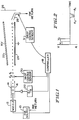
- Ink is supplied under pressure from a source 10 to a nozzle 12.
- Stimulation energy is applied to the nozzle 12, usually by means of a piezo-electric device, to cause the ink stream issuing from the nozzle 12 to break up into a series of drops.
- the drops pass through a charge tunnel formed by a pair of plates 14 and 16 or a horseshoe or annular shaped tunnel, as may be desired.
- the tunnel applies a charge to selected drops in response to signals from a programmable controller (PC) 18 via a digital to analog converter 20.
- the programmable controller 18 includes a memory. After leaving the tunnel the drop stream next passes through a pair of high voltage deflection plates 22 and 24 which deflect the charged drops onto a substrate 26 to be marked. Uncharged drops pass into a catcher 28 and are returned to the ink source 10 for further use.
- a drop charge detector 30 or 31, depending upon which of the methods described hereafter is employed, is provided for this purpose.
- the outputs of the detector 30 or 31 is supplied to the programmable controller 18.
- the charge on a drop breaking off from the ink stream in the tunnel 14 is a function of the capacitive and resistive coupling of the unbroken ink stream to the charge tunnel and is also a function of the capacitive coupling of the break-off drop to the charged drops preceding it. Consequently, the charge on the stream and on the break-off drop due to capacitive and resistive coupling is proportional to the potential on the charge tunnel minus a fraction of the charge on the drop preceding the break-off drop by one drop time (approximately in the range of 7% to 20%), a smaller fraction of the charge on the drop preceding it by two drop times (approximately in the range of 1% to 4%), and so on.
- induction fractions are sometimes referred to as “induction fractions” and the reduction in charge as “induction loss”.
- This drop charge induction phenomenon is corrected for by initial drop position compensation. If field conditions are different from initial compensation conditions, such that the induction effects change, an adjustment to the compensation data is necessary. For example, the charging voltage values stored in the memory of the programmable controller 18 may be increased for drops following charged drops to negate the effect of the induction loss.
- FIGS 3 and 4 illustrate the problem.
- FIG 3 shows print results with proper alignment while FIG 4 illustrates the degradation in quality due to misalignment.
- the present invention provides an automatic system which adjusts the charging voltages for changes in the induction fractions for each particular machine.
- the advantage is that is avoids the need for strict mechanical tolerances on the nozzle/charge tunnel system and/or adjustment of the charge tunnel. The necessary corrections can be obtained during a print quality calibration procedure when the printer is turned on.
- the inductive fractions can be determined. For example, a charged drop can be separated from induced charge drops by a deflection scheme. The induced charge drops carry a much lower, opposite, charge and therefore are easy to separate from the charged drop. The ratio of the stream charge measured without deflecting the charged drop to that measured when the drop is deflected gives the sum of the induction fractions.
- various voltage charge patterns can be applied to the drops. These patterns can be detected by a downstream drop charge sensor to measure the value of the inductive fractions.
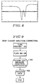
- a small capacitive pickup associated with detector 30 can distinguish individual drop charge amplitudes as they pass by.
- two drops charged with identical charging voltages show a difference in the pickup output amplitude.
- the second drop will produce a lower amplitude due to the first order inductive fraction effect.
- the voltages can then be adjusted until the pickup amplitudes are equal.
- the difference in charging voltages can be used to determine the 1st order inductive fraction.
- the charging electrode is the positive plate of a capacitor and the ink stream is the negative plate.
- V 0 V 1 - V 0 *I 1
- I 1 V 1 /V 0 - 1
- V 0 300 volts and V 1 were 350 volts when equal charges were detected at the sensor
- FIG 2 illustrates this approach.
- the detected charge signals A 1 and A 2 are equal the voltages used to charge them, V 1 and V 2 , are the values used to determine the induction coefficients. All subsequent voltages can be adjusted via the processing scheme (FIG 14) and stored in the PC memory. All orders beyond the second order are quite small and can be neglected (see FIG 8A). Indeed, even the second order can often be neglected with good results.
- induction fractions are I 1 , I 2 , ... I n respectively.
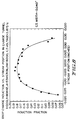
- I 1 and I 2 are 7% to 20% and 1% to 4% respectively. All other I's may be assumed to be negligible, as can be seen from FIG 8A.
- This figure is a plot of induction fraction versus coefficient order for a typical ink jet printer. The upper curve represents center stream alignment. The lower curve is off center relative to the plates. In both cases the drop off in the fraction is such that higher orders (those above second order) may be safely ignored.
- the capacitance between any two objects is determined by the geometry of the system (apart from a constant related to the materials in the system).
- C has its minimum value when the stream is centered in the charge tunnel and increases as the stream is moved away from this position.
- a change in C is not troublesome (provided drop spacing is held constant), since all charges are increased (or decreased) by the same factor. This is equivalent to a change in the gain of the charge amplifier.
- print quality is unaffected by minor gain changes as a result of proportional changes in capacitance.
- drop-to-drop spacing changes are effectively changes in the geometry so it follows that the inter-capacitance between all drops increases if the drop-to-drop spacing decreases and vice versa.
- This change causes I(1), I(2), ...I(n) to change in a manner similar to the ink stream misalignment or charge tunnel mis-dimensioning effect.
- I(1), I(2), ...I(n) causes I(1), I(2), ...I(n) to change in a manner similar to the ink stream misalignment or charge tunnel mis-dimensioning effect.
- I 1 induction fraction
- a Faraday cup Monroe Electronics Model 253 Nanocoulomb Meter - a static charge measurement device. Approximately 1,000 charged drops, each separated by four grounded drops, were deflected into the cup producing a total charge accumulation of approximately 2 nanoCoulombs, an amount within the measurement capability of the device. By counting the number of deflected drops and noting the total charge measured, it was possible to calculate q, the charge on each drop.
- FIG 7 is a plot showing the difference in charge between q 0 (the adjacent or leading drop) and q 1 (the break-off or trailing drop) for various stream positions within the charge tunnel.
- FIG 8 is a plot of I 1 versus stream position. As can be seen from the figures, the induction fraction, I 1 decreases rapidly as the stream approaches either plate of the tunnel.
- FIG 3 is a print sample taken with a properly aligned charge tunnel of correct width. This sample exhibits correct drop placement.
- FIG 4 shows print samples exhibiting poor quality due to an improperly aligned charge tunnel.
- FIG 5 is a print sample taken with the same tunnel misalignment as that in FIG 4 but with mathematically adjusted voltage data. This sample indicates the feasibility of this type of calibration procedure.
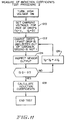
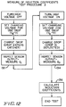
- FIGS 9 - 14 there is disclosed the method for making the drop charge induction corrections.
- FIG 9 shows the general procedure which is applicable to all of the specific procedures described in connection with FIGS 10 - 13.
- the printer is turned on, as is the ink supply.
- a measurement is then performed, step 100, to determine the correct induction factors.
- the test performed varies depending upon which of the procedures disclosed herein is utilized.
- the data obtained is processed to produce corrected induction factors, step 102 after which the ink jet printer is ready for use.
- the data processing step 102 is described in connection with FIG 14 hereafter.
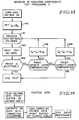
- a first and preferred measurement procedure is disclosed.
- the high voltage to the deflection electrodes 22 and 24 is turned off, step 104.
- Equal charge voltages are applied to the tunnel electrodes 14 and 16 (step 106).
- the pair of drops are then charged and the drop charge detected by the detector 30 and its capacitive pickup, step 108.
- a second test procedure according to the invention is disclosed.
- the deflection plates are turned on, rather than off.
- the drop stream passes to the catcher.
- a sensor 31 located proximate to the ink catcher 28 is employed to detect the induced charge on the drop stream when it enters the catcher, step 124.
- step 132 The charged drop and drops on which it induces charges enter the catcher 28 and the total charge Q 1 is sensed by a detector 31 located proximate thereto, step 132.
- Test pattern voltages are then printed, step 141 and a determination is made by the operator whether the print is acceptable, step 144. If the ⁇ values result in overcompensation an adjustment is made, step 146. If under-compensation is detected an opposite adjustment is made, step 148. New test pattern voltages are then computed and a further pattern printed until acceptable print is obtained.
- step 140 the selection of an initial I n can be determined by any of the test procedures described in connection with FIGS 10 - 12 (each of which generates a I n ) or using factory settings ( ⁇ n ) as the seed and altering the values based on the results of the print test at step 142.
- the voltage data used to charge the plates 14 and 16 is stored in the memory of the programmable controller 18, usually in the form of a print buffer or voltage table.
- the data consists of a series of voltage values V 1 through V n .
- the printer comes from the factory with a set of voltage data in the table as the default values.
- a correction algorithm is employed.
- the values can be read into the controller on the fly and altered by the correction algorithm to produce corrected voltages for the charge tunnel.
- ⁇ n V n +(I 1 - ⁇ 1 )V n-1 + ⁇ (I 2 - ⁇ 2 ) - ⁇ 1 (I 1 - ⁇ 1 ) ⁇ V n-2
- ⁇ are corrected charging voltages
- ⁇ n are nominal values of the induction coefficients
- I n are actual values of induction coefficients as measured during the correction procedure.
- this equation is a second order correction. It is unlikely that a higher order correction would be required, although it can be accomplished by simply extending the series. In practice, a first order correction will be satisfactory for many purposes. In that case, the bracketed term is set to zero.
- the corrected voltage data ⁇ 1 through ⁇ n is stored in the voltage table and thereafter employed for printing. With these corrections, the improved printing illustrated in FIG 5 is obtained, even with charge tunnel misalignment.
Landscapes
- Particle Formation And Scattering Control In Inkjet Printers (AREA)
Description
- This invention relates to ink jet printers. More particularly it relates to ink jet printers of the type which form drops from a stream or several streams of ink, charge the drops and then deflect them onto a substrate to be marked. Such devices are well known in this art.
- Printing distortions have long been a problem with ink jet printers. Many of the causes are well known and include variation in ink quality, improper jet nozzle drive and improper proximity to the substrate. Recent research has indicated another important cause of distortion exists, which emanates from non-proportional changes in charging.
- Ink jet printing devices typically employ a programmable controller (PC) to set the various parameters necessary for proper operation. The PC includes a memory containing drop position compensation data for each graphic or alpha-numeric character to be printed. This data is created at the factory when the jet stream is carefully centered within the charging electrode. This data is used on all ink jet machines of the same model. Actual printers, for one reason or another, tend to have their ink streams misaligned within the electrode or have their drop spacing or electrode width somewhat out of specification. Indeed, mechanical stream alignment is difficult to accurately achieve in the field. If the stream is not well aligned distortions in ink jet printing will occur such as those illustrated in FIG 4. These problems are particularly evident when every drop printing is employed, and are evident to a lesser extent with every other drop printing. The present invention provides various ways by which these problems can be solved and the resulting distortions corrected. In addition, the present invention can compensate for changes in electrical resistivity in the ink. This invention is particularly important for use in multi-jet printers to maintain consistent quality throughout an array of jets.
- It is accordingly an object of the invention to provide a method and apparatus for correcting, at least in part, printing distortions which occur in ink jet printers due to non-proportional changes in charging of the drops.
- Another object of the invention is to provide improved ink jet printing of characters on a substrate by adjusting the charge voltages to accommodate machine to machine variations.
- A further object of the invention is to provide an automatic compensation method for field calibrating ink jet printers to maintain high print quality. These and other objects of the invention will be apparent from the remaining portion of the specification.
- In a first aspect this invention provides a method for field adjusting the calibrated charge tunnel voltages, Vn of an ink jet printer to reduce printing distortion characterised by the method comprising the steps of:
- a) measuring the actual values of the induction coefficients, Im for said printer;
- b) altering the voltages Vn by a factor related to the difference between βm, the calibrated induction coefficients, and Im to obtain adjusted voltages Φn;
- c) employing the adjusted voltages Φn for printing.
- By measuring the actual values of the induction coefficients Im for the printer and altering the voltages Vn to correct for differences between the actual values and the calibrated induction coefficient values the distortions resulting from non-proportional changes in drop charging can be corrected for.
- In a second aspect this invention provides an ink jet printer including an ink supply, a nozzle, stimulation means acting on the nozzle to create a stream of ink drops, a charge tunnel to which voltages Vn are applied by a programmable controller thereby to charge selected drops in said stream, deflection plates for deflecting charged drops and an ink catcher for receiving uncharged drops, characterised by also comprising:
a system for field adjustment of calibrated charge tunnel voltages Vn to reduce printing distortions of a printer, the system including; means for measuring the actual value of the induction coefficients, Im for said printer; and means for altering the calibrated voltages Vn by a factor related to the difference between βm, the factory calibrated induction coefficients, and Im to obtain adjusted voltages Φn; said programmable controller employing the adjusted voltages Φn for printing. - Ink jet printer systems employing the invention will now be described by way of example only with reference to the accompanying diagrammatic figures in which;
- Figure 1 is a schematic diagram of a typical ink jet printer system suitable for use with the present invention,
- Figure 2 is a waveform diagram useful in understanding the invention,
- Figure 3 is a reproduction of alpha-numeric characters produced by a properly aligned charge tunnel,
- Figure 4 is a reproduction of alpha-numeric characters produced by a misaligned charge tunnel,
- Figure 5 is a reproduction of alpha-numeric characters produced by a misaligned charge tunnel adjusted according to the invention,
- Figure 6 is a waveform showing the effect of capacitive coupling between two adjacent charged ink drops,
- Figure 7 is a plot of drop charge versus stream position,
- Figure 8 is a plot of drop charge induction versus stream position,
- Figure 8A is a curve fit plot of induction fraction, In versus coefficient order, n, and
- Figures 9 to 14 are flow diagrams useful in explaining the implementation of the invention for a programmable controller.
- Referring to FIG 1, a typical ink jet printer arrangement is illustrated. Ink is supplied under pressure from a
source 10 to anozzle 12. Stimulation energy is applied to thenozzle 12, usually by means of a piezo-electric device, to cause the ink stream issuing from thenozzle 12 to break up into a series of drops. The drops pass through a charge tunnel formed by a pair ofplates analog converter 20. Theprogrammable controller 18 includes a memory. After leaving the tunnel the drop stream next passes through a pair of highvoltage deflection plates 22 and 24 which deflect the charged drops onto asubstrate 26 to be marked. Uncharged drops pass into acatcher 28 and are returned to theink source 10 for further use. - For purposes of explaining and practicing the present invention, it is desirable to detect the charge on the drops after they leave the charge tunnel. A
drop charge detector 30 or 31, depending upon which of the methods described hereafter is employed, is provided for this purpose. The outputs of thedetector 30 or 31 is supplied to theprogrammable controller 18. - The charge on a drop breaking off from the ink stream in the
tunnel 14 is a function of the capacitive and resistive coupling of the unbroken ink stream to the charge tunnel and is also a function of the capacitive coupling of the break-off drop to the charged drops preceding it. Consequently, the charge on the stream and on the break-off drop due to capacitive and resistive coupling is proportional to the potential on the charge tunnel minus a fraction of the charge on the drop preceding the break-off drop by one drop time (approximately in the range of 7% to 20%), a smaller fraction of the charge on the drop preceding it by two drop times (approximately in the range of 1% to 4%), and so on. These fractions are sometimes referred to as "induction fractions" and the reduction in charge as "induction loss". This drop charge induction phenomenon is corrected for by initial drop position compensation. If field conditions are different from initial compensation conditions, such that the induction effects change, an adjustment to the compensation data is necessary. For example, the charging voltage values stored in the memory of theprogrammable controller 18 may be increased for drops following charged drops to negate the effect of the induction loss. - Print quality for fonts utilizing every drop is significantly degraded if the charge tunnel is not centered about the stream, if the charge tunnel width is incorrect or if the drop spacing is incorrect. This is because the induction fractions differ from those used to produce the drop charge compensation values stored in the PC memory. As a result, certain drops are charged incorrectly (i.e. drops following charged drops usually receive incorrect charge) causing print quality difficulties. FIGS 3 and 4 illustrate the problem. FIG 3 shows print results with proper alignment while FIG 4 illustrates the degradation in quality due to misalignment.
- At the present time, to ensure good print quality when printing with every drop, it is necessary to demand very accurate drop spacing and charge tunnel width and orientation about the stream. The second and third of these requirements are difficult to achieve in practice due to tolerance errors in the nozzle/charge tunnel system. As a result, it has been necessary to design an adjustable charge tunnel which can be field adjusted relative to the stream.
- The present invention provides an automatic system which adjusts the charging voltages for changes in the induction fractions for each particular machine. The advantage is that is avoids the need for strict mechanical tolerances on the nozzle/charge tunnel system and/or adjustment of the charge tunnel. The necessary corrections can be obtained during a print quality calibration procedure when the printer is turned on.
- There are various ways that the inductive fractions can be determined. For example, a charged drop can be separated from induced charge drops by a deflection scheme. The induced charge drops carry a much lower, opposite, charge and therefore are easy to separate from the charged drop. The ratio of the stream charge measured without deflecting the charged drop to that measured when the drop is deflected gives the sum of the induction fractions.
- Preferably however, during start-up, before the deflection voltage to
plates 22 and 24 is turned on, various voltage charge patterns can be applied to the drops. These patterns can be detected by a downstream drop charge sensor to measure the value of the inductive fractions. A small capacitive pickup associated withdetector 30 can distinguish individual drop charge amplitudes as they pass by. In FIG 6 two drops charged with identical charging voltages show a difference in the pickup output amplitude. The second drop will produce a lower amplitude due to the first order inductive fraction effect. The voltages can then be adjusted until the pickup amplitudes are equal. The difference in charging voltages can be used to determine the 1st order inductive fraction. In the present instance, the charging electrode is the positive plate of a capacitor and the ink stream is the negative plate. This "negative plate" is connected to ground through the conductive ink. The positive or higher potential is placed on the charging electrode.
Thus:


Similarly,
- Requiring that


- Once the first order inductive fraction is known the higher order fractions can be empirically determined. The compensation data in the PC memory can then be updated. This will optimize the compensation data which in turn will optimize the quality of printing. FIG 2 illustrates this approach. When the detected charge signals A1 and A2 are equal the voltages used to charge them, V1 and V2, are the values used to determine the induction coefficients. All subsequent voltages can be adjusted via the processing scheme (FIG 14) and stored in the PC memory. All orders beyond the second order are quite small and can be neglected (see FIG 8A). Indeed, even the second order can often be neglected with good results.
- Returning, somewhat more rigorously, to the physics of the phenomena, the charge on the bream-off drop is reduced by a fraction of the charge on its immediate predecessor and by a smaller fraction of the charge on the drop preceding it by two drop times and so on. These induction fractions (sometimes referred to as inductive coefficients) are I1, I2, ... In respectively. In a typical system, approximate values for I1 and I2 are 7% to 20% and 1% to 4% respectively. All other I's may be assumed to be negligible, as can be seen from FIG 8A. This figure is a plot of induction fraction versus coefficient order for a typical ink jet printer. The upper curve represents center stream alignment. The lower curve is off center relative to the plates. In both cases the drop off in the fraction is such that higher orders (those above second order) may be safely ignored.
- For illustrative purposes, it is sufficient to consider only the break-off drop (the drop being charged) and its immediate predecessor. The charge, q1, on this drop can then be written as follows:


equation 1 we have:


- In order to perceive the cause of the print quality problems shown in FIG 4, it is necessary to determine what happens to the quantities in
equation 3 when the stream is moved away from the charge tunnel axis. Remember
- The capacitance between any two objects is determined by the geometry of the system (apart from a constant related to the materials in the system). In a jet printer, C has its minimum value when the stream is centered in the charge tunnel and increases as the stream is moved away from this position. By itself, a change in C is not troublesome (provided drop spacing is held constant), since all charges are increased (or decreased) by the same factor. This is equivalent to a change in the gain of the charge amplifier. In general, print quality is unaffected by minor gain changes as a result of proportional changes in capacitance.
- Similarly, drop-to-drop spacing changes are effectively changes in the geometry so it follows that the inter-capacitance between all drops increases if the drop-to-drop spacing decreases and vice versa. This change causes I(1), I(2), ...I(n) to change in a manner similar to the ink stream misalignment or charge tunnel mis-dimensioning effect. As an example, if the drop-to-drop spacing is out of specification by 5%, an approximate 5% change in I(1) will be observed. This change will not only be present in I(1) but will also be reflected in I(2)... I(n).
- To summarize, stream misalignment within the charge tunnel, electrode spacing deviations or inter-drop spacing errors cause non-proportional effects on I1.....In. This can be seen by examining equation (1) and nothing that I1's effect is additive.
- It is possible to measure the induction fraction, I1, as a function of stream position within the charge tunnel. For this purpose an experiment was performed using a 0.040" gap charge tunnel. Single drops charged to 287.5 volts were deflected into a Faraday cup (Monroe Electronics Model 253 Nanocoulomb Meter - a static charge measurement device). Approximately 1,000 charged drops, each separated by four grounded drops, were deflected into the cup producing a total charge accumulation of approximately 2 nanoCoulombs, an amount within the measurement capability of the device. By counting the number of deflected drops and noting the total charge measured, it was possible to calculate q, the charge on each drop.
- Next, in a similar experiment, approximately 1,000 pairs of charged drops, each pair separated by 4 grounded drops, were deflected into the cup, producing approximately 4 nanoCoulombs of charge. By counting the number of deflected pairs and noting the total charge measured, it was possible to calculate the sum of the charges on the first and second drops of the pair (adjacent drop and break-ff drop),


- FIG 3 is a print sample taken with a properly aligned charge tunnel of correct width. This sample exhibits correct drop placement. In comparison, FIG 4 shows print samples exhibiting poor quality due to an improperly aligned charge tunnel. As detailed hereafter, according to the invention it is possible to mathematically adjust the charging voltages for a change in the drop induction fraction due to tunnel misalignment, out of specification tunnel width or drop spacing. The process adjusts the voltages by small amounts until the voltage data correctly compensates for the drop induction effect.
- FIG 5 is a print sample taken with the same tunnel misalignment as that in FIG 4 but with mathematically adjusted voltage data. This sample indicates the feasibility of this type of calibration procedure.
- Referring to FIGS 9 - 14 there is disclosed the method for making the drop charge induction corrections. FIG 9 shows the general procedure which is applicable to all of the specific procedures described in connection with FIGS 10 - 13. At start-up, the printer is turned on, as is the ink supply. A measurement is then performed,
step 100, to determine the correct induction factors. The test performed varies depending upon which of the procedures disclosed herein is utilized. After completing the test, the data obtained is processed to produce corrected induction factors,step 102 after which the ink jet printer is ready for use. Thedata processing step 102 is described in connection with FIG 14 hereafter. - Referring to FIG 10 a first and preferred measurement procedure is disclosed. According to this procedure, the high voltage to the
deflection electrodes 22 and 24 is turned off,step 104. Equal charge voltages are applied to thetunnel electrodes 14 and 16 (step 106). The pair of drops are then charged and the drop charge detected by thedetector 30 and its capacitive pickup,step 108. The charging voltage for the trailing drop, V2 is incremented, step 112 and the process repeated until the condition q1 = q2 is satisfied (step 109). The induction coefficients are calculated atstep 110 from the equation: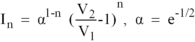
- Referring to FIG 11, a second test procedure according to the invention is disclosed. In this procedure, the deflection plates are turned on, rather than off. The charging voltages for a drop pair d1 and d2 are set at


step 122. The drop stream passes to the catcher. A sensor 31 located proximate to theink catcher 28 is employed to detect the induced charge on the drop stream when it enters the catcher,step 124. The controller then determines the magnitude of the charge, Q (
step 126. When Q = 0 the induction coefficients are calculated, step 128 using the formula:
catcher 28 and the total charge Q1 is sensed by a detector 31 located proximate thereto,step 132. The process is then repeated with the high voltage plates turned on (thus deflecting the first drop) and the total charge Q2 detected by the sensor is again determined,step 134. From this information the induction coefficients can be calculated, step 136 using the formula:
step 140. Test pattern voltages are then printed,step 141 and a determination is made by the operator whether the print is acceptable,step 144. If the β values result in overcompensation an adjustment is made,step 146. If under-compensation is detected an opposite adjustment is made,step 148. New test pattern voltages are then computed and a further pattern printed until acceptable print is obtained. - It will be recognized that
step 140, the selection of an initial In can be determined by any of the test procedures described in connection with FIGS 10 - 12 (each of which generates a In) or using factory settings (βn) as the seed and altering the values based on the results of the print test atstep 142. - Referring to FIG 14, the sequence for processing the test pattern voltages is illustrated. In the preferred embodiment the voltage data used to charge the
plates programmable controller 18, usually in the form of a print buffer or voltage table. The data consists of a series of voltage values V1 through Vn. The printer comes from the factory with a set of voltage data in the table as the default values. In order to alter the values in the table they are read in by the controller and a correction algorithm is employed. Alternatively, the values can be read into the controller on the fly and altered by the correction algorithm to produce corrected voltages for the charge tunnel. The preferred formula is:
- It should be noted that this equation is a second order correction. It is unlikely that a higher order correction would be required, although it can be accomplished by simply extending the series. In practice, a first order correction will be satisfactory for many purposes. In that case, the bracketed term is set to zero. After the correction algorithm is used, the corrected voltage data Φ1 through Φn is stored in the voltage table and thereafter employed for printing. With these corrections, the improved printing illustrated in FIG 5 is obtained, even with charge tunnel misalignment.
- While preferred embodiments of the present invention have been illustrated and described, it will be understood by those of ordinary skill in the art that changes and modifications can be made without departing from the invention as defined in the appended claims. Various features of the present invention are set forth in the following claims.
Claims (17)
- A method for field adjusting the calibrated charge tunnel voltages, Vn of an ink jet printer to reduce printing distortion characterised by the method comprising the steps of:a) measuring the actual values of the induction coefficients, Im for said printer;b) altering the voltages Vn by a factor related to the difference between βm, the calibrated induction coefficients, and Im to obtain adjusted voltages Φn;c) employing the adjusted voltages Φn for printing.
- A method according to Claim 1 and further characterised by the voltages Vn being altered according to the formula;

- A method according to Claim 1 and further characterised by the voltages Vn being altered according to the formula:

- A method according to any preceding Claim and further characterised by the voltages Vn being stored in a memory element associated with said printer in the form of a default voltage table and the method also including the steps of:
reading the voltages Vn from said table to permit alteration;
storing the adjusted voltages Φn in said memory element in a corrected voltage table;
printing from the corrected voltage table rather than the default voltage table. - A method according to any preceding Claim and further characterised by the step of measuring the induction coefficients In including the substeps of:i) applying voltages V1 and V2, V2 initially being equal to V1, to a pair of test drops d1 and d2 respectively to induce charges q1 and q2 on said drops;ii) measuring the induced charges q1 and q2;iii) incrementing V2 and repeating steps i) and ii) until
 iv) calculating the actual induction coefficients, Im, using the values of V1 and V2 when
- A method according to Claim 5 and further characterised by the step of calculating In employing the formula:

- A method according to any one of Claims 1 to 4 and further characterised by the step of measuring the induction coefficients In including the substeps of:i) applying voltages V1 and V2, V2 initially being zero, to a pair of test drops d1 and d2 in a drop stream to induce charges q1 and q2 on said drops;ii) electrostatically deflecting the drop d1 out of the path of said drop stream, the remaining drops in said stream, including d2, being received in an ink catcher;iii) measuring the drop stream charge Q, where
 iv) incrementing V2 and repeating steps i), ii) and iii) until Q = 0;v) calculating the actual induction coefficients In using the values V1 and V2 when Q = 0.
 - A method according to Claim 7 and further characterised by the step of calculating In employing the formula:

- A method according to any one of Claims 1 to 4 and further characterised by the step of measuring the induction coefficients In including the substeps of:i) applying a voltage V to a first drop in a drop stream directed at an ink catcher to apply a charge q1 to said first drop and to induce charges q2, q3 ...qn on succeeding drops;ii) measuring the stream charge Q1 where
 iii) repeating step i);iv) electrostatically deflecting the first drop out of the drop stream path, the remaining drops in said stream passing to the catcher;v) measuring the drop stream charge Q2, where
 vi) calculating the actual induction coefficients In using the formula:
- An ink jet printer including an ink supply (10), a nozzle (12), stimulation means acting on the nozzle to create a stream of ink drops, a charge tunnel (14, 16) to which voltages Vn are applied by a programmable controller (18) thereby to charge selected drops in said stream, deflection plates (22, 24) for deflecting charged drops and an ink catcher (28)for receiving uncharged drops, characterised by also comprising:
a system for field adjustment of calibrated charge tunnel voltages Vn to reduce printing distortions of a printer, the system including; means for measuring the actual value of the induction coefficients, Im for said printer; and means for altering the calibrated voltages Vn by a factor related to the difference between βm, the factory calibrated induction coefficients, and Im to obtain adjusted voltages Φn; said programmable controller employing the adjusted voltages Φn for printing. - A printer according to Claim 10 and further characterised by the voltages Vn being altered according to the formula:

- A printer according to Claim 10 or Claim 11 and further characterised by the voltages Vn and Φn being stored in a memory element associated with said printer in the form of a default voltage table and a corrected voltage table;
said controller printing from the corrected voltage table rather than the default voltage table. - A printer according to any one of Claims 10 to 12 and further characterised by the voltages Vn being altered according to the formula:

- A printer according to any one of Claims 10 to 13 and further characterised by the means for measuring including:
a drop charge sensor positioned to detect the charges on drops in said stream, the output of said sensor being provided to said means for altering. - A printer according to Claim 14 and further characterised by said sensor being positioned between said charge tunnel and said deflection plates.
- A printer according to Claim 14 and further characterised by said sensor being positioned in proximity to the ink catcher.
- A printer according to any one of Claims 10 et 16 and further characterised by the means for altering including said programmable controller which receives the value Im and βm and calculates the adjusted voltages, Φn according to the formula:

Applications Claiming Priority (2)
| Application Number | Priority Date | Filing Date | Title |
|---|---|---|---|
| US840161 | 1992-02-24 | ||
| US07/840,161 US5420624A (en) | 1992-02-24 | 1992-02-24 | Method and apparatus for correcting printing distortions in an ink jet printer |
Publications (3)
| Publication Number | Publication Date |
|---|---|
| EP0558284A2 EP0558284A2 (en) | 1993-09-01 |
| EP0558284A3 EP0558284A3 (en) | 1994-01-05 |
| EP0558284B1 true EP0558284B1 (en) | 1996-07-03 |
Family
ID=25281604
Family Applications (1)
| Application Number | Title | Priority Date | Filing Date |
|---|---|---|---|
| EP93301348A Expired - Lifetime EP0558284B1 (en) | 1992-02-24 | 1993-02-24 | Method and apparatus for correcting printing distortions in an ink jet printer |
Country Status (5)
| Country | Link |
|---|---|
| US (1) | US5420624A (en) |
| EP (1) | EP0558284B1 (en) |
| JP (1) | JPH0691879A (en) |
| CA (1) | CA2090078A1 (en) |
| DE (1) | DE69303393T2 (en) |
Families Citing this family (13)
| Publication number | Priority date | Publication date | Assignee | Title |
|---|---|---|---|---|
| US5517216A (en) * | 1992-07-28 | 1996-05-14 | Videojet Systems International, Inc. | Ink jet printer employing time of flight control system for ink jet printers |
| DE69725914T2 (en) * | 1996-03-11 | 2004-11-04 | Fuji Photo Film Co., Ltd., Minami-Ashigara | Image generation process and system |
| NL1008973C2 (en) * | 1998-04-23 | 1999-10-26 | Stork Digital Imaging Bv | Method and apparatus for checking and / or correcting an alignment of an inkjet printer. |
| US6626513B2 (en) | 2001-07-18 | 2003-09-30 | Lexmark International, Inc. | Ink detection circuit and sensor for an ink jet printer |
| US6870934B2 (en) * | 2002-07-15 | 2005-03-22 | Visteon Global Technologies, Inc. | Audio loudspeaker detection using back-EMF sensing |
| CA2408108A1 (en) * | 2002-10-15 | 2004-04-15 | Adam I. Pinard | Printing fluid delivery system |
| KR20070042965A (en) * | 2004-06-17 | 2007-04-24 | 비디오제트 테크놀러지즈 인코포레이티드 | System for aligning the charging tunnel of inkjet printer |
| JP4810081B2 (en) * | 2004-09-27 | 2011-11-09 | キヤノン株式会社 | Apparatus and method for measuring toner charge amount distribution |
| US20090027460A1 (en) * | 2007-07-23 | 2009-01-29 | Paul Klinker | System for aligning a charge tunnel of an ink jet printer |
| FR2934809A1 (en) * | 2008-08-11 | 2010-02-12 | Imaje Sa | INJECTOR INJECTOR INK JET PRINTING DEVICE, AIR INJECTOR, AND LARGE-WIDE PRINT HEAD |
| FR2934810A1 (en) * | 2008-08-11 | 2010-02-12 | Imaje Sa | INKJET PRINTING DEVICE COMPRISING JET SPEED COMPENSATION |
| JP7154766B2 (en) * | 2018-01-15 | 2022-10-18 | 株式会社日立産機システム | Inkjet recording device |
| CN120462016B (en) * | 2025-07-11 | 2025-09-30 | 广安职业技术学院 | Calibration method for charging matrix of ink jet printer |
Family Cites Families (9)
| Publication number | Priority date | Publication date | Assignee | Title |
|---|---|---|---|---|
| IT1129356B (en) * | 1980-10-31 | 1986-06-04 | Olivetti Ing C Spa | SELECTIVE INK JET PRINTING DEVICE |
| JPS5686768A (en) * | 1979-12-18 | 1981-07-14 | Ricoh Co Ltd | Electric charge quantity control method in ink jet printing |
| US4395717A (en) * | 1980-03-07 | 1983-07-26 | Ricoh Company, Ltd. | Ink jet recording apparatus |
| JPS57207071A (en) * | 1981-06-17 | 1982-12-18 | Ricoh Co Ltd | Ink jet recorder |
| JPS5898260A (en) * | 1981-12-02 | 1983-06-11 | ゼロツクス・コ−ポレ−シヨン | Ink injection printer and method of charging ink drop |
| EP0086516B1 (en) * | 1982-02-11 | 1986-05-28 | Agfa-Gevaert N.V. | Xerographic copying apparatus |
| JPS6183046A (en) * | 1984-09-29 | 1986-04-26 | Minolta Camera Co Ltd | Ink jet recording apparatus capable of expression gradation |
| US4800396A (en) * | 1987-07-08 | 1989-01-24 | Hertz Carl H | Compensation method and device for ink droplet deviation of an ink jet |
| US4994821A (en) * | 1989-09-18 | 1991-02-19 | Eastman Kodak Company | Continuous ink jet printer apparatus having improved short detection construction |
-
1992
- 1992-02-24 US US07/840,161 patent/US5420624A/en not_active Expired - Fee Related
-
1993
- 1993-02-22 CA CA002090078A patent/CA2090078A1/en not_active Abandoned
- 1993-02-24 EP EP93301348A patent/EP0558284B1/en not_active Expired - Lifetime
- 1993-02-24 JP JP5035784A patent/JPH0691879A/en active Pending
- 1993-02-24 DE DE69303393T patent/DE69303393T2/en not_active Expired - Fee Related
Also Published As
| Publication number | Publication date |
|---|---|
| EP0558284A3 (en) | 1994-01-05 |
| DE69303393T2 (en) | 1996-10-31 |
| EP0558284A2 (en) | 1993-09-01 |
| US5420624A (en) | 1995-05-30 |
| CA2090078A1 (en) | 1993-08-25 |
| JPH0691879A (en) | 1994-04-05 |
| DE69303393D1 (en) | 1996-08-08 |
Similar Documents
| Publication | Publication Date | Title |
|---|---|---|
| US5420624A (en) | Method and apparatus for correcting printing distortions in an ink jet printer | |
| US3886564A (en) | Deflection sensors for ink jet printers | |
| US6464322B2 (en) | Ink jet printer and a process for compensating for mechanical defects in the ink jet printer | |
| EP1011976B1 (en) | Ink-jet printing apparatus and method | |
| EP0607419B1 (en) | Variable frequency ink jet printer | |
| EP0519708B1 (en) | Array jet velocity normalization | |
| US4800396A (en) | Compensation method and device for ink droplet deviation of an ink jet | |
| CA1143782A (en) | Scaling aerodynamic compensation in an ink jet printer | |
| CA1133568A (en) | Stitching method and apparatus for multiple nozzle ink jet printers | |
| US4490653A (en) | Deflection systems and ramp generators therefor | |
| US4484199A (en) | Method and apparatus for detecting failure of an ink jet printing device | |
| DE3532437A1 (en) | INK-JET PRINTER WITH CORRECTION OF DROP DROP SPACING | |
| EP0039772B1 (en) | Multinozzle ink jet printer and method of operating such a printer | |
| DE2611282A1 (en) | INKJET PEN | |
| US6550886B2 (en) | Ink jet printer capable of adjusting deflection amount in accordance with positional shift of head modules | |
| EP0744292B1 (en) | Method and apparatus for automatic setting of nozzle drive voltage in an ink jet printer | |
| US4636809A (en) | Ink catcher and drop charge sensing device | |
| US4638325A (en) | Ink jet filament length and stimulation amplitude assessment system | |
| US5844581A (en) | Electronic control for consistent ink jet images | |
| EP0036789A1 (en) | Liquid jet printing apparatus | |
| EP0013160B1 (en) | Method and apparatus for determining the applied voltage at which paschen breakdown occurs in electrography | |
| US5517216A (en) | Ink jet printer employing time of flight control system for ink jet printers | |
| EP0204773A4 (en) | Apparatus for monitoring and adjusting liquid jets in ink jet printers. | |
| JPH0789123A (en) | Correction of density irregularity in image forming apparatus |
Legal Events
| Date | Code | Title | Description |
|---|---|---|---|
| PUAI | Public reference made under article 153(3) epc to a published international application that has entered the european phase |
Free format text: ORIGINAL CODE: 0009012 |
|
| AK | Designated contracting states |
Kind code of ref document: A2 Designated state(s): CH DE ES FR GB IT LI NL SE |
|
| PUAL | Search report despatched |
Free format text: ORIGINAL CODE: 0009013 |
|
| AK | Designated contracting states |
Kind code of ref document: A3 Designated state(s): CH DE ES FR GB IT LI NL SE |
|
| 17P | Request for examination filed |
Effective date: 19940228 |
|
| 17Q | First examination report despatched |
Effective date: 19950707 |
|
| GRAH | Despatch of communication of intention to grant a patent |
Free format text: ORIGINAL CODE: EPIDOS IGRA |
|
| GRAA | (expected) grant |
Free format text: ORIGINAL CODE: 0009210 |
|
| AK | Designated contracting states |
Kind code of ref document: B1 Designated state(s): CH DE ES FR GB IT LI NL SE |
|
| PG25 | Lapsed in a contracting state [announced via postgrant information from national office to epo] |
Ref country code: NL Free format text: LAPSE BECAUSE OF FAILURE TO SUBMIT A TRANSLATION OF THE DESCRIPTION OR TO PAY THE FEE WITHIN THE PRESCRIBED TIME-LIMIT Effective date: 19960703 Ref country code: LI Effective date: 19960703 Ref country code: IT Free format text: LAPSE BECAUSE OF FAILURE TO SUBMIT A TRANSLATION OF THE DESCRIPTION OR TO PAY THE FEE WITHIN THE PRE;WARNING: LAPSES OF ITALIAN PATENTS WITH EFFECTIVE DATE BEFORE 2007 MAY HAVE OCCURRED AT ANY TIME BEFORE 2007. THE CORRECT EFFECTIVE DATE MAY BE DIFFERENT FROM THE ONE RECORDED.SCRIBED TIME-LIMIT Effective date: 19960703 Ref country code: ES Free format text: THE PATENT HAS BEEN ANNULLED BY A DECISION OF A NATIONAL AUTHORITY Effective date: 19960703 Ref country code: CH Effective date: 19960703 |
|
| REF | Corresponds to: |
Ref document number: 69303393 Country of ref document: DE Date of ref document: 19960808 |
|
| ET | Fr: translation filed | ||
| PG25 | Lapsed in a contracting state [announced via postgrant information from national office to epo] |
Ref country code: SE Effective date: 19961003 |
|
| NLV1 | Nl: lapsed or annulled due to failure to fulfill the requirements of art. 29p and 29m of the patents act | ||
| REG | Reference to a national code |
Ref country code: CH Ref legal event code: PL |
|
| PG25 | Lapsed in a contracting state [announced via postgrant information from national office to epo] |
Ref country code: GB Effective date: 19970224 |
|
| PLBE | No opposition filed within time limit |
Free format text: ORIGINAL CODE: 0009261 |
|
| STAA | Information on the status of an ep patent application or granted ep patent |
Free format text: STATUS: NO OPPOSITION FILED WITHIN TIME LIMIT |
|
| 26N | No opposition filed | ||
| GBPC | Gb: european patent ceased through non-payment of renewal fee |
Effective date: 19970224 |
|
| PG25 | Lapsed in a contracting state [announced via postgrant information from national office to epo] |
Ref country code: FR Effective date: 19971030 |
|
| PG25 | Lapsed in a contracting state [announced via postgrant information from national office to epo] |
Ref country code: DE Effective date: 19971101 |
|
| REG | Reference to a national code |
Ref country code: FR Ref legal event code: ST |