EP0744292B1 - Method and apparatus for automatic setting of nozzle drive voltage in an ink jet printer - Google Patents
Method and apparatus for automatic setting of nozzle drive voltage in an ink jet printer Download PDFInfo
- Publication number
- EP0744292B1 EP0744292B1 EP96303040A EP96303040A EP0744292B1 EP 0744292 B1 EP0744292 B1 EP 0744292B1 EP 96303040 A EP96303040 A EP 96303040A EP 96303040 A EP96303040 A EP 96303040A EP 0744292 B1 EP0744292 B1 EP 0744292B1
- Authority
- EP
- European Patent Office
- Prior art keywords
- drops
- nozzle drive
- nozzle
- determining
- stream
- Prior art date
- Legal status (The legal status is an assumption and is not a legal conclusion. Google has not performed a legal analysis and makes no representation as to the accuracy of the status listed.)
- Expired - Lifetime
Links
- 238000000034 method Methods 0.000 title claims description 25
- 238000012360 testing method Methods 0.000 claims description 33
- 238000007639 printing Methods 0.000 claims description 25
- 239000012530 fluid Substances 0.000 claims description 2
- 230000003252 repetitive effect Effects 0.000 claims description 2
- 239000000976 ink Substances 0.000 description 38
- 238000010586 diagram Methods 0.000 description 3
- 230000000638 stimulation Effects 0.000 description 3
- 239000000758 substrate Substances 0.000 description 3
- 230000001419 dependent effect Effects 0.000 description 2
- 230000002411 adverse Effects 0.000 description 1
- 230000002950 deficient Effects 0.000 description 1
- 238000001514 detection method Methods 0.000 description 1
- 230000000977 initiatory effect Effects 0.000 description 1
- 238000007641 inkjet printing Methods 0.000 description 1
- 238000005259 measurement Methods 0.000 description 1
- 238000011002 quantification Methods 0.000 description 1
- 238000005070 sampling Methods 0.000 description 1
- 238000000926 separation method Methods 0.000 description 1
- 239000007787 solid Substances 0.000 description 1
- 239000002904 solvent Substances 0.000 description 1
Images

Classifications
-
- B—PERFORMING OPERATIONS; TRANSPORTING
- B41—PRINTING; LINING MACHINES; TYPEWRITERS; STAMPS
- B41J—TYPEWRITERS; SELECTIVE PRINTING MECHANISMS, i.e. MECHANISMS PRINTING OTHERWISE THAN FROM A FORME; CORRECTION OF TYPOGRAPHICAL ERRORS
- B41J2/00—Typewriters or selective printing mechanisms characterised by the printing or marking process for which they are designed
- B41J2/005—Typewriters or selective printing mechanisms characterised by the printing or marking process for which they are designed characterised by bringing liquid or particles selectively into contact with a printing material
- B41J2/01—Ink jet
- B41J2/07—Ink jet characterised by jet control
- B41J2/12—Ink jet characterised by jet control testing or correcting charge or deflection
-
- B—PERFORMING OPERATIONS; TRANSPORTING
- B41—PRINTING; LINING MACHINES; TYPEWRITERS; STAMPS
- B41J—TYPEWRITERS; SELECTIVE PRINTING MECHANISMS, i.e. MECHANISMS PRINTING OTHERWISE THAN FROM A FORME; CORRECTION OF TYPOGRAPHICAL ERRORS
- B41J2/00—Typewriters or selective printing mechanisms characterised by the printing or marking process for which they are designed
- B41J2/005—Typewriters or selective printing mechanisms characterised by the printing or marking process for which they are designed characterised by bringing liquid or particles selectively into contact with a printing material
- B41J2/01—Ink jet
- B41J2/015—Ink jet characterised by the jet generation process
- B41J2/02—Ink jet characterised by the jet generation process generating a continuous ink jet
-
- B—PERFORMING OPERATIONS; TRANSPORTING
- B41—PRINTING; LINING MACHINES; TYPEWRITERS; STAMPS
- B41J—TYPEWRITERS; SELECTIVE PRINTING MECHANISMS, i.e. MECHANISMS PRINTING OTHERWISE THAN FROM A FORME; CORRECTION OF TYPOGRAPHICAL ERRORS
- B41J2/00—Typewriters or selective printing mechanisms characterised by the printing or marking process for which they are designed
- B41J2/005—Typewriters or selective printing mechanisms characterised by the printing or marking process for which they are designed characterised by bringing liquid or particles selectively into contact with a printing material
- B41J2/01—Ink jet
- B41J2/07—Ink jet characterised by jet control
- B41J2/075—Ink jet characterised by jet control for many-valued deflection
- B41J2/08—Ink jet characterised by jet control for many-valued deflection charge-control type
- B41J2/085—Charge means, e.g. electrodes
Definitions
- This invention relates to commercial and industrial ink jet printers of the type commonly used for marking of products. Such devices require high speed and high reliability and must operate in somewhat hostile environments in terms of temperature, service intervals and the like.
- an ink jet printer When an ink jet printer is being readied for use, it has been necessary to calibrate the printer for the particular characteristics of the ink and nozzle it is to use.
- certain characteristics of the printing operation For example, it is known to determine the infinite satellite condition and the foldback point of an ink drop stream.
- the former is a condition in which the small satellites which form between drops, neither forwardly nor rearwardly merge with the main drops.
- the foldback condition is an upper bound in which the break off point of the drops, relative to the nozzle, first reverses. The foldback condition is described more thoroughly in U.S. Patent No. 5,196,860.
- U.S. Patent No. 5,196,860 to Pickell et al. assigned to the present assignee, detects one or both of these points and then selects a predetermined nozzle drive voltage somewhere between the two bounds. It does not, however, directly determine the true bounds of the print window. It relies on factory data concerning the ink and the nozzle to calculate a voltage that is expected to lie within the print window.
- a method for accurately determining the print window for an ink jet printer characterised in that the method comprises the steps of:
- a method for accurately determining the print window for an ink jet printer characterised in that the method comprises the steps of:
- a third aspect of the present invention there is provided a method for determining the good printing range for a printer which employs a nozzle to project a stream of marking fluid under pressure toward a target, characterised in that the method comprises the steps of:
- an ink jet printer having an ink source, a nozzle assembly for creating an ink stream which breaks into drops, a drop charging electrode, deflection electrodes, an ink catcher for uncharged drops, characterised in that the ink jet printer further comprises:
- the present invention provides a method of automatically determining the actual nozzle drive "print window", that is, the range of nozzle drive voltages that provide substantially constant deflection of drops (i.e., desirable print quality) for a particular nozzle, ink type, font and stimulation voltage waveform combination.
- the nozzle operation is sampled and used to accurately determine the print window. It is possible therefore, for the first time, to test a printer whenever necessary, for example, upon installing a new nozzle or a different ink, thereby to positively determine the print window or range of nozzle drive values at which the printer can be operated to obtain good printing results.
- a predetermined voltage pattern for charging test drops is employed.
- the system measures the stream current in a stream of test drops deflected to a sensing electrode.
- the drop charging pattern is arranged so that uncharged drops follow each charged drop.
- satellites forwardly merge with the drop that they follow, thereby to ensure that the entire charge placed upon a drop at break off from the drop stream remains with the drop. If satellites do not forwardly merge or they merge rearwardly, the charge is redistributed and adversely affects the deflection of the drops. In either case, the charge from the non-forwardly merging satellite is not detected by the sensing electrode, and this reduces the current of the deflected drop stream detected by a current electrode.
- the print window is defined as the range of nozzle drive waveform voltages where a substantially constant, maximum stream current is detected.
- the calibration routine can be performed at set-up or whenever desired by an operator, for example, when a new nozzle or a different ink is to be used or a different font size is to be printed.
- the calibration routine may also be automatically called at suitable times when the printer is not required to print.
- the printer includes a print controller 10 of the type typically used in this industry.
- the controller 10 includes a micro-processor or similar device programmed to operate the ink jet printer according to the parameters set by the operator.
- the controller regulates the supply of ink from a source 12 via an ink supply conduit 14 to a nozzle 16.
- a stimulation voltage waveform or drive voltage waveform is applied to the nozzle, usually through a piezoelectric device 17, in a manner well known in this art at a frequency selected to cause break up into droplets of the stream of ink 18 ejected from the nozzle.
- the drop break off point is a function of the ink pressure, the nozzle diameter and the magnitude of the applied nozzle drive voltage, among other factors.
- the break off point occurs within a charge tunnel 20.
- Charged drops are thereafter deflected by a pair of deflection electrodes 22 in the course of travel toward a substrate to be marked (not shown). That is, drops which carry a charge are deflected onto the substrate while uncharged drops pass undeflected through the electrodes.
- the uncharged drops are directed toward a catcher 24 which returns the ink to a sump 26 and/or to the ink source 12 for reuse.
- a catcher 24 which returns the ink to a sump 26 and/or to the ink source 12 for reuse.
- Not shown, but typically included in a standard printer of this type are fresh ink reservoirs, solvent reservoirs and valves controlled by the controller 10 for maintaining the quality of the ink relatively constant during the course of the printing operation.
- the automatic nozzle setting function of the invention is accomplished by use of a sensing electrode 28 disposed at the point where the deflected drops would normally reach the substrate to be marked. Obviously, the sensing electrode is in place only during the period of time when the print window is being determined and is thereafter removed so that normal printing can occur.
- the sensing electrode 28 is connected to a current measuring circuit or device, such as an ammeter 30, or preferably a picoammeter. The current detected by the current measuring device is provided to the print controller 10 which uses this information to determine the print window in the manner described hereafter.
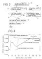
- print window illustrates plots of stream current versus nozzle drive voltage as detected by the sensing electrode 28 for three different nozzles.
- nozzle represented by the solid circles
- a maximum stream current of approximately seven nanoamps is maintained over nozzle drive voltages from twenty through forty-three.
- the print window (PW) or useful printing range for this particular nozzle, is extremely wide and good printing results can be obtained anywhere therein simply by setting the nozzle drive voltage to a value within this window, for example, thirty volts.
- the nozzle represented by the open circles has a print window beginning at approximately thirteen volts and terminating at approximately eighteen volts.
- the print window for this nozzle is much more limited. It is required, when using such a nozzle, to carefully and precisely set the nozzle drive voltage to a value within the rather narrow print window.
- Figure 2 shows a third nozzle, which may be considered, for present purposes, to be defective. It is illustrated by the waveform carrying the triangular markers. It can be seen that this nozzle has a peak stream current at approximately thirteen volts, but that it rises to and falls from that value so rapidly that there is no effective print window.
- the current of the test drops which have been charged is measured while incrementing the nozzle drive voltage from a minimum value or decrementing the nozzle drive voltage from a maximum value.
- the print window is accurately determined by recording the stream current versus nozzle drive voltage to determine the voltage range where stream current remains near its maximum value. This is the print window or good printing region for any particular nozzle, ink, and font in most ink jet printers. The reason for this can be understood with reference to Figure 5.
- Figure 5 illustrates the manner in which the stream of ink 18 breaks up into drops 42 and satellites 44. The breakup must occur within the charge tunnel 20 in order for the drops to be properly charged.
- the next issue is whether the satellites 44 are infinite satellites, that is, they remain interleaved between the drops 42 or whether they merge forwardly or rearwardly with the drops 42.
- the motion of the satellites 44 is a function of the nozzle drive voltage, but is also charge dependent.
- the satellites are simply a small trailing portion of a drop which breaks off therefrom during or after the separation process within the charge tunnel and that in order for the full charge to be detected, each satellite must recombine with its "parent" drop.
- each charged drop is separated by at least one and preferably several guard drops which carry relatively no charge.
- the satellites are forwardly merging the total charge induced by the charge tunnel will be present on a charged drop when it reaches the sensing electrode 28 in Figure 1.
- the charged drops which are deflected to the sensing electrode 28 will have a lower charge than would otherwise be the case.
- the upper and lower bounds of the print window are a function of the nozzle drive voltage required to cause the satellites to forwardly merge, although the upper bound of the print window is also charge dependent. If a high charge is applied to the drops, electrostatic repulsion begins to overcome the forward momentum of the satellites, thus reducing the width of the print window. Increased charges are used for increased drop deflection to print large characters.
- Figure 6 illustrates that the print window for drops charged at 300 volts is markedly smaller than the print window for drops charged at 150 volts.
- the present invention is a significant improvement over the prior art because it measures the actual print window using a particular charge level, ink type and nozzle, thereby precisely determining the good printing range.
- Prior methods which only estimate the print window from a determination of the foldback voltage, do not compensate for these conditions resulting in the need for manual readjustments.
- Figure 3 is a software flow diagram illustrating the manner in which the print controller 10, preferably a microprocessor based device, is programmed to obtain the necessary data.
- the nozzle drive voltage applied to nozzle 16 is set to a predetermined value.
- the predetermined value will be a voltage greater than the foldback value if the data is to be taken by decrementing the nozzle drive voltage or it will be a very small value, at or above the infinite satellite voltage, if the data will be taken by incrementing the nozzle drive.
- the infinite satellite condition and the foldback condition can be easily determined automatically or by the operator.
- the controller causes a set of test drops to be generated in a specified pattern wherein a charge drop is separated by at least one and preferably several, uncharged guard drops.
- the sensing electrode 28 is placed in a path to intercept the charged drops which are deflected by the high voltage electrode 22 and to route the resulting current to an ammeter 30 for quantification.
- the deflected jet stream current is measured by the ammeter 30.
- a check is made to determine if the subroutine should terminate because it has reached the end of the print window. If this is the first time through, the answer will be "no" and the software branches to 56 where it stores the data on the stream current and nozzle drive voltage magnitudes.
- the nozzle drive is then decremented at 58 from its high initial value (or incremented if the initial value is below the print window) and steps 52 and 54 are repeated to obtain several more data points.
- a sufficient number of data points should be taken in order to provide a clear measurement of the print window.
- the program detects the low end of the print window by virtue of the fact that the magnitude of the stream current has fallen markedly from its maximum value.
- this feature indicates that the nozzle is no longer being driven sufficiently to cause the satellites to forwardly merge.
- this feature indicates that the upper bound has been reached.
- data sampling terminates and the program branches to 60 for calculation of the print window. This is done using standard data handling techniques whereby the data collected is converted into a set of data points on a stream current versus nozzle drive graph as shown in Figure 2. This information can be presented to the operator on a video display or printed out as a table of values. The data, once obtained, is used to set the nozzle drive as indicated at 62 either automatically by selecting a point within the mid-range of the print window or manually should the operator of the printing device prefer. The set-up routine then ends.
- the sensing electrode 28 Prior to initiating printing, the sensing electrode 28 is removed from the path of the charged drops. Whenever the parameters of the printer change as, for example, a new nozzle is used, a different ink is employed or a different font size is selected, the set-up routine of Figure 3 may be initiated to ensure that the nozzle drive voltage selected is the appropriate value for the current printer setup.
- FIG. 7 a top view.
- the nozzle 16 creates a series of drops which are charged by charge tunnel 20.
- a segmented catcher is provided having a main segment 50 and an auxiliary segment 52. Guard drops which are substantially uncharged pass to the main section 50 of the catcher.
- the auxiliary section 52 is offset to the side of the main catcher.
- the charged test drops are deflected to the auxiliary catcher 52 by a separate, special purpose deflection electrode 54. This electrode is operational only during the period of time when the printing window is being determined.
- the deflection electrodes 22 used for normal printing are not operational during the print window determination sequence.
- the necessary current value I 2 is determined by incorporating a current sensing electrode into the auxiliary catcher segment 52.
- the set-up shown in Figure 7 is a presently preferred embodiment, it is also possible to determine the current value I 2 in the Figure 1 embodiment without a separate sensing electrode. It is possible to measure the total current I t in the ink stream 14 (see Figure 1) and then subtract the current I 1 detected at the catcher. I 1 can be detected using an electrode incorporated into the catcher in a manner well known in this art. The value I t can be measured at the drop stream 18 in the vicinity of the charge tunnel or from the ink stream as it enters the nozzle. For this technique, the deflection voltage must be such that small satellites are not attracted to the high voltage deflection electrode. This indirect method of measuring I 2 does not compromise the ability of the present invention to precisely determine the print window for a given printer set up, as opposed to the more limited capability of the prior art of simply estimating the print window based on determining the foldback value.
- the electrode 28 would be replaced with a capacitive or other type charge detector located near the path of the deflected drop stream. Charged drops will induce an output proportional to the charge, the nature of the output depending on the type of detector. This permits determination of the charge magnitude which can be used, in the same way as described for the charge current, to determine the print window.
- routine and hardware of the present invention can be used for printer servicing to test the printer for nozzle orifice size compliance, drop spacing, charge electrode spacing and other operating parameters.
Landscapes
- Particle Formation And Scattering Control In Inkjet Printers (AREA)
Description
- This invention relates to commercial and industrial ink jet printers of the type commonly used for marking of products. Such devices require high speed and high reliability and must operate in somewhat hostile environments in terms of temperature, service intervals and the like. When an ink jet printer is being readied for use, it has been necessary to calibrate the printer for the particular characteristics of the ink and nozzle it is to use. In the prior art, it is known to use certain characteristics of the printing operation to approximate the nozzle drive voltage at which good printing operations can be obtained. For example, it is known to determine the infinite satellite condition and the foldback point of an ink drop stream. The former is a condition in which the small satellites which form between drops, neither forwardly nor rearwardly merge with the main drops. The foldback condition is an upper bound in which the break off point of the drops, relative to the nozzle, first reverses. The foldback condition is described more thoroughly in U.S. Patent No. 5,196,860.
- U.S. Patent No. 5,196,860 to Pickell et al., assigned to the present assignee, detects one or both of these points and then selects a predetermined nozzle drive voltage somewhere between the two bounds. It does not, however, directly determine the true bounds of the print window. It relies on factory data concerning the ink and the nozzle to calculate a voltage that is expected to lie within the print window.
- Another prior art method of estimating the drive voltage point within a print window is disclosed in U.S. Patent No. 4,878,064 to Katerberg et al. In this patent, a D.C. voltage is applied to a drop charging electrode. The stream current is monitored as a function of charging voltage, and when a dip in the detected current appears this indicates that the satellites have been deflected by the deflection electrode. Further operation yields the foldback point from which a nozzle drive voltage is calculated as a fraction of the voltage at the foldback point. Again, this is an estimating technique dependant on factory data and detecting the foldback point.
- According to a first aspect of the present invention there is provided a method for accurately determining the print window for an ink jet printer, characterised in that the method comprises the steps of:
- a) generating a series of charged test drops, each of which is preceded and followed by uncharged guard drops;
- b) setting the nozzle drive voltage at an initial value above the expected print window;
- c) decrementing the nozzle drive voltage from said initial value in steps;
- d) determining the stream current corresponding to the charges on the test drops at each step; and
- e) determining the print window as equal to the range of nozzle drive voltages where said stream current is approximately equal to its maximum value.
-
- According to a second aspect of the present invention there is provided a method for accurately determining the print window for an ink jet printer characterised in that the method comprises the steps of:
- a) generating a series of charged test drops, each of which is preceded and followed by uncharged guard drops;
- b) setting the nozzle drive voltage at an initial value below the expected print window;
- c) incrementing the nozzle drive voltage from said initial value in steps;
- d) determining the stream current corresponding to the charges on the test drops at each step; and
- e) determining the print window as equal to the range of nozzle drive voltage where said stream current is approximately equal to its maximum value.
-
- According to a third aspect of the present invention there is provided a method for determining the good printing range for a printer which employs a nozzle to project a stream of marking fluid under pressure toward a target, characterised in that the method comprises the steps of:
- a) applying time varying signals to the nozzle that perturbate the stream to form a series of regularly spaced drops;
- b) charging selected ones of the drops in a repetitive pattern;
- c) detecting the magnitude of the charge on said selected drops; and
- d) determining the range over which the charge magnitude remains substantially at a maximum.
-
- According to a fourth aspect of the present invention there is provided an ink jet printer having an ink source, a nozzle assembly for creating an ink stream which breaks into drops, a drop charging electrode, deflection electrodes, an ink catcher for uncharged drops, characterised in that the ink jet printer further comprises:
- a) means for generating a series of test drops charged by said charge electrode, each of said test drops being preceded and followed by uncharged guard drops;
- b) means for determining the stream current carried by the charged, test drops; and
- c) controller means for:
- i) applying a series of nozzle drive voltages to said nozzle starting at an initial value;
- ii) stepping the nozzle drive voltage from said initial value through an expected printing range (print window) and beyond; and
- iii) recording the stream current determined for each nozzle drive voltage step and determining the print window as equal to the range of nozzle drive voltages where the stream current is approximately equal to the maximum stream current.
-
- The present invention provides a method of automatically determining the actual nozzle drive "print window", that is, the range of nozzle drive voltages that provide substantially constant deflection of drops (i.e., desirable print quality) for a particular nozzle, ink type, font and stimulation voltage waveform combination. Thus, rather than estimating the print window, the nozzle operation is sampled and used to accurately determine the print window. It is possible therefore, for the first time, to test a printer whenever necessary, for example, upon installing a new nozzle or a different ink, thereby to positively determine the print window or range of nozzle drive values at which the printer can be operated to obtain good printing results.
- In the method and system embodying the present invention, a predetermined voltage pattern for charging test drops is employed. The system measures the stream current in a stream of test drops deflected to a sensing electrode. The drop charging pattern is arranged so that uncharged drops follow each charged drop. For proper printing, it is desired that satellites forwardly merge with the drop that they follow, thereby to ensure that the entire charge placed upon a drop at break off from the drop stream remains with the drop. If satellites do not forwardly merge or they merge rearwardly, the charge is redistributed and adversely affects the deflection of the drops. In either case, the charge from the non-forwardly merging satellite is not detected by the sensing electrode, and this reduces the current of the deflected drop stream detected by a current electrode. By plotting current for a range of nozzle drive voltage signals, the precise range of nozzle drive values where proper drop charging occurs, can be accurately determined for any given nozzle, ink type, font, stimulation voltage waveform and other variable parameters. The print window is defined as the range of nozzle drive waveform voltages where a substantially constant, maximum stream current is detected.
- As such ink jet printers include microprocessors, the calibration routine can be performed at set-up or whenever desired by an operator, for example, when a new nozzle or a different ink is to be used or a different font size is to be printed. The calibration routine may also be automatically called at suitable times when the printer is not required to print.
- The invention will now be described further, by way of example, with reference to the accompanying drawings in which:-
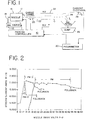
- Figure 1 is a block diagram of an ink jet printer system suitable for use with the present invention;
- Figure 2 is a plot of nozzle drive signal versus deflected stream current for three different nozzles, illustrating the detection of the print window;
- Figure 3 is a software flow diagram illustrating the manner in which the microprocessor associated with the ink jet printer may be programmed, according to the invention, to detect the print window;
- Figure 4 is a plot of nozzle drive voltage versus stream current illustrating additional capabilities of the invention to detect operating characteristics of different nozzle types;
- Figure 5 is an illustration of drop break off from an ink stream, useful in understanding the present invention;
- Figure 6 is a plot illustrating the change in print window as a function of the magnitude of the drop charging voltage; and
- Figure 7 is a plan view of an alternate embodiment using a two-part segmented catcher instead of a separate current electrode.
-
- Referring to Figure 1, there is illustrated an ink jet printing apparatus suitable for use with the present invention. The printer includes a
print controller 10 of the type typically used in this industry. Thecontroller 10 includes a micro-processor or similar device programmed to operate the ink jet printer according to the parameters set by the operator. The controller regulates the supply of ink from asource 12 via anink supply conduit 14 to anozzle 16. A stimulation voltage waveform or drive voltage waveform is applied to the nozzle, usually through apiezoelectric device 17, in a manner well known in this art at a frequency selected to cause break up into droplets of the stream ofink 18 ejected from the nozzle. The drop break off point is a function of the ink pressure, the nozzle diameter and the magnitude of the applied nozzle drive voltage, among other factors. In order to charge the droplets as they break off from thestream 18, it is necessary that the break off point occurs within acharge tunnel 20. Charged drops are thereafter deflected by a pair ofdeflection electrodes 22 in the course of travel toward a substrate to be marked (not shown). That is, drops which carry a charge are deflected onto the substrate while uncharged drops pass undeflected through the electrodes. Preferably, the uncharged drops are directed toward acatcher 24 which returns the ink to asump 26 and/or to theink source 12 for reuse. Not shown, but typically included in a standard printer of this type, are fresh ink reservoirs, solvent reservoirs and valves controlled by thecontroller 10 for maintaining the quality of the ink relatively constant during the course of the printing operation. - From the foregoing, it will be apparent that when drops emerge from the
charge tunnel 20, those which have been given an electric charge within the tunnel are deflected while uncharged drops pass to thecatcher 24. For purposes of the present invention, it is necessary to create a test pattern of drops wherein each charged drop is separated by one or more uncharged drops commonly known in this art as guard drops. At least one guard drop is required between each charged drop for purposes of the present invention, although several guard drops are typically used. - The automatic nozzle setting function of the invention is accomplished by use of a
sensing electrode 28 disposed at the point where the deflected drops would normally reach the substrate to be marked. Obviously, the sensing electrode is in place only during the period of time when the print window is being determined and is thereafter removed so that normal printing can occur. Thesensing electrode 28 is connected to a current measuring circuit or device, such as anammeter 30, or preferably a picoammeter. The current detected by the current measuring device is provided to theprint controller 10 which uses this information to determine the print window in the manner described hereafter. - Before proceeding further, it will be useful to understand more precisely what is meant by the term "print window". For that purpose, reference is made to Figure 2 which illustrates plots of stream current versus nozzle drive voltage as detected by the
sensing electrode 28 for three different nozzles. In the nozzle represented by the solid circles, a maximum stream current of approximately seven nanoamps is maintained over nozzle drive voltages from twenty through forty-three. Thus, the print window (PW), or useful printing range for this particular nozzle, is extremely wide and good printing results can be obtained anywhere therein simply by setting the nozzle drive voltage to a value within this window, for example, thirty volts. - In contrast, the nozzle represented by the open circles, has a print window beginning at approximately thirteen volts and terminating at approximately eighteen volts. Thus, the print window for this nozzle is much more limited. It is required, when using such a nozzle, to carefully and precisely set the nozzle drive voltage to a value within the rather narrow print window.
- Figure 2 shows a third nozzle, which may be considered, for present purposes, to be defective. It is illustrated by the waveform carrying the triangular markers. It can be seen that this nozzle has a peak stream current at approximately thirteen volts, but that it rises to and falls from that value so rapidly that there is no effective print window.
- From Figure 2 the importance of accurately determining the print window for a particular nozzle, type of ink, and font size can be perceived. The ability to accurately and directly determine a print window for any given printer setup ensures that good printing can be maintained for significant periods of time. Failure to accurately set the nozzle drive within the print window can result in variable printing results or poor printing results if the drive setting is set at the edge of a print window or is outside the print window.
- Heretofore it has been possible only to estimate the print window for a particular printing system. Such methods locate the foldback voltage for the drop stream (as an approximate upper bound on the print window) and merely estimated where the print window ought to be by using some fraction of the foldback voltage. While usually satisfactory, this method is not as precise and does lead occasionally to less than satisfactory results, particularly when installing a new nozzle or changing inks or font sizes.
- According to the present invention, the current of the test drops which have been charged is measured while incrementing the nozzle drive voltage from a minimum value or decrementing the nozzle drive voltage from a maximum value. The print window is accurately determined by recording the stream current versus nozzle drive voltage to determine the voltage range where stream current remains near its maximum value. This is the print window or good printing region for any particular nozzle, ink, and font in most ink jet printers. The reason for this can be understood with reference to Figure 5. Figure 5 illustrates the manner in which the stream of
ink 18 breaks up intodrops 42 andsatellites 44. The breakup must occur within thecharge tunnel 20 in order for the drops to be properly charged. Assuming that condition, the next issue is whether thesatellites 44 are infinite satellites, that is, they remain interleaved between thedrops 42 or whether they merge forwardly or rearwardly with thedrops 42. The motion of thesatellites 44 is a function of the nozzle drive voltage, but is also charge dependent. For proper printing, it is usually desired to have the satellites merge forwardly to ensure that the total charge induced by thecharge tunnel 20 is on a particular drop. In that regard, it should be noted that the satellites are simply a small trailing portion of a drop which breaks off therefrom during or after the separation process within the charge tunnel and that in order for the full charge to be detected, each satellite must recombine with its "parent" drop. - In contrast, rearwardly merging satellites deplete the charge that was initially present on a drop and this is detected according to the present invention, as is the infinite satellite condition where the satellites do not recombine. As noted previously, according to the present invention, each charged drop is separated by at least one and preferably several guard drops which carry relatively no charge. Thus, if the satellites are forwardly merging the total charge induced by the charge tunnel will be present on a charged drop when it reaches the
sensing electrode 28 in Figure 1. In the event that the satellites do not forwardly merge because they are infinite or because they are rearwardly merging, the charged drops which are deflected to thesensing electrode 28 will have a lower charge than would otherwise be the case. By collecting drop current data according to the invention, the print window for a particular print set-up can be accurately determined. - The upper and lower bounds of the print window are a function of the nozzle drive voltage required to cause the satellites to forwardly merge, although the upper bound of the print window is also charge dependent. If a high charge is applied to the drops, electrostatic repulsion begins to overcome the forward momentum of the satellites, thus reducing the width of the print window. Increased charges are used for increased drop deflection to print large characters. The manner in which a print window changes for different charges applied to the drops can be seen in Figure 6, which illustrates that the print window for drops charged at 300 volts is markedly smaller than the print window for drops charged at 150 volts. It is for this reason, among others, that the present invention is a significant improvement over the prior art because it measures the actual print window using a particular charge level, ink type and nozzle, thereby precisely determining the good printing range. Prior methods, which only estimate the print window from a determination of the foldback voltage, do not compensate for these conditions resulting in the need for manual readjustments.
- Referring to Figures 1 and 3, the manner in which the print window is determined will now be described. Figure 3 is a software flow diagram illustrating the manner in which the
print controller 10, preferably a microprocessor based device, is programmed to obtain the necessary data. Atstep 50 the nozzle drive voltage applied tonozzle 16 is set to a predetermined value. The predetermined value will be a voltage greater than the foldback value if the data is to be taken by decrementing the nozzle drive voltage or it will be a very small value, at or above the infinite satellite voltage, if the data will be taken by incrementing the nozzle drive. It should be noted, as described in U.S. Patent No. 5,196,860, hereby incorporated by reference, that the infinite satellite condition and the foldback condition can be easily determined automatically or by the operator. - Once the nozzle drive has been set at an initial value, the controller causes a set of test drops to be generated in a specified pattern wherein a charge drop is separated by at least one and preferably several, uncharged guard drops. The
sensing electrode 28 is placed in a path to intercept the charged drops which are deflected by thehigh voltage electrode 22 and to route the resulting current to anammeter 30 for quantification. Thus, atstep 52, the deflected jet stream current is measured by theammeter 30. At 54 a check is made to determine if the subroutine should terminate because it has reached the end of the print window. If this is the first time through, the answer will be "no" and the software branches to 56 where it stores the data on the stream current and nozzle drive voltage magnitudes. The nozzle drive is then decremented at 58 from its high initial value (or incremented if the initial value is below the print window) and steps 52 and 54 are repeated to obtain several more data points. Preferably a sufficient number of data points should be taken in order to provide a clear measurement of the print window. - Eventually, the program detects the low end of the print window by virtue of the fact that the magnitude of the stream current has fallen markedly from its maximum value. In the event that the nozzle drive is being decremented for testing, this feature indicates that the nozzle is no longer being driven sufficiently to cause the satellites to forwardly merge. In the case where the nozzle drive is being incremented, this feature indicates that the upper bound has been reached. In either case, data sampling terminates and the program branches to 60 for calculation of the print window. This is done using standard data handling techniques whereby the data collected is converted into a set of data points on a stream current versus nozzle drive graph as shown in Figure 2. This information can be presented to the operator on a video display or printed out as a table of values. The data, once obtained, is used to set the nozzle drive as indicated at 62 either automatically by selecting a point within the mid-range of the print window or manually should the operator of the printing device prefer. The set-up routine then ends.
- Prior to initiating printing, the
sensing electrode 28 is removed from the path of the charged drops. Whenever the parameters of the printer change as, for example, a new nozzle is used, a different ink is employed or a different font size is selected, the set-up routine of Figure 3 may be initiated to ensure that the nozzle drive voltage selected is the appropriate value for the current printer setup. - It is also possible to deflect the charged test drops to the side of a segmented catcher. This eliminates the need for placing and removing a sensing electrode. Such an embodiment of the invention is shown in Figure 7, a top view. As with the embodiment of Figure 1, the
nozzle 16 creates a series of drops which are charged bycharge tunnel 20. A segmented catcher is provided having amain segment 50 and anauxiliary segment 52. Guard drops which are substantially uncharged pass to themain section 50 of the catcher. Theauxiliary section 52 is offset to the side of the main catcher. The charged test drops are deflected to theauxiliary catcher 52 by a separate, specialpurpose deflection electrode 54. This electrode is operational only during the period of time when the printing window is being determined. It is positioned, as shown in Figure 7, to deflect the test drops toward theauxiliary catcher 52. In this embodiment, thedeflection electrodes 22 used for normal printing, are not operational during the print window determination sequence. The necessary current value I2 is determined by incorporating a current sensing electrode into theauxiliary catcher segment 52. - Although the set-up shown in Figure 7 is a presently preferred embodiment, it is also possible to determine the current value I2 in the Figure 1 embodiment without a separate sensing electrode. It is possible to measure the total current It in the ink stream 14 (see Figure 1) and then subtract the current I1 detected at the catcher. I1 can be detected using an electrode incorporated into the catcher in a manner well known in this art. The value It can be measured at the
drop stream 18 in the vicinity of the charge tunnel or from the ink stream as it enters the nozzle. For this technique, the deflection voltage must be such that small satellites are not attracted to the high voltage deflection electrode. This indirect method of measuring I2 does not compromise the ability of the present invention to precisely determine the print window for a given printer set up, as opposed to the more limited capability of the prior art of simply estimating the print window based on determining the foldback value. - It is also possible to practice the present invention by detecting the charge on the test drops. In that case, the
electrode 28 would be replaced with a capacitive or other type charge detector located near the path of the deflected drop stream. Charged drops will induce an output proportional to the charge, the nature of the output depending on the type of detector. This permits determination of the charge magnitude which can be used, in the same way as described for the charge current, to determine the print window. - In addition to determining the print window, the routine and hardware of the present invention can be used for printer servicing to test the printer for nozzle orifice size compliance, drop spacing, charge electrode spacing and other operating parameters.
Claims (10)
- A method for accurately determining the print window for an ink jet printer, characterised in that the method comprises the steps of:a) generating a series of charged test drops, each of which is preceded and followed by uncharged guard drops;b) setting the nozzle drive voltage at an initial value above the expected print window;c) decrementing the nozzle drive voltage from said initial value in steps;d) determining the stream current corresponding to the charges on the test drops at each step; ande) determining the print window as equal to the range of nozzle drive voltages where said stream current is approximately equal to its maximum value.
- A method for accurately determining the print window for an ink jet printer, characterised in that the method comprises the steps of:a) generating a series of charged test drops, each of which is preceded and followed by uncharged guard drops;b) setting the nozzle drive voltage at an initial value below the expected print window;c) incrementing the nozzle drive voltage from said initial value in steps;d) determining the stream current corresponding to the charges on the test drops at each step; ande) determining the print window as equal to the range of nozzle drive voltage where said stream current is approximately equal to its maximum value.
- A method for determining the good printing range for a printer which employs a nozzle to project a stream of marking fluid under pressure toward a target, characterised in that the method comprises the steps of:a) applying time varying signals to the nozzle that perturbate the stream to form a series of regularly spaced drops;b) charging selected ones of the drops in a repetitive pattern;c) detecting the magnitude of the charge on said selected drops; andd) determining the range over which the charge magnitude remains substantially at a maximum.
- A method as claimed in any one of Claims 1 to 3 further including the step of:a) setting the nozzle drive voltage to a value within the print window for printing.
- A method as claimed in Claims 1,2 or 1 and 4, wherein step (d) includes the substeps of deflecting the test drops from the path of the guard drops and determining the charge on said test drops.
- An ink jet printer having an ink source, a nozzle assembly (16) for creating an ink stream which breaks into drops, a drop charging electrode (20), deflection electrodes (22), an ink catcher (24) for uncharged drops, characterised in that the ink jet printer further comprises:a) means for generating a series of test drops charged by said charge electrode (20), each of said test drops being preceded and followed by uncharged guard drops;b) means (28, 30) for determining the stream current carried by the charged, test drops; andc) controller means (10) for:i) applying a series of nozzle drive voltages to said nozzle starting at an initial value;ii) stepping the nozzle drive voltage from said initial value through an expected printing range (print window) and beyond; andiii) recording the stream current determined for each nozzle drive voltage step and determining the print window as equal to the range of nozzle drive voltages where the stream current is approximately equal to the maximum stream current.
- A printer as claimed in Claim 6, wherein said controller means (10) includes means for setting the nozzle drive voltage at a value within the print window for printing.
- A printer as claimed in Claim 6 or 7, wherein said means for determining the stream current includes an ammeter (30) disposed in the path of said current resulting from the charged test drops.
- A printer as claimed in any one of Claims 6 to 8, wherein said catcher (50, 52) is segmented to receive the test drops and guard drops separately and includes means for measuring the charge on said test drops;said printer further including an additional deflection electrode (54) positioned to deflect said charged test drops to said catcher measuring means.
- A printer as claimed in Claim 6, wherein said means for determining includes:a) means associated with said catcher for measuring the amount of stream current I1 transferred to said guard drops;b) means associated with the ink stream for measuring the total current, It, thereby to determine the stream current of said test drops as equal to It - I1.
Applications Claiming Priority (2)
| Application Number | Priority Date | Filing Date | Title |
|---|---|---|---|
| US442005 | 1995-05-16 | ||
| US08/442,005 US5867194A (en) | 1995-05-16 | 1995-05-16 | Method and apparatus for automatic setting of nozzle drive voltage in an ink jet printer |
Publications (3)
| Publication Number | Publication Date |
|---|---|
| EP0744292A2 EP0744292A2 (en) | 1996-11-27 |
| EP0744292A3 EP0744292A3 (en) | 1997-07-23 |
| EP0744292B1 true EP0744292B1 (en) | 2000-01-19 |
Family
ID=23755154
Family Applications (1)
| Application Number | Title | Priority Date | Filing Date |
|---|---|---|---|
| EP96303040A Expired - Lifetime EP0744292B1 (en) | 1995-05-16 | 1996-04-30 | Method and apparatus for automatic setting of nozzle drive voltage in an ink jet printer |
Country Status (6)
| Country | Link |
|---|---|
| US (1) | US5867194A (en) |
| EP (1) | EP0744292B1 (en) |
| JP (1) | JP3853420B2 (en) |
| CA (1) | CA2175770A1 (en) |
| DE (1) | DE69606222T2 (en) |
| ES (1) | ES2141442T3 (en) |
Families Citing this family (10)
| Publication number | Priority date | Publication date | Assignee | Title |
|---|---|---|---|---|
| GB9626708D0 (en) * | 1996-12-23 | 1997-02-12 | Domino Printing Sciences Plc | Continuous ink jet print head control |
| DE69716871T2 (en) * | 1997-03-03 | 2003-07-17 | Scitex Digital Printing, Inc. | Self-configuring inkjet printer |
| US6626513B2 (en) | 2001-07-18 | 2003-09-30 | Lexmark International, Inc. | Ink detection circuit and sensor for an ink jet printer |
| US6793327B2 (en) * | 2002-09-25 | 2004-09-21 | Eastman Kodak Company | Low catch voltage startup |
| KR100667761B1 (en) * | 2004-08-18 | 2007-01-11 | 삼성전자주식회사 | Method for deciding a driving signal of a print head by using an image forming apparatus |
| US7992956B2 (en) | 2006-06-07 | 2011-08-09 | Applied Materials, Inc. | Systems and methods for calibrating inkjet print head nozzles using light transmittance measured through deposited ink |
| FR2971451B1 (en) | 2011-02-11 | 2013-03-15 | Markem Imaje | STIMULATION RANGE DETECTION IN A CONTINUOUS INK JET PRINTER |
| CN107364237B (en) * | 2013-04-26 | 2019-09-10 | 科迪华公司 | For the method and apparatus to pad-ink the drop measurement and control of deposits fluid in precision tolerances |
| JP6657625B2 (en) * | 2014-09-05 | 2020-03-04 | ソニー株式会社 | Droplet sorting apparatus, drop sorting method and program |
| CN107933090B (en) * | 2017-12-20 | 2023-05-26 | 北京赛腾标识系统股份公司 | Device and method for setting nozzle drive and ink jet system |
Family Cites Families (3)
| Publication number | Priority date | Publication date | Assignee | Title |
|---|---|---|---|---|
| DE2611282C3 (en) * | 1975-03-17 | 1981-10-08 | Hitachi, Ltd., Tokyo | Device for correcting droplet deflection in an inkjet printer |
| US4878064A (en) * | 1988-10-31 | 1989-10-31 | Eastman Kodak Company | Continuous ink jet stimulation adjustment based on overdrive detection |
| US5196860A (en) * | 1989-03-31 | 1993-03-23 | Videojet Systems International, Inc. | Ink jet droplet frequency drive control system |
-
1995
- 1995-05-16 US US08/442,005 patent/US5867194A/en not_active Expired - Fee Related
-
1996
- 1996-04-30 ES ES96303040T patent/ES2141442T3/en not_active Expired - Lifetime
- 1996-04-30 EP EP96303040A patent/EP0744292B1/en not_active Expired - Lifetime
- 1996-04-30 DE DE69606222T patent/DE69606222T2/en not_active Expired - Fee Related
- 1996-05-03 CA CA002175770A patent/CA2175770A1/en not_active Abandoned
- 1996-05-15 JP JP12016696A patent/JP3853420B2/en not_active Expired - Fee Related
Also Published As
| Publication number | Publication date |
|---|---|
| DE69606222T2 (en) | 2000-09-07 |
| US5867194A (en) | 1999-02-02 |
| DE69606222D1 (en) | 2000-02-24 |
| CA2175770A1 (en) | 1996-11-17 |
| EP0744292A3 (en) | 1997-07-23 |
| EP0744292A2 (en) | 1996-11-27 |
| ES2141442T3 (en) | 2000-03-16 |
| JP3853420B2 (en) | 2006-12-06 |
| JPH08309969A (en) | 1996-11-26 |
Similar Documents
| Publication | Publication Date | Title |
|---|---|---|
| US4417256A (en) | Break-off uniformity maintenance | |
| EP0744292B1 (en) | Method and apparatus for automatic setting of nozzle drive voltage in an ink jet printer | |
| US4616234A (en) | Simultaneous phase detection and adjustment of multi-jet printer | |
| US4047183A (en) | Method and apparatus for controlling the formation and shape of droplets in an ink jet stream | |
| US4484199A (en) | Method and apparatus for detecting failure of an ink jet printing device | |
| EP0039772B1 (en) | Multinozzle ink jet printer and method of operating such a printer | |
| US5434609A (en) | Deflection system for deflecting charged particles | |
| US4573057A (en) | Continuous ink jet auxiliary droplet catcher and method | |
| EP0036930B1 (en) | Ink jet printers and method of controlling an ink jet printer | |
| EP0481797B1 (en) | Character height control for drop markers | |
| US4638325A (en) | Ink jet filament length and stimulation amplitude assessment system | |
| US5523778A (en) | Segmented charge tunnel for drop charging in a printhead | |
| JPS63500509A (en) | Induced amplitude adjustment method and apparatus in continuous ink jet printer | |
| EP0964784B1 (en) | Continuous inkjet printhead control | |
| US7393085B2 (en) | Method of operating a continuous ink jet printer apparatus | |
| US5517216A (en) | Ink jet printer employing time of flight control system for ink jet printers | |
| EP0036789A1 (en) | Liquid jet printing apparatus | |
| EP0964785B1 (en) | Continuous ink jet print head control | |
| US10647114B2 (en) | Continuous inkjet printers | |
| EP0968088B1 (en) | Continuous ink jet printing | |
| US6758547B2 (en) | Method and apparatus for machine specific overcurrent detection | |
| WO2023017684A1 (en) | Inkjet recording device and inkjet recording method | |
| WO1998028151A9 (en) | Continuous ink jet printing | |
| EP0964786A1 (en) | Continuous ink jet print head control | |
| EP1013424A2 (en) | Apparatus and method for controlling a charging voltage in ink jet printers |
Legal Events
| Date | Code | Title | Description |
|---|---|---|---|
| PUAI | Public reference made under article 153(3) epc to a published international application that has entered the european phase |
Free format text: ORIGINAL CODE: 0009012 |
|
| AK | Designated contracting states |
Kind code of ref document: A2 Designated state(s): DE ES FR GB IT NL |
|
| PUAL | Search report despatched |
Free format text: ORIGINAL CODE: 0009013 |
|
| AK | Designated contracting states |
Kind code of ref document: A3 Designated state(s): DE ES FR GB IT NL |
|
| 17P | Request for examination filed |
Effective date: 19980116 |
|
| GRAG | Despatch of communication of intention to grant |
Free format text: ORIGINAL CODE: EPIDOS AGRA |
|
| 17Q | First examination report despatched |
Effective date: 19990325 |
|
| GRAG | Despatch of communication of intention to grant |
Free format text: ORIGINAL CODE: EPIDOS AGRA |
|
| GRAH | Despatch of communication of intention to grant a patent |
Free format text: ORIGINAL CODE: EPIDOS IGRA |
|
| GRAH | Despatch of communication of intention to grant a patent |
Free format text: ORIGINAL CODE: EPIDOS IGRA |
|
| GRAA | (expected) grant |
Free format text: ORIGINAL CODE: 0009210 |
|
| AK | Designated contracting states |
Kind code of ref document: B1 Designated state(s): DE ES FR GB IT NL |
|
| ITF | It: translation for a ep patent filed | ||
| ET | Fr: translation filed | ||
| REF | Corresponds to: |
Ref document number: 69606222 Country of ref document: DE Date of ref document: 20000224 |
|
| REG | Reference to a national code |
Ref country code: ES Ref legal event code: FG2A Ref document number: 2141442 Country of ref document: ES Kind code of ref document: T3 |
|
| PLBE | No opposition filed within time limit |
Free format text: ORIGINAL CODE: 0009261 |
|
| STAA | Information on the status of an ep patent application or granted ep patent |
Free format text: STATUS: NO OPPOSITION FILED WITHIN TIME LIMIT |
|
| 26N | No opposition filed | ||
| PGFP | Annual fee paid to national office [announced via postgrant information from national office to epo] |
Ref country code: NL Payment date: 20010430 Year of fee payment: 6 |
|
| REG | Reference to a national code |
Ref country code: GB Ref legal event code: IF02 |
|
| PGFP | Annual fee paid to national office [announced via postgrant information from national office to epo] |
Ref country code: ES Payment date: 20020423 Year of fee payment: 7 |
|
| PG25 | Lapsed in a contracting state [announced via postgrant information from national office to epo] |
Ref country code: NL Free format text: LAPSE BECAUSE OF NON-PAYMENT OF DUE FEES Effective date: 20021101 |
|
| NLV4 | Nl: lapsed or anulled due to non-payment of the annual fee |
Effective date: 20021101 |
|
| PG25 | Lapsed in a contracting state [announced via postgrant information from national office to epo] |
Ref country code: ES Free format text: LAPSE BECAUSE OF NON-PAYMENT OF DUE FEES Effective date: 20030503 |
|
| REG | Reference to a national code |
Ref country code: ES Ref legal event code: FD2A Effective date: 20030503 |
|
| PG25 | Lapsed in a contracting state [announced via postgrant information from national office to epo] |
Ref country code: IT Free format text: LAPSE BECAUSE OF NON-PAYMENT OF DUE FEES Effective date: 20050430 |
|
| PGFP | Annual fee paid to national office [announced via postgrant information from national office to epo] |
Ref country code: DE Payment date: 20070426 Year of fee payment: 12 |
|
| PGFP | Annual fee paid to national office [announced via postgrant information from national office to epo] |
Ref country code: GB Payment date: 20070425 Year of fee payment: 12 |
|
| PGFP | Annual fee paid to national office [announced via postgrant information from national office to epo] |
Ref country code: FR Payment date: 20070411 Year of fee payment: 12 |
|
| GBPC | Gb: european patent ceased through non-payment of renewal fee |
Effective date: 20080430 |
|
| PG25 | Lapsed in a contracting state [announced via postgrant information from national office to epo] |
Ref country code: DE Free format text: LAPSE BECAUSE OF NON-PAYMENT OF DUE FEES Effective date: 20081101 |
|
| REG | Reference to a national code |
Ref country code: FR Ref legal event code: ST Effective date: 20081231 |
|
| PG25 | Lapsed in a contracting state [announced via postgrant information from national office to epo] |
Ref country code: FR Free format text: LAPSE BECAUSE OF NON-PAYMENT OF DUE FEES Effective date: 20080430 |
|
| PG25 | Lapsed in a contracting state [announced via postgrant information from national office to epo] |
Ref country code: GB Free format text: LAPSE BECAUSE OF NON-PAYMENT OF DUE FEES Effective date: 20080430 |