EP0557753B1 - Protection device of an apparatus - Google Patents
Protection device of an apparatus Download PDFInfo
- Publication number
- EP0557753B1 EP0557753B1 EP93101707A EP93101707A EP0557753B1 EP 0557753 B1 EP0557753 B1 EP 0557753B1 EP 93101707 A EP93101707 A EP 93101707A EP 93101707 A EP93101707 A EP 93101707A EP 0557753 B1 EP0557753 B1 EP 0557753B1
- Authority
- EP
- European Patent Office
- Prior art keywords
- heating element
- switches
- thermostatic
- switch
- thermostatic switches
- Prior art date
- Legal status (The legal status is an assumption and is not a legal conclusion. Google has not performed a legal analysis and makes no representation as to the accuracy of the status listed.)
- Expired - Lifetime
Links
Images

Classifications
-
- H—ELECTRICITY
- H01—ELECTRIC ELEMENTS
- H01H—ELECTRIC SWITCHES; RELAYS; SELECTORS; EMERGENCY PROTECTIVE DEVICES
- H01H1/00—Contacts
- H01H1/50—Means for increasing contact pressure, preventing vibration of contacts, holding contacts together after engagement, or biasing contacts to the open position
- H01H1/504—Means for increasing contact pressure, preventing vibration of contacts, holding contacts together after engagement, or biasing contacts to the open position by thermal means
Definitions
- the present invention relates to a device for protecting a device, e.g. a discharge lamp, with an opening thermal switch connected in series with the device and its power supply to interrupt the power supply in the event of overtemperature, and a heating element which is connected to the power supply instead of the device in the event of overtemperature.
- a device e.g. a discharge lamp
- an opening thermal switch connected in series with the device and its power supply to interrupt the power supply in the event of overtemperature
- a heating element which is connected to the power supply instead of the device in the event of overtemperature.
- Such a device is known from FR-A-1 401 964.
- the thermal switch is a changeover switch that either connects the device to be protected or the heating resistor to the power supply.
- the device and the heating resistor are connected at one end and connected to the power supply, while the other two connections of the device and the heating element can optionally be connected to the other connection of the power supply via the thermal switch.
- the device to be protected is connected to the power supply below the response temperature of the thermal switch. If the temperature of the device now rises in an impermissible manner, the thermal switch switches over, i.e. disconnects the device from the power supply and instead connects the heating resistor to the power supply. The heating resistor now flowed through by the current develops a heat that is sufficient to keep the thermal switch open.
- the known thermal switch is a special component in which the heating resistor is integrated into the housing, but must nevertheless be connected separately.
- a thermal switch that opens when the temperature rises is provided in parallel with a heating element, both of which are connected in series with the load to be protected.
- the closed thermal switch has a low resistance, so that the current flows essentially through it, while practically no current flows through the heating element connected in parallel, so that it does not heat either. If the load to be protected reaches an excess temperature due to a fault, the temperature switch is opened so that no current can flow to the load through it.
- the very low residual current is not sufficient in the event of a fault to keep the thermal switch open, so that undesirable clocking occurs here.
- the thermal switch designed as a changeover switch is also a special component with all the associated disadvantages.
- this object is achieved according to the invention in that a further, closing thermal switch is provided, which is arranged in series with the heating element, the series circuit comprising the heating element and the thermal switch being arranged parallel to the series circuit comprising the device and the thermal switch.
- a pure closer in addition to the pure opener, a pure closer is also provided, both of which are constructed in the usual way.
- the thermal switch lying in series with the load is opened and, at the same time, the closing thermal switch lying parallel to the load and the opening thermal switch is closed, so that the heating connected in series with the supply voltage sets. Now there is a current flow through the heater, which heats up the heater so that it can open the opening thermal switch and keep the closing thermal switch closed.
- the heating element is self-stabilizing, the heating element in particular being a PTC thermistor.
- the switches are bimetallic switches.
- the heating element is in direct thermal contact with the switches, the switches and the heating element in particular being arranged in a common envelope.
- the bimetallic switches are arranged in an electrically conductive housing which forms one of their contacts, in particular the heating element between the two metallic conductive housings of the switches being arranged in contact with them and only the circuit breaker but not the closing switch is provided with an electrical connection on its housing.
- a preferred specific embodiment provides that the two switches are arranged with their bottoms facing one another with the heating element being interposed, whereby an additional mechanical preservation can be achieved in that the entire unit consisting of the two switches and the heating element is arranged, for example, in a shrink tube .
- switches are arranged next to one another, the heating element being arranged below their bottoms and forming an electrical and thermal bridge, and that the two switches are next to each other are arranged and the heating element is arranged between them, in the latter case the heating element being arranged between two flat legs of electrically conductive transmission angles, the further angled leg of which touches the bottom of the switch at the bottom.
- a further embodiment provides that the switches are covered on their top by an insulating layer, which only has an opening in the central areas of the switches Contacting of electrical connections at the further contact of the switches are left free.
- the device according to the invention is used to protect against overtemperature in a load in which only a small residual current flows in the event of a fault that this does not result in the heating resistor being connected in parallel with this, but together with these in series with the heating resistor, for the usual self-holding of the thermal circuit breaker is sufficient.
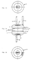
- a heater 3 and a thermal switch 4 acting as a make contact are connected or arranged in parallel with the thermal protective switch designed in the usual manner as an opener or thermal protective switch 2 and the load, as shown in FIG. 1 .
- Thermal protection switch 2 acting as a make contact thermal switch 4 are preferably formed as a unit that is spatially arranged close to the load 1 becomes.
- the heater 3 is a self-stabilizing resistor, such as a PTC thermistor, in particular in the form of a barium titanate PTC element.
- the thermal protection switch 2 and the closing switch 4 have the same switchover temperatures. If the switching temperature is exceeded due to an accident on the load 1, heat build-up or the like, the thermal protection switch 2 opens on the one hand, and the closing switch 4 closes on the other hand. By opening the thermal protection switch 2, the load 1 is removed from the mains and therefore protected. By closing the closing switch 4, the heater 3 is applied to the network and thus heats. A sufficient temperature is achieved by heating the heater 3, even if, after the load 1 has been switched off, this no longer generates an increased temperature in order to keep the thermal protection switch 2 open continuously and to cycle and thus switch the load 1 on and off again prevent.
- the thermal switches 2,4 are preferably designed as bimetallic switches in a manner known per se.
- FIGS. 2a to 2c A first specific embodiment of the device according to the invention is shown in FIGS. 2a to 2c.
- the thermal protection switch 2 and the closing switch 4 are bimetallic switches with a metallic housing 6 and 7, which are formed in the usual way and which form the one contact connection of the switches 2 and 4, respectively.
- the housings 6, 7 are flat pastille-like housings with a flat circular bottom.
- the switches 2, 4 are directed towards one another with their bases 8, 9 and that is between the bases 8, 9 Heating element 3 arranged. As I said, this consists of a PTC lozenge.
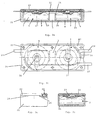
- the entire unit comprising switches 2, 4 and heating 3 are encased by a covering, such as a shrink tube, which holds the parts together and the switches 2, 4 from both sides against the heating 3 presses.
- the thermal protection switch 2 is provided on the one hand on its contact 13, which is insulated with respect to its housing 6 (on the end face opposite its base 8), with a connecting lead 14, and on the other hand with a connecting lead 16 on its housing, while the closing switch 4 is only insulated on its housing 7
- Contact 17 is provided with a lead 18.
- the connecting strands can be attached in the usual way, such as soldered or welded.
- the stranded wire 14 is connected to one side of the load 1, the stranded wire 16 to the one end of the network and the stranded wire 18 to the other side of the load and the other side of the network.
- the circuit of FIG. 1 is implemented in this way.
- the unit of FIGS. 2a to 2c is spatially closely arranged under the load, for example integrated in a discharge lamp luminaire.
- FIGS 3a to 3d show a further embodiment of the device according to the invention.
- the switches 2, 4 are arranged side by side in a flat insulating housing 21, which is closed by a cover 22, for example by means of rivets 23.
- the heating element 3 is arranged between the two switches 2, 4.
- the switches 2, 4 are seated on a lower leg 26, 27 of electrically conductive angle parts 28, 29, the side legs 31, 32 of which are parallel to each other next to the mutually facing sides of the switches 2, 4 extend and between which the heating element 3 is arranged.
- a pressing pressure is achieved in that the switches 2, 4 are held on their sides opposite the legs 31, 32 by formations 33, 34 of the housing 21 and are pressed against one another, so that the legs 31, 32 are pressed firmly against the heating element. This results in the desired good electrical and thermal contact.
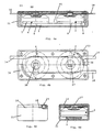
- connection contacts 14, 16, 18 are each designated with the same reference numerals as the corresponding connections in the configuration of FIGS. 2a to 2c. In the embodiment of FIGS. 3a to 3d, they are formed by flat tabs which, on the one hand, rest on connection 14, 18 on the upper contact of switches 2, 4, which is insulated from the respective housing 6, 7, and are pressed against them by cover 22, whereby tabs are led out of the side of the housing.
- the connection 16 has an arcuate contact part 36, which bears laterally within the form 33 on the side wall of the temperature protection switch 2.
- the contacts 14, 18 are provided with a resilient tab 37, 38.
- FIGS. 4a to 4d The configuration of FIGS. 4a to 4d is similar to that of FIGS. 3a to 3d.
- the same elements are drawn with the same reference numerals; with regard to the same elements, reference is made to the explanation of FIGS. 3a to 3d.
- an elongated heating element in the form of a PTC barium titanate strip or the like is arranged below the two switches 2, 4, which are arranged next to one another, as in FIGS. 3 a to 3 d, so that its top 41 on the bases 8, 9 the housing 6,7 the switch 2,4 is present.
- the contact pressure is brought about by the cover 22 attached. This creates a direct good heat and electrical contact between the switches 2,4 and the heating element 3.
Abstract
Description
Die vorliegende Erfindung betrifft eine Vorrichtung zum Schützen eines Gerätes, z.B. einer Entladungslampe, mit einem in Reihe mit dem Gerät und seiner Stromversorgung geschalteten öffnenden Thermoschalter zum Unterbrechen der Stromversorgung bei Übertemperatur, und einem Heizelement, das bei Übertemperatur statt des Gerätes an die Stromversorgung angeschlossen ist.The present invention relates to a device for protecting a device, e.g. a discharge lamp, with an opening thermal switch connected in series with the device and its power supply to interrupt the power supply in the event of overtemperature, and a heating element which is connected to the power supply instead of the device in the event of overtemperature.
Eine derartige Vorrichtung ist aus der FR-A-1 401 964 bekannt.Such a device is known from FR-A-1 401 964.
Bei der bekannten Vorrichtung ist der Thermoschalter ein Wechselschalter, der entweder das zu schützende Gerät oder aber den Heizwiderstand mit der Stromversorgung verbindet. Zu diesem Zweck sind Gerät und Heizwiderstand einen Endes zusammengeschaltet und mit der Stromversorgung verbunden, während die beiden anderen Anschlüsse von Gerät und Heizelement über den Thermoschalter wahlweise mit dem anderen Anschluß der Stromversorgung verbindbar sind.In the known device, the thermal switch is a changeover switch that either connects the device to be protected or the heating resistor to the power supply. For this purpose, the device and the heating resistor are connected at one end and connected to the power supply, while the other two connections of the device and the heating element can optionally be connected to the other connection of the power supply via the thermal switch.
Unterhalb der Ansprechtemperatur des Thermoschalters ist das zu schützende Gerät mit der Stromversorgung verbunden. Erhöht sich jetzt die Temperatur des Gerätes in unzulässiger Weise, so schaltet der Thermoschalter um, trennt also das Gerät von der Stromversorgung und verbindet statt dessen den Heizwiderstand mit der Stromversorgung. Der jetzt vom Strom durchflossene Heizwiderstand entwickelt eine Wärme, die ausreicht, den Thermoschalter offenzuhalten.The device to be protected is connected to the power supply below the response temperature of the thermal switch. If the temperature of the device now rises in an impermissible manner, the thermal switch switches over, i.e. disconnects the device from the power supply and instead connects the heating resistor to the power supply. The heating resistor now flowed through by the current develops a heat that is sufficient to keep the thermal switch open.
Der bekannte Thermoschalter ist ein Spezialbauteil, bei dem der Heizwiderstand zwar in das Gehäuse integriert ist, aber dennoch gesondert verschaltet werden muß.The known thermal switch is a special component in which the heating resistor is integrated into the housing, but must nevertheless be connected separately.
Bei vergleichbaren Vorrichtungen ist ein sich bei Übertemperatur öffnender Thermoschalter in Parallelanordnung zu einem Heizelement vorgesehen, wobei beide in Reihe mit der zu schützenden Last geschaltet sind. Der geschlossene Thermoschalter hat einen geringen Widerstand, so daß der Stromfluß im wesentlichen über diesen erfolgt, während über das parallel geschaltete Heizelement praktisch kein Stromfluß erfolgt, so daß dieses auch nicht heizt. Wenn aufgrund einer Störung die zu schützende Last eine Übertemperatur erreicht, wird der Temperaturschalter geöffnet, so daß über ihn kein Strom mehr zur Last fließen kann. Ein durch den Widerstand von Last- und Heizelement bestimmter geringer Strom, der aber dennoch zum Aufheizen des Heizelementes ausreicht, fließt jetzt über das Heizelement und erwärmt dieses, so daß der öffnende Thermoschalter durch das Heizelement geöffnet gehalten wird.In comparable devices, a thermal switch that opens when the temperature rises is provided in parallel with a heating element, both of which are connected in series with the load to be protected. The closed thermal switch has a low resistance, so that the current flows essentially through it, while practically no current flows through the heating element connected in parallel, so that it does not heat either. If the load to be protected reaches an excess temperature due to a fault, the temperature switch is opened so that no current can flow to the load through it. A low current determined by the resistance of the load and heating element, but which is nevertheless sufficient to heat the heating element, now flows over the heating element and heats it, so that the opening thermal switch is kept open by the heating element.
Bei gewissen Geräten, wie insbesondere Entladungslampen, reicht im Störfalle der sehr geringe Reststrom nicht aus, um den Thermoschalter offenzuhalten, so daß es hier zu einem unerwünschten Takten kommt.With certain devices, such as discharge lamps in particular, the very low residual current is not sufficient in the event of a fault to keep the thermal switch open, so that undesirable clocking occurs here.
Bei der aus der eingangs erwähnten FR-A-1 401 964 bekannten Vorrichtung wird dieses Takten auch bei solchen Geräten, bei denen im Störfall lediglich ein geringer Reststrom fließt, dadurch vermieden, daß das Gerät völlig von der Stromversorgung weggeschaltet wird und der Heizstrom lediglich durch den Widerstand des Heizelementes bestimmt wird.In the device known from the above-mentioned FR-A-1 401 964, this clocking is avoided even in the case of devices in which only a small residual current flows in the event of a malfunction, in that the device is completely disconnected from the power supply and the heating current only by the resistance of the heating element is determined.
Wegen des gesondert zu verdrahtenden Heizelementes ist der Montageaufwand bei der bekannten Vorrichtung jedoch relativ hoch. Der als Umschalter ausgebildete Thermoschalter ist darüber hinaus ein Spezialbauteil mit allen damit verbundenen Nachteilen.However, because of the heating element to be wired separately, the assembly effort in the known device is relatively high. The thermal switch designed as a changeover switch is also a special component with all the associated disadvantages.
Vor diesem Hintergrund ist es Aufgabe der vorliegenden Erfindung, die eingangs genannte Vorrichtung derart weiterzubilden, daß sie einfach aufgebaut werden kann und einfach zu verkabeln ist.Against this background, it is an object of the present invention to develop the device mentioned at the outset in such a way that it can be constructed simply and is easy to wire.
Bei der eingangs genannten Vorrichtung wird diese Aufgabe erfindungsgemäß dadurch gelöst, daß ein weiterer, schließender Thermoschalter vorgesehen ist, der in Reihe mit dem Heizelement angeordnet ist, wobei die Reihenschaltung aus Heizelement und Thermoschalter parallel zu der Reihenschaltung aus Gerät und Thermoschalter angeordnet ist.In the device mentioned in the introduction, this object is achieved according to the invention in that a further, closing thermal switch is provided, which is arranged in series with the heating element, the series circuit comprising the heating element and the thermal switch being arranged parallel to the series circuit comprising the device and the thermal switch.
Erfindungsgemäß wird also neben dem reinen Öffner noch ein reiner Schließer vorgesehen, die beide in üblicher Weise ausgebildet sind.According to the invention, in addition to the pure opener, a pure closer is also provided, both of which are constructed in the usual way.
Wenn bei einer Störung der Last eine Übertemperatur auftritt, wird dadurch der in Reihe mit der Last liegende Thermoschalter geöffnet und gleichzeitig der parallel zu der Last und dem öffnenden Thermoschalter liegende schließende Thermoschalter geschlossen, so daß dieser die mit ihm in Reihe geschaltete Heizung an die Versorgungsspannung legt. Nun findet ein Stromfluß durch die Heizung statt, der die Heizung aufheizt, so daß diese den öffnenden Thermoschalter geöffnet und den schließenden Thermoschalter geschlossen halten kann.If an overtemperature occurs in the event of a fault in the load, the thermal switch lying in series with the load is opened and, at the same time, the closing thermal switch lying parallel to the load and the opening thermal switch is closed, so that the heating connected in series with the supply voltage sets. Now there is a current flow through the heater, which heats up the heater so that it can open the opening thermal switch and keep the closing thermal switch closed.
Hierdurch wird sicher ein Takten des Öffners und damit eine zusätzliche Belastung der Last vermieden, bis die Spannung manuell geschaltet wird.This reliably avoids clocking the NC contact and thus an additional load on the load until the voltage is switched manually.
Gemäß bevorzugter Ausgestaltung ist vorgesehen, daß das Heizelement selbststabilisierend ist, wobei insbesondere das Heizelement ein Kaltleiter ist. Eine Weiterbildung sieht vor, daß die Schalter Bimetallschalter sind. Um eine kompakte Bauweise zu erreichen, sehen weitere Ausgestaltungen vor, daß das Heizelement in unmittelbarem Wärmekontakt zu den Schaltern steht, wobei insbesondere die Schalter und das Heizelement in einer gemeinsamen Umhüllung angeordnet sind.According to a preferred embodiment, it is provided that the heating element is self-stabilizing, the heating element in particular being a PTC thermistor. A further development provides that the switches are bimetallic switches. In order to achieve a compact design, further refinements provide that the heating element is in direct thermal contact with the switches, the switches and the heating element in particular being arranged in a common envelope.
In weiterer konkreter Ausbildung kann vorgesehen sein, daß die Bimetallschalter in einem elektrisch leitenden Gehäuse angeordnet sind, das einen ihrer Kontakte bildet, wobei insbesondere das Heizelement zwischen den beiden metallisch leitenden Gehäusen der Schalter diese berührend angeordnet ist und lediglich der Schutzschalter, nicht aber der Schließschalter an seinem Gehäuse mit einem elektrischen Anschluß versehen ist.In a further specific embodiment it can be provided that the bimetallic switches are arranged in an electrically conductive housing which forms one of their contacts, in particular the heating element between the two metallic conductive housings of the switches being arranged in contact with them and only the circuit breaker but not the closing switch is provided with an electrical connection on its housing.
Eine bevorzugte konkrete Ausgestaltung sieht vor, daß die beiden Schalter mit ihren Böden unter Zwischenlage des Heizelements gegeneinander gerichtet angeordnet sind, wobei ein zusätzlicher mechanischer Erhalt dadurch erreicht werden kann, daß die gesamte Einheit aus den beiden Schaltern und dem Heizelement beispielsweise in einem Schrumpfschlauch angeordnet ist.A preferred specific embodiment provides that the two switches are arranged with their bottoms facing one another with the heating element being interposed, whereby an additional mechanical preservation can be achieved in that the entire unit consisting of the two switches and the heating element is arranged, for example, in a shrink tube .
Alternative Ausgestaltungen sehen vor, daß die Schalter nebeneinander angeordnet sind, wobei das Heizelement unterhalb ihrer Böden angeordnet ist und eine elektrische sowie Wärmebrücke bildet, und daß die beiden Schalter nebeneinander angeordnet sind und das Heizelement zwischen ihnen angeordnet ist, wobei im letzteren Falle das Heizelement zwischen zwei ebenen Schenkeln elektrisch leitender Übertragungswinkel angeordnet sind, deren weiterer winkliger Schenkel unten den Boden der Schalter berührt.Alternative configurations provide that the switches are arranged next to one another, the heating element being arranged below their bottoms and forming an electrical and thermal bridge, and that the two switches are next to each other are arranged and the heating element is arranged between them, in the latter case the heating element being arranged between two flat legs of electrically conductive transmission angles, the further angled leg of which touches the bottom of the switch at the bottom.
Zur elektrischen Isolierung und Vermeidung jeglichen Leckstroms zwischen den beiden Schaltern, die vorzugsweise in der genannten gemeinsamen Umhüllung angeordnet sind, sieht eine weitere Ausbildung vor, daß die Schalter auf ihrer Oberseite durch eine Isolierschicht überdeckt sind, die lediglich in Mittelbereichen der Schalter mit einer Öffnung zur Kontaktierung von elektrischen Anschlüssen am weiteren Kontakt der Schalter freigelassen sind.To electrically isolate and avoid any leakage current between the two switches, which are preferably arranged in the above-mentioned common casing, a further embodiment provides that the switches are covered on their top by an insulating layer, which only has an opening in the central areas of the switches Contacting of electrical connections at the further contact of the switches are left free.
Weitere Vorteile und Merkmale der Erfindung ergeben sich aus den Ansprüchen und aus der nachfolgenden Beschreibung, in der Ausführungsbeispiele unter Bezugnahme auf die Zeichnung im einzelnen erläutert sind. Dabei zeigt:
Figur 1- eine schematische Darstellung der der erfindungsgemäßen Vorrichtung in ihren sämtlichen Ausgestaltungen zugrundeliegenden Schaltung;
- Figur 2a bis 2c
- eine erste Ausführungsform der erfindungsgemäßen Vorrichtung in Seitenansicht sowie Draufsicht von oben und von unten;
- Figuren 3a bis 3d
- eine zweite Ausführungsform der erfindungsgemäßen Vorrichtung in einem vertikalen Längsschnitt (Figur 3a), einer Phantomdarstellung in Draufsicht (Figur 3b), einer Stirnseitenansicht (3c) und einem vertikalen Querschnitt (3d); und
- Figuren 4a bis 4d
- eine weitere erfindungsgemäße Ausgestaltung der Vorrichtung mit gleichen Darstellungsweisen bzw. Sichtweisen wie die der Figuren 3a bis 3d.
- Figure 1
- a schematic representation of the circuit according to the invention in all of its configurations;
- Figure 2a to 2c
- a first embodiment of the device according to the invention in side view and top view from above and below;
- Figures 3a to 3d
- a second embodiment of the device according to the invention in a vertical longitudinal section (Figure 3a), a phantom view in plan view (Figure 3b), an end view (3c) and a vertical cross section (3d); and
- Figures 4a to 4d
- a further embodiment of the device according to the invention with the same presentation or views as that of Figures 3a to 3d.
Die erfindungsgemäße Vorrichtung dient zum Schutz vor Übertemperatur bei einer Last, bei der im Störfall nur noch ein so geringer Reststrom fließt, daß dies für die übliche Selbsthaltung des Thermo-Schutzschalters mit parallel zu diesen, aber gemeinsam mit diesen in Reihe zur Last geschalteten Heizwiderstand nicht ausreicht.The device according to the invention is used to protect against overtemperature in a load in which only a small residual current flows in the event of a fault that this does not result in the heating resistor being connected in parallel with this, but together with these in series with the heating resistor, for the usual self-holding of the thermal circuit breaker is sufficient.
Erfindungsgemäß ist daher vorgesehen, daß parallel zu dem in üblicher Weise vorgesehenen als Öffner bzw. Thermoschutzschalter 2 ausgebildeten Thermoschutzschalter und der Last gemeinsam in Reihe eine Heizung 3 und ein als Schließer wirkender Thermoschalter 4 geschaltet bzw. angeordnet sind, wie dies in Figur 1 dargestellt ist.According to the invention, it is therefore provided that a
Thermoschutzschalter 2, Heizung 3, als Schließer wirkender Thermoschalter 4 sind dabei vorzugsweise als eine Einheit ausgebildet, die räumlich nahe der Last 1 angeordnet wird. Die Heizung 3 ist in bevorzugter Ausgestaltung ein selbststabilisierender Widerstand, wie ein Kaltleiter, insbesondere in Form eines Bariumtitanat-PTC-Elements.
Der Thermoschutzschalter 2 und der Schließschalter 4 haben gleiche Umschalttemperaturen. Wenn die Schalttemperatur aufgrund eines Störfalls an der Last 1, eines Wärmestaus oder dergleichen überschritten wird, so öffnet einerseits der Thermoschutzschalter 2, andererseits schließt der Schließschalter 4. Durch das Öffnen des Thermoschutzschalters 2 wird die Last 1 vom Netz weggenommen und daher geschützt. Durch das Schließen des Schließschalters 4 wird die Heizung 3 an das Netz angelegt und heizt damit. Durch das Heizen der Heizung 3 wird eine ausreichende Temperatur erzielt, auch wenn nach dem Abschalten der Last 1 diese keine erhöhte Temperatur mehr erzeugt, um derart den Thermoschutzschalter 2 dauernd offenzuhalten und ein Takten und damit ein wieder Ein- und wieder Ausschalten der Last 1 zu verhindern.The
Die Thermoschalter 2,4 sind vorzugsweise als Bimetallschalter in an sich bekannter Weise ausgebildet.The
Eine erste konkrete Ausführungsform der erfindungsgemäßen Vorrichtung ist in den Figuren 2a bis 2c dargestellt.A first specific embodiment of the device according to the invention is shown in FIGS. 2a to 2c.
Der Thermoschutzschalter 2 und der Schließschalter 4 sind in üblicher Weise ausgebildete Bimetallschalter mit einem metallischen Gehäuse 6 bzw. 7, das jeweils den einen Kontaktanschluß des Schalters 2 bzw. 4 bildet. Die Gehäuse 6,7 sind flache pastillenartige Gehäuse mit einem flachen Kreisförmigen Boden. Bei der Ausgestaltung der Figuren 2a bis 2b sind die Schalter 2,4 mit ihren Böden 8,9 gegeneinander gerichtet und zwischen den Böden 8,9 ist das Heizelement 3 angeordnet. Dieses besteht, wie gesagt, aus einer PTC-Pastille. Es kann, soweit es in üblicher Weise metallisierte Oberflächen auf seiner Stirnseite 11,12 aufweist, mit den Böden der Schalter 2,4 verlötet sein, um derart nicht nur eine gute elektrische und eine gute Wärmeverbindung zu diesen zu bilden, sondern eine mechanische Verbindung, wodurch die gesamte Einheit als solche zusammengehalten wird. Es könnte weiterhin vorgesehen sein, daß zur alternativen oder zusätzlichen mechanischen Sicherung die gesamte Einheit aus Schaltern 2,4 und Heizung 3 durch eine Umhüllung, wie ein Schrumpfschlauch ummantelt sind, der die Teile zusammenhält und die Schalter 2, 4 von beiden Seiten gegen die Heizung 3 drückt.The
Der Thermoschutzschalter 2 ist einerseits an seinem gegenüber seinem Gehäuse 6 isolierten Kontakt 13 (auf der seinem Boden 8 gegenüberliegenden Stirnseite) mit einer Anschlußlitze 14, andererseits an seinem Gehäuse mit einer Anschlußlitze 16 versehen, während der Schließschalter 4 lediglich an seinem gegenüber dem Gehäuse 7 isolierten Kontakt 17 mit einer Anschlußlitze 18 versehen ist. Die Anschlußlitzen können in üblicher Weise befestigt, wie festgelötet oder festgeschweißt sein.The
Die Anschlußlitze 14 wird mit der einen Seite der Last 1, die Anschlußlitze 16 mit dem einen Anschluß des Netzes und die Anschlußlitze 18 mit der anderen Seite der Last und der anderen Seite des Netzes verbunden. Derart wird die Schaltung der Figur 1 realisiert. Die Einheit der Figuren 2a bis 2c wird räumlich eng bei der Last angeordnet, beispielsweise in einer Entladungslampenleuchte mitintegriert.The stranded
Die Figuren 3a bis 3d zeigen eine weitere Ausgestaltung der erfindungsgemäßen Vorrichtung. Hier sind die Schalter 2,4 gemeinsam nebeneinander in einem flachen isolierenden Gehäuse 21 angeordnet, welches durch einen Deckel 22 beispielweise mittels Nieten 23 verschlossen ist.Figures 3a to 3d show a further embodiment of the device according to the invention. Here, the
Zwischen den beiden Schaltern 2,4 ist das Heizelement 3 angeordnet. Um einen guten Wärme- und elektrischen Kontakt zu schaffen sitzen die Schalter 2,4 auf einem Unterschenkel 26,27 von elektrisch leitenden Winkelteilen 28,29 auf, deren Seitenschenkel 31,32 jeweils neben den einander zugewandten Seiten der Schalter 2,4 sich pararallel zueinander erstrecken und zwischen denen das Heizelement 3 angeordnet ist. Ein Preßdruck wird dadurch erreicht, daß die Schalter 2,4 an ihren den Schenkeln 31, 32 entgegengesetzten Seiten durch Formausbildungen 33, 34 des Gehäuses 21 gehalten sind und gegeneinander gedrückt werden, so daß die Schenkel 31,32 fest gegen das Heizelement gedrückt werden. Hierdurch wird der gewünschte gute elektrische und Wärme-Kontakt bewirkt.The
Die Anschlußkontakte 14,16,18 sind jeweils mit den gleichen Bezugszeichen bezeichnet wie die entsprechenden Anschlüsse bei der Ausgestaltung der Figuren 2a bis 2c. Bei der Ausgestaltung der Figuren 3a bis 3d sind sie durch flache Laschen gebildet, die einerseits auf Anschluß 14, 18 an dem gegenüber dem jeweiligen Gehäuse 6,7 isolierten oberen Kontakt der Schalter 2,4 anliegen und gegen diese durch den Deckel 22 gedrückt werden, wobei Laschen seitlich aus dem Gehäuse heraus geführt sind. Der Anschluß 16 weist ein bogenförmiges Kontaktteil 36 auf, welches seitlich innerhalb der Formausbildung 33 an der Seitenwand des Temperaturschutzschalters 2 anliegt.The
Im Kontaktbereich sind die Kontakte 14, 18 mit einer federnd anliegenden Lasche 37, 38 versehen.In the contact area, the
Die Ausgestaltung der Figuren 4a bis 4d ist ähnlich der der Figuren 3a bis 3d. Gleiche Elemente sind mit gleichen Bezugszeichen gezeichnet; hinsichtlich gleicher Elemente wird auf die Erläuterung der Figuren 3a bis 3d verwiesen. Bei dieser Ausgestaltung ist ein langgestrekktes Heizelement in Form eines PTC-Bariumtitanat-Streifens oder dergleichen unterhalb der beiden - ebenso wie bei den Figuren 3a bis 3d - nebeneinander angeordneten Schalter 2,4 angeordnet, so daß es mit seiner Oberseite 41 an den Böden 8,9 der Gehäuse 6,7 der Schalter 2,4 anliegt. Der Anpreßdruck wird ebenso wie bei der Ausgestaltung der Figuren 3a bis 3d durch den aufgesetzten Deckel 22 bewirkt. Hierdurch wird ein direkter guter Wärme- und elektrischer Kontakt zwischen den Schaltern 2,4 und dem Heizelement 3 erzeugt.The configuration of FIGS. 4a to 4d is similar to that of FIGS. 3a to 3d. The same elements are drawn with the same reference numerals; with regard to the same elements, reference is made to the explanation of FIGS. 3a to 3d. In this embodiment, an elongated heating element in the form of a PTC barium titanate strip or the like is arranged below the two
Claims (13)
- Device for protecting an appliance (1), for example a discharge lamp, havinga normally-closed thermostatic switch (2) connected in series with the appliance (1) and its power supply, to interrupt the power supply in the event of overheating, anda heating element (3) that in the event of overheating is connected to the power supply instead of the appliance (1),characterised in that a further normally-open thermostatic switch (4) is provided, which is arranged in series with the heating element (3), the series circuit comprising heating element (3) and thermostatic switch (4) being arranged in parallel with the series circuit comprising appliance (1) and thermostatic switch (2).
- Device according to Claim 1, characterised in that the heating element (3) is self-stabilizing.
- Device according to Claim 1 or 2, characterised in that the heating element (3) is a PTC thermistor.
- Device according to one of Claims 1 to 3, characterised in that the thermostatic switches (2, 4) are bimetallic switches.
- Device according to one of Claims 1 to 4, characterised in that the heating element (3) is in direct thermal contact with the thermostatic switches (2, 4).
- Device according to Claim 4 or Claim 4 and Claim 5, characterised in that the bimetallic switches are arranged in an electrically conducting housing (6, 7), which forms one of their contacts.
- Device according to one of the preceding Claims, characterised in that the thermostatic switches (2, 4) and the heating element (3) are arranged in a common sheathing.
- Device according to Claim 6, characterised in that the heating element (3) is arranged between and makes contact with the two metallic conducting housings (6, 7) of the thermostatic switches (2, 4) and only the normally-closed thermostatic switch (2), but not the normally-open thermostatic switch (4), is provided with an electrical connection (16) on its housing.
- Device according to Claim 8, characterised in that the two thermostatic switches (2, 4) are arranged with their bases (8, 9) opposite each other with the heating element (3) interposed between them.
- Device according to Claim 8, characterised in that the thermostatic switches (2, 4) are arranged alongside each other, the heating element (3) being arranged beneath their bases (8, 9) and forming an electrical as well as a thermal shunt.
- Device according to Claim 8, characterised in that the two thermostatic switches (2, 4) are arranged alongside each other and the heating element (3) is arranged between them.
- Device according to Claim 11, characterised in that the heating element (3) is arranged between two flat limbs (31, 32) of electrically conducting brackets (28, 29), whose further angled limb (26, 27) makes contact with the bases (8, 9) of the thermostatic switches (2, 4).
- Device according to one of Claims 9 to 11, characterised in that the top sides of the thermostatic switches (2, 4) are covered by an insulating layer, and are left exposed only in the central regions of the thermostatic switches (2, 4), with an opening for making electrical connections to the further contact of the thermostatic switches (2, 4).
Applications Claiming Priority (2)
| Application Number | Priority Date | Filing Date | Title |
|---|---|---|---|
| DE4205699A DE4205699A1 (en) | 1992-02-25 | 1992-02-25 | Device for protecting a device |
| DE4205699 | 1992-02-25 |
Publications (3)
| Publication Number | Publication Date |
|---|---|
| EP0557753A2 EP0557753A2 (en) | 1993-09-01 |
| EP0557753A3 EP0557753A3 (en) | 1994-01-05 |
| EP0557753B1 true EP0557753B1 (en) | 1997-05-02 |
Family
ID=6452503
Family Applications (1)
| Application Number | Title | Priority Date | Filing Date |
|---|---|---|---|
| EP93101707A Expired - Lifetime EP0557753B1 (en) | 1992-02-25 | 1993-02-04 | Protection device of an apparatus |
Country Status (3)
| Country | Link |
|---|---|
| EP (1) | EP0557753B1 (en) |
| AT (1) | ATE152545T1 (en) |
| DE (2) | DE4205699A1 (en) |
Families Citing this family (4)
| Publication number | Priority date | Publication date | Assignee | Title |
|---|---|---|---|---|
| DE4406533A1 (en) * | 1993-06-11 | 1994-12-15 | Tridonic Bauelemente Ges Mbh | Temperature protection circuit for an inductor |
| DE4406534C2 (en) * | 1993-06-11 | 1998-10-29 | Tridonic Bauelemente | Ignitor for cold start discharge lamps |
| US7395825B2 (en) | 2002-02-26 | 2008-07-08 | Bsh Bosch Und Siemens Hausgeraete Gmbh | Method and device for activating an element made of a shape memory alloy |
| DE10208213A1 (en) * | 2002-02-26 | 2003-09-18 | Bsh Bosch Siemens Hausgeraete | Method and device for driving an element made of a shape memory alloy |
Family Cites Families (6)
| Publication number | Priority date | Publication date | Assignee | Title |
|---|---|---|---|---|
| BE452864A (en) * | 1942-10-27 | |||
| US2930959A (en) * | 1958-09-26 | 1960-03-29 | Stubnitz Greene Corp | Motor overload protection system |
| FR1401964A (en) * | 1963-07-19 | 1965-06-11 | Otter Controls Ltd | Temperature sensitive electrical switch |
| US3718879A (en) * | 1971-05-19 | 1973-02-27 | Texas Instruments Inc | Apparatus for starting and protecting of electrical motors |
| DE8806648U1 (en) * | 1988-05-20 | 1989-06-22 | Hofsaess, Peter, 7530 Pforzheim, De | |
| EP0453596B1 (en) * | 1990-04-25 | 1995-03-22 | Ulrika Hofsäss | Temperature switch |
-
1992
- 1992-02-25 DE DE4205699A patent/DE4205699A1/en not_active Ceased
-
1993
- 1993-02-04 EP EP93101707A patent/EP0557753B1/en not_active Expired - Lifetime
- 1993-02-04 DE DE59306306T patent/DE59306306D1/en not_active Expired - Lifetime
- 1993-02-04 AT AT93101707T patent/ATE152545T1/en not_active IP Right Cessation
Also Published As
| Publication number | Publication date |
|---|---|
| DE59306306D1 (en) | 1997-06-05 |
| EP0557753A2 (en) | 1993-09-01 |
| EP0557753A3 (en) | 1994-01-05 |
| DE4205699A1 (en) | 1994-01-20 |
| ATE152545T1 (en) | 1997-05-15 |
Similar Documents
| Publication | Publication Date | Title |
|---|---|---|
| EP0634888B1 (en) | Plug-in unit, particularly relay module for motor vehicles | |
| DE102010036909B3 (en) | Thermal overload protection device | |
| EP0557744B1 (en) | Thermostatic switch | |
| DE19922633B4 (en) | thermostat | |
| DE4336564C2 (en) | Temperature monitor | |
| EP0920044B1 (en) | Switch with a temperature sensitive switching mechanism | |
| DE19717802A1 (en) | Spark gap | |
| DE19816807C2 (en) | Temperature-dependent switch | |
| DE1915721B2 (en) | THERMOSTATIC SWITCHING DEVICE | |
| EP0557753B1 (en) | Protection device of an apparatus | |
| DE1924701A1 (en) | Thermally responsive snap switch | |
| DE19705410C2 (en) | Temperature-dependent switch with bracket | |
| EP0951041B1 (en) | Thermally actuated switch | |
| DE1690287A1 (en) | Electric switch | |
| DE4338705A1 (en) | Connecting piece for bipolar mutually insulated current rails crossing at right-angles - incorporates spaced conductive contact plates to which off-centre pins are attached at right-angles to one another | |
| DE3023644C2 (en) | Housing for an electrical ceramic PTC thermistor for vaporizing chemical disinfectant and / or insecticide substances | |
| EP1224714A2 (en) | Connector | |
| DE2262276A1 (en) | HEAVY DUTY ELECTRIC RESISTOR | |
| DE19705411C2 (en) | Holder for a temperature-dependent switch | |
| DE2907763A1 (en) | Delayed action timer for electrical appliances - has nonlinear resistor held between wide bimetal strip and narrow conductor | |
| EP1043805B1 (en) | Electrical connection terminal | |
| DE19953954B4 (en) | terminal | |
| DE1219579B (en) | Thermal circuit breaker | |
| DE2738851A1 (en) | Strip holding electric safety device - has insulating body with contact strip, and holder with another contact pushed on it | |
| DE3308350A1 (en) | Attachment device for the electrically insulating and heat-conducting attachment of electrical components to a cold body |
Legal Events
| Date | Code | Title | Description |
|---|---|---|---|
| PUAI | Public reference made under article 153(3) epc to a published international application that has entered the european phase |
Free format text: ORIGINAL CODE: 0009012 |
|
| AK | Designated contracting states |
Kind code of ref document: A2 Designated state(s): AT CH DE FR GB IT LI SE |
|
| PUAL | Search report despatched |
Free format text: ORIGINAL CODE: 0009013 |
|
| AK | Designated contracting states |
Kind code of ref document: A3 Designated state(s): AT CH DE FR GB IT LI SE |
|
| 17P | Request for examination filed |
Effective date: 19940616 |
|
| 17Q | First examination report despatched |
Effective date: 19950928 |
|
| GRAG | Despatch of communication of intention to grant |
Free format text: ORIGINAL CODE: EPIDOS AGRA |
|
| GRAH | Despatch of communication of intention to grant a patent |
Free format text: ORIGINAL CODE: EPIDOS IGRA |
|
| GRAH | Despatch of communication of intention to grant a patent |
Free format text: ORIGINAL CODE: EPIDOS IGRA |
|
| GRAA | (expected) grant |
Free format text: ORIGINAL CODE: 0009210 |
|
| AK | Designated contracting states |
Kind code of ref document: B1 Designated state(s): AT CH DE FR GB IT LI SE |
|
| REF | Corresponds to: |
Ref document number: 152545 Country of ref document: AT Date of ref document: 19970515 Kind code of ref document: T |
|
| REG | Reference to a national code |
Ref country code: CH Ref legal event code: NV Representative=s name: TROESCH SCHEIDEGGER WERNER AG Ref country code: CH Ref legal event code: EP |
|
| ITF | It: translation for a ep patent filed |
Owner name: GARDI PATENT |
|
| GBT | Gb: translation of ep patent filed (gb section 77(6)(a)/1977) |
Effective date: 19970508 |
|
| REF | Corresponds to: |
Ref document number: 59306306 Country of ref document: DE Date of ref document: 19970605 |
|
| ET | Fr: translation filed | ||
| PLBE | No opposition filed within time limit |
Free format text: ORIGINAL CODE: 0009261 |
|
| STAA | Information on the status of an ep patent application or granted ep patent |
Free format text: STATUS: NO OPPOSITION FILED WITHIN TIME LIMIT |
|
| 26N | No opposition filed | ||
| REG | Reference to a national code |
Ref country code: GB Ref legal event code: IF02 |
|
| PGFP | Annual fee paid to national office [announced via postgrant information from national office to epo] |
Ref country code: CH Payment date: 20080215 Year of fee payment: 16 |
|
| PGFP | Annual fee paid to national office [announced via postgrant information from national office to epo] |
Ref country code: SE Payment date: 20080214 Year of fee payment: 16 Ref country code: IT Payment date: 20080220 Year of fee payment: 16 Ref country code: GB Payment date: 20080220 Year of fee payment: 16 |
|
| PGFP | Annual fee paid to national office [announced via postgrant information from national office to epo] |
Ref country code: AT Payment date: 20080215 Year of fee payment: 16 |
|
| PGFP | Annual fee paid to national office [announced via postgrant information from national office to epo] |
Ref country code: FR Payment date: 20080214 Year of fee payment: 16 |
|
| REG | Reference to a national code |
Ref country code: CH Ref legal event code: PL |
|
| EUG | Se: european patent has lapsed | ||
| GBPC | Gb: european patent ceased through non-payment of renewal fee |
Effective date: 20090204 |
|
| PG25 | Lapsed in a contracting state [announced via postgrant information from national office to epo] |
Ref country code: LI Free format text: LAPSE BECAUSE OF NON-PAYMENT OF DUE FEES Effective date: 20090228 Ref country code: CH Free format text: LAPSE BECAUSE OF NON-PAYMENT OF DUE FEES Effective date: 20090228 Ref country code: AT Free format text: LAPSE BECAUSE OF NON-PAYMENT OF DUE FEES Effective date: 20090204 |
|
| REG | Reference to a national code |
Ref country code: FR Ref legal event code: ST Effective date: 20091030 |
|
| PG25 | Lapsed in a contracting state [announced via postgrant information from national office to epo] |
Ref country code: GB Free format text: LAPSE BECAUSE OF NON-PAYMENT OF DUE FEES Effective date: 20090204 Ref country code: FR Free format text: LAPSE BECAUSE OF NON-PAYMENT OF DUE FEES Effective date: 20090302 |
|
| PG25 | Lapsed in a contracting state [announced via postgrant information from national office to epo] |
Ref country code: IT Free format text: LAPSE BECAUSE OF NON-PAYMENT OF DUE FEES Effective date: 20090204 |
|
| PG25 | Lapsed in a contracting state [announced via postgrant information from national office to epo] |
Ref country code: SE Free format text: LAPSE BECAUSE OF NON-PAYMENT OF DUE FEES Effective date: 20090205 |
|
| PGFP | Annual fee paid to national office [announced via postgrant information from national office to epo] |
Ref country code: DE Payment date: 20110323 Year of fee payment: 19 |
|
| REG | Reference to a national code |
Ref country code: DE Ref legal event code: R119 Ref document number: 59306306 Country of ref document: DE Effective date: 20120901 |
|
| PG25 | Lapsed in a contracting state [announced via postgrant information from national office to epo] |
Ref country code: DE Free format text: LAPSE BECAUSE OF NON-PAYMENT OF DUE FEES Effective date: 20120901 |