EP0557090A2 - Optischer Magnetfeldsensor - Google Patents
Optischer Magnetfeldsensor Download PDFInfo
- Publication number
- EP0557090A2 EP0557090A2 EP93301189A EP93301189A EP0557090A2 EP 0557090 A2 EP0557090 A2 EP 0557090A2 EP 93301189 A EP93301189 A EP 93301189A EP 93301189 A EP93301189 A EP 93301189A EP 0557090 A2 EP0557090 A2 EP 0557090A2
- Authority
- EP
- European Patent Office
- Prior art keywords
- light beam
- calculation circuit
- magnetic field
- output
- polarized light
- Prior art date
- Legal status (The legal status is an assumption and is not a legal conclusion. Google has not performed a legal analysis and makes no representation as to the accuracy of the status listed.)
- Granted
Links
Images


Classifications
-
- G—PHYSICS
- G01—MEASURING; TESTING
- G01R—MEASURING ELECTRIC VARIABLES; MEASURING MAGNETIC VARIABLES
- G01R33/00—Arrangements or instruments for measuring magnetic variables
- G01R33/02—Measuring direction or magnitude of magnetic fields or magnetic flux
- G01R33/032—Measuring direction or magnitude of magnetic fields or magnetic flux using magneto-optic devices, e.g. Faraday or Cotton-Mouton effect
- G01R33/0322—Measuring direction or magnitude of magnetic fields or magnetic flux using magneto-optic devices, e.g. Faraday or Cotton-Mouton effect using the Faraday or Voigt effect
Definitions
- the present invention relates to an optical magnetic field sensor, particularly an optical magnetic field sensor which can measure a magnetic field strength with high precision using Faraday's effect.
- JP-A-61-82,179 discloses a method of measuring a magnetic field strength capable of making the measurement with high precision wherein a light beam intensity ratio of two (P and S) polarized light beams passed through a Faraday element and emitted from an analyzer is used to correct errors resulting from light beam losses at the light beam transmission paths which are not relative to the Faraday's effect.
- JP-A-61-82,179 performs merely the treatment of regularization of signals of multiplicating J2 by the above ratio a, so that signal errors resulting from temperature could not be corrected and a problem arose in that it can not be used as a highly precise optical magnetic field sensor suitable for use at large temperature change.
- An object of the present invention is to obviate the above problem so as to provide an optical magnetic sensor which can measure a magnetic field strength with high precision with reduced or zero measurement errors resulting from temperature change.
- the optical magnetic field sensor of the present invention has the structure as mentioned above of adding the third calculation circuit to the structure of an optical magnetic field sensor which is substantially the same as the prior art, so that measurement errors caused by losses in the light beam paths are excluded by the regularization (normalization) of the signals, and errors caused by temperature change are largely or entirely excluded from the signals from the first and second calculation circuits by the calculation at the third calculation circuit. Therefore, a magnetic field strength can be measured with high precision.
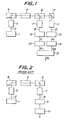
- reference numeral 1 is a light source made of LED
- 2 is an optical fiber forming a light beam transmission path
- 3 is a rod lens which causes distributed light beams to parallel light beams
- 4 is a polarizer which makes a light beam to a linear polarized light beam
- 5 is a Faraday's element made of Bi12SiO20 which causes the linear polarized light beam to rotate to give Faraday's effect depending on a given magnetic field strength
- 6 is an analyzer which separates a given linear polarized light beam into a S polarized light beam and a P polarized light beam.
- reference numeral 7 is a first rod lens for condensing parallel light beams of the analyzer 6, 8 is a first optical fiber forming a light beam transmission path, 9 is a first light beam-receiving element made of a photodiode for converting the S polarized light beam into an electric signal depending the strength thereof, 10 is a first calculation circuit for calculating and multiplicating the converted electric signal to exclude measuremental errors and the like resulting from losses in the light beam path, 11 is a second rod lens for condensing parallel light beams of the P polarized light beams separated at the analyzer 6, 12 is a second optical fiber forming a light beam transmission path, 13 is a second light beam receiving element made of a photodiode for converting the P polarized light beam into an electric signal depending on the strength thereof, and 14 is a second calculation circuit for calculating and multiplicating the converted electric signal to exclude measuremental errors and the like resulting from losses in the light beam path.
- the multiplication ratio in the first calculation circuit 10 is equal to
- a characteristic feature of the present invention is the provision of a third calculation circuit 15 which is supplied with the outputs from the first and second calculation circuits 10, 14 to perform a desired calculation so as to exclude measuremental errors resulting from temperature change.
- V11 -2(V e + ⁇ V e ⁇ T)Hl/(1-2 ⁇ 0 ⁇ Tl)
- V22 2(V e + ⁇ V e ⁇ T)Hl/(1+2 ⁇ 0 ⁇ Tl)
- V3 -2(V e + ⁇ V e ⁇ T)Hl ⁇ 1-2(2 ⁇ -1) ⁇ 0 ⁇ Tl ⁇
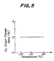
- the temperature of the sensor was varied in a range of -20°C through 80°C, and output change ratios relative to the output at 25°C were measured to evaluate the temperature characteristic property of the present sensor.
- the results are shown in Figs. 3a-3c.
- the output V3 of the third calculation circuit 15 which is a characteristic feature of the present invention was not at all influenced by temperature change, even when the outputs V11 and V22 of the first and second calculation circuits 9, 13 were influenced by the temperature change.
- the present optical magnetic field sensor can achieve measurements of a magnetic field strength with high precision, because it has further the third calculation circuit in addition to the structure of the optical magnetic field sensor having substantially the same structure as that of conventional one thereby to exclude measuremental errors caused by temperature change from the outputs obtained from the first and second calculation circuits by virtue of the determined the outputs treatment at the third calculation circuit. Moreover, measuremental errors caused by change of the amount of the light beam emanated from the light source and losses in the light beam transmission paths can be excluded because it performs calculations for regularization of the outputs at the first and second calculation circuits in the same fashion as in conventional ones.
Applications Claiming Priority (2)
| Application Number | Priority Date | Filing Date | Title |
|---|---|---|---|
| JP4035037A JPH0778526B2 (ja) | 1991-08-29 | 1992-02-21 | 光磁界センサ |
| JP35037/92 | 1992-02-21 |
Publications (3)
| Publication Number | Publication Date |
|---|---|
| EP0557090A2 true EP0557090A2 (de) | 1993-08-25 |
| EP0557090A3 EP0557090A3 (en) | 1994-06-08 |
| EP0557090B1 EP0557090B1 (de) | 1998-08-19 |
Family
ID=12430857
Family Applications (1)
| Application Number | Title | Priority Date | Filing Date |
|---|---|---|---|
| EP19930301189 Expired - Lifetime EP0557090B1 (de) | 1992-02-21 | 1993-02-18 | Optischer Magnetfeldsensor |
Country Status (4)
| Country | Link |
|---|---|
| EP (1) | EP0557090B1 (de) |
| AU (1) | AU643913B2 (de) |
| CA (1) | CA2089943C (de) |
| DE (1) | DE69320384T2 (de) |
Cited By (7)
| Publication number | Priority date | Publication date | Assignee | Title |
|---|---|---|---|---|
| EP0586226A2 (de) * | 1992-08-31 | 1994-03-09 | Ngk Insulators, Ltd. | Optischer Fühler für elektrische Felder |
| WO1994024572A1 (de) * | 1993-04-14 | 1994-10-27 | Siemens Aktiengesellschaft | Optisches messverfahren zum messen eines elektrischen wechselstromes mit temperaturkompensation und vorrichtung zur durchführung des verfahrens |
| WO1994024573A1 (de) * | 1993-04-14 | 1994-10-27 | Siemens Aktiengesellschaft | Optisches messverfahren zum messen eines elektrischen wechselstromes mit temperaturkompensation und vorrichtung zur durchführung des verfahrens |
| WO1996007922A1 (de) * | 1994-09-09 | 1996-03-14 | Siemens Aktiengesellschaft | Verfahren und vorrichtung zum messen eines elektrischen wechselstromes mit temperaturkompensation |
| DE4436181A1 (de) * | 1994-10-10 | 1996-04-11 | Siemens Ag | Verfahren und Vorrichtung zum Messen einer elektrischen Wechselgröße mit Temperaturkompensation durch Fitting |
| WO1997021108A2 (de) * | 1995-12-07 | 1997-06-12 | Siemens Aktiengesellschaft | Optisches messverfahren und optische messvorrichtung zum messen eines magnetischen wechselfeldes mit intensitätsnormierung |
| US5811964A (en) * | 1993-10-01 | 1998-09-22 | Siemens Aktiengelsellschaft | Method and device for measuring an electrical alternating quanity with temperature compensation |
Citations (2)
| Publication number | Priority date | Publication date | Assignee | Title |
|---|---|---|---|---|
| JPS6182179A (ja) | 1984-09-29 | 1986-04-25 | Toshiba Corp | 磁界計測方法 |
| US4973899A (en) | 1989-08-24 | 1990-11-27 | Sundstrand Corporation | Current sensor and method utilizing multiple layers of thin film magneto-optic material and signal processing to make the output independent of system losses |
Family Cites Families (5)
| Publication number | Priority date | Publication date | Assignee | Title |
|---|---|---|---|---|
| JPS59159076A (ja) * | 1983-03-02 | 1984-09-08 | Hitachi Ltd | 光学式磁界センサ |
| US4894608A (en) * | 1987-07-22 | 1990-01-16 | Square D Company | Electric current sensor using the faraday effect |
| JPH0670653B2 (ja) * | 1989-03-31 | 1994-09-07 | 日本碍子株式会社 | 光温度・電気量測定装置 |
| DE3923803A1 (de) * | 1989-07-19 | 1991-01-31 | Messwandler Bau Ag | Faseroptische anordnung zum messen der staerke eines elektrischen stromes |
| DE3924369A1 (de) * | 1989-07-22 | 1991-01-31 | Asea Brown Boveri | Verfahren zur messung eines elektrischen feldes oder einer elektrischen spannung und einrichtung zur durchfuehrung des verfahrens |
-
1993
- 1993-02-05 AU AU32842/93A patent/AU643913B2/en not_active Ceased
- 1993-02-18 DE DE1993620384 patent/DE69320384T2/de not_active Expired - Fee Related
- 1993-02-18 EP EP19930301189 patent/EP0557090B1/de not_active Expired - Lifetime
- 1993-02-19 CA CA 2089943 patent/CA2089943C/en not_active Expired - Fee Related
Patent Citations (2)
| Publication number | Priority date | Publication date | Assignee | Title |
|---|---|---|---|---|
| JPS6182179A (ja) | 1984-09-29 | 1986-04-25 | Toshiba Corp | 磁界計測方法 |
| US4973899A (en) | 1989-08-24 | 1990-11-27 | Sundstrand Corporation | Current sensor and method utilizing multiple layers of thin film magneto-optic material and signal processing to make the output independent of system losses |
Cited By (14)
| Publication number | Priority date | Publication date | Assignee | Title |
|---|---|---|---|---|
| EP0586226B1 (de) * | 1992-08-31 | 2000-01-19 | Ngk Insulators, Ltd. | Optischer Fühler für elektrische Felder |
| EP0586226A2 (de) * | 1992-08-31 | 1994-03-09 | Ngk Insulators, Ltd. | Optischer Fühler für elektrische Felder |
| US5656934A (en) * | 1993-04-14 | 1997-08-12 | Siemens Aktiengesellschaft | Optical method of measuring an alternating electrical current, including temperature compensation, and a device for carrying out the method |
| WO1994024572A1 (de) * | 1993-04-14 | 1994-10-27 | Siemens Aktiengesellschaft | Optisches messverfahren zum messen eines elektrischen wechselstromes mit temperaturkompensation und vorrichtung zur durchführung des verfahrens |
| WO1994024573A1 (de) * | 1993-04-14 | 1994-10-27 | Siemens Aktiengesellschaft | Optisches messverfahren zum messen eines elektrischen wechselstromes mit temperaturkompensation und vorrichtung zur durchführung des verfahrens |
| US5764046A (en) * | 1993-04-14 | 1998-06-09 | Siemens Atkiengesellschaft | Optical method and device for measuring an alternating electrical current with temperature compensation |
| US5811964A (en) * | 1993-10-01 | 1998-09-22 | Siemens Aktiengelsellschaft | Method and device for measuring an electrical alternating quanity with temperature compensation |
| US5847560A (en) * | 1994-09-09 | 1998-12-08 | Siemens Aktiengsellschaft | Process and device for measuring an alternating electric current with temperature compensation |
| WO1996007922A1 (de) * | 1994-09-09 | 1996-03-14 | Siemens Aktiengesellschaft | Verfahren und vorrichtung zum messen eines elektrischen wechselstromes mit temperaturkompensation |
| DE4436181A1 (de) * | 1994-10-10 | 1996-04-11 | Siemens Ag | Verfahren und Vorrichtung zum Messen einer elektrischen Wechselgröße mit Temperaturkompensation durch Fitting |
| US5895912A (en) * | 1994-10-10 | 1999-04-20 | Siemens Aktiengesellschaft | Method and device for measuring an alternating electric quantity with temperature compensation by fitting |
| WO1997021108A3 (de) * | 1995-12-07 | 1997-08-14 | Siemens Ag | Optisches messverfahren und optische messvorrichtung zum messen eines magnetischen wechselfeldes mit intensitätsnormierung |
| WO1997021108A2 (de) * | 1995-12-07 | 1997-06-12 | Siemens Aktiengesellschaft | Optisches messverfahren und optische messvorrichtung zum messen eines magnetischen wechselfeldes mit intensitätsnormierung |
| US6154022A (en) * | 1995-12-07 | 2000-11-28 | Siemens Ag | Optical measuring method and optical measuring device for measuring an alternating magnetic field having intensity normalization |
Also Published As
| Publication number | Publication date |
|---|---|
| DE69320384D1 (de) | 1998-09-24 |
| CA2089943A1 (en) | 1993-08-22 |
| AU643913B2 (en) | 1993-11-25 |
| AU3284293A (en) | 1993-08-26 |
| CA2089943C (en) | 1997-11-11 |
| DE69320384T2 (de) | 1999-02-04 |
| EP0557090B1 (de) | 1998-08-19 |
| EP0557090A3 (en) | 1994-06-08 |
Similar Documents
| Publication | Publication Date | Title |
|---|---|---|
| EP0210716B1 (de) | Driftkompensationstechnik für einen magnetooptischen Stromsensor | |
| EP0088419B1 (de) | Vorrichtung zur optischen Messung eines Stromes | |
| US5696858A (en) | Fiber Optics apparatus and method for accurate current sensing | |
| JP3791975B2 (ja) | ホモダイン干渉受信計及びその受信法 | |
| EP0361832B1 (de) | Elektrooptisches Spannungsdifferenz-Messverfahren und -Gerät in einem Messsystem für phasenverschobene Signale | |
| EP0706661B1 (de) | Optisches messverfahren zum messen eines elektrischen wechselstromes mit temperaturkompensation und vorrichtung zur durchführung des verfahrens | |
| US5811964A (en) | Method and device for measuring an electrical alternating quanity with temperature compensation | |
| US5382901A (en) | Optical magnetic field sensor capable of precise measurement without temperature induced errors | |
| EP0557090A2 (de) | Optischer Magnetfeldsensor | |
| KR100310374B1 (ko) | 패러데이 효과를 이용해서 2개의 반대방향 광신호로전류를측정하기위한방법및장치 | |
| KR100979215B1 (ko) | 편광계의 고정밀 교정 | |
| US5895912A (en) | Method and device for measuring an alternating electric quantity with temperature compensation by fitting | |
| JP2001513893A (ja) | 電圧を測定するための方法と装置 | |
| DE19544778A1 (de) | Verfahren und Anordnung zum Messen einer Meßgröße, insbesondere eines elektrischen Stromes, mit hoher Meßauflösung | |
| JP3342768B2 (ja) | 光ファイバ型計測装置及び計測方法 | |
| JPH08178968A (ja) | 光ファイバ型計測装置及び計測方法 | |
| Semel | A proposal for a solar magnetograph | |
| Murooka et al. | High‐sensitive Pockels field sensor with a dielectric mirror | |
| CN109990822B (zh) | 一种光电探测模块的频率响应标定装置及方法 | |
| EP0668613A1 (de) | Methode zur bestimmung der sauerstoffkonzentration in siliziumkristallen | |
| JPH10197570A (ja) | 光ファイバ電流計測装置 | |
| JP3011244B2 (ja) | 光応用直流電流変成器 | |
| SU1582157A1 (ru) | Способ калибровки селективных измерительных приборов | |
| SU1613981A1 (ru) | Способ измерени напр женности импульсного, электрического и магнитного полей | |
| JPH0282137A (ja) | レーザ方式ガスセンサ |
Legal Events
| Date | Code | Title | Description |
|---|---|---|---|
| PUAI | Public reference made under article 153(3) epc to a published international application that has entered the european phase |
Free format text: ORIGINAL CODE: 0009012 |
|
| AK | Designated contracting states |
Kind code of ref document: A2 Designated state(s): DE FR GB |
|
| PUAL | Search report despatched |
Free format text: ORIGINAL CODE: 0009013 |
|
| AK | Designated contracting states |
Kind code of ref document: A3 Designated state(s): DE FR GB |
|
| 17P | Request for examination filed |
Effective date: 19941004 |
|
| 17Q | First examination report despatched |
Effective date: 19970313 |
|
| GRAG | Despatch of communication of intention to grant |
Free format text: ORIGINAL CODE: EPIDOS AGRA |
|
| GRAG | Despatch of communication of intention to grant |
Free format text: ORIGINAL CODE: EPIDOS AGRA |
|
| GRAH | Despatch of communication of intention to grant a patent |
Free format text: ORIGINAL CODE: EPIDOS IGRA |
|
| GRAH | Despatch of communication of intention to grant a patent |
Free format text: ORIGINAL CODE: EPIDOS IGRA |
|
| GRAA | (expected) grant |
Free format text: ORIGINAL CODE: 0009210 |
|
| AK | Designated contracting states |
Kind code of ref document: B1 Designated state(s): DE FR GB |
|
| REF | Corresponds to: |
Ref document number: 69320384 Country of ref document: DE Date of ref document: 19980924 |
|
| ET | Fr: translation filed | ||
| PLBE | No opposition filed within time limit |
Free format text: ORIGINAL CODE: 0009261 |
|
| STAA | Information on the status of an ep patent application or granted ep patent |
Free format text: STATUS: NO OPPOSITION FILED WITHIN TIME LIMIT |
|
| 26N | No opposition filed | ||
| PGFP | Annual fee paid to national office [announced via postgrant information from national office to epo] |
Ref country code: GB Payment date: 20000208 Year of fee payment: 8 |
|
| PGFP | Annual fee paid to national office [announced via postgrant information from national office to epo] |
Ref country code: FR Payment date: 20000219 Year of fee payment: 8 Ref country code: DE Payment date: 20000219 Year of fee payment: 8 |
|
| PG25 | Lapsed in a contracting state [announced via postgrant information from national office to epo] |
Ref country code: GB Free format text: LAPSE BECAUSE OF NON-PAYMENT OF DUE FEES Effective date: 20010218 |
|
| GBPC | Gb: european patent ceased through non-payment of renewal fee |
Effective date: 20010218 |
|
| PG25 | Lapsed in a contracting state [announced via postgrant information from national office to epo] |
Ref country code: FR Free format text: LAPSE BECAUSE OF NON-PAYMENT OF DUE FEES Effective date: 20011031 |
|
| REG | Reference to a national code |
Ref country code: FR Ref legal event code: ST |
|
| PG25 | Lapsed in a contracting state [announced via postgrant information from national office to epo] |
Ref country code: DE Free format text: LAPSE BECAUSE OF NON-PAYMENT OF DUE FEES Effective date: 20011201 |