EP0556703B1 - Hydraulic engine damper with two chambers - Google Patents
Hydraulic engine damper with two chambers Download PDFInfo
- Publication number
- EP0556703B1 EP0556703B1 EP93102071A EP93102071A EP0556703B1 EP 0556703 B1 EP0556703 B1 EP 0556703B1 EP 93102071 A EP93102071 A EP 93102071A EP 93102071 A EP93102071 A EP 93102071A EP 0556703 B1 EP0556703 B1 EP 0556703B1
- Authority
- EP
- European Patent Office
- Prior art keywords
- chamber
- spring bodies
- bent
- diaphragm plate
- plate
- Prior art date
- Legal status (The legal status is an assumption and is not a legal conclusion. Google has not performed a legal analysis and makes no representation as to the accuracy of the status listed.)
- Expired - Lifetime
Links
Images

Classifications
-
- F—MECHANICAL ENGINEERING; LIGHTING; HEATING; WEAPONS; BLASTING
- F16—ENGINEERING ELEMENTS AND UNITS; GENERAL MEASURES FOR PRODUCING AND MAINTAINING EFFECTIVE FUNCTIONING OF MACHINES OR INSTALLATIONS; THERMAL INSULATION IN GENERAL
- F16F—SPRINGS; SHOCK-ABSORBERS; MEANS FOR DAMPING VIBRATION
- F16F1/00—Springs
- F16F1/36—Springs made of rubber or other material having high internal friction, e.g. thermoplastic elastomers
- F16F1/42—Springs made of rubber or other material having high internal friction, e.g. thermoplastic elastomers characterised by the mode of stressing
- F16F1/422—Springs made of rubber or other material having high internal friction, e.g. thermoplastic elastomers characterised by the mode of stressing the stressing resulting in flexion of the spring
-
- F—MECHANICAL ENGINEERING; LIGHTING; HEATING; WEAPONS; BLASTING
- F16—ENGINEERING ELEMENTS AND UNITS; GENERAL MEASURES FOR PRODUCING AND MAINTAINING EFFECTIVE FUNCTIONING OF MACHINES OR INSTALLATIONS; THERMAL INSULATION IN GENERAL
- F16F—SPRINGS; SHOCK-ABSORBERS; MEANS FOR DAMPING VIBRATION
- F16F13/00—Units comprising springs of the non-fluid type as well as vibration-dampers, shock-absorbers, or fluid springs
- F16F13/04—Units comprising springs of the non-fluid type as well as vibration-dampers, shock-absorbers, or fluid springs comprising both a plastics spring and a damper, e.g. a friction damper
- F16F13/06—Units comprising springs of the non-fluid type as well as vibration-dampers, shock-absorbers, or fluid springs comprising both a plastics spring and a damper, e.g. a friction damper the damper being a fluid damper, e.g. the plastics spring not forming a part of the wall of the fluid chamber of the damper
- F16F13/08—Units comprising springs of the non-fluid type as well as vibration-dampers, shock-absorbers, or fluid springs comprising both a plastics spring and a damper, e.g. a friction damper the damper being a fluid damper, e.g. the plastics spring not forming a part of the wall of the fluid chamber of the damper the plastics spring forming at least a part of the wall of the fluid chamber of the damper
- F16F13/10—Units comprising springs of the non-fluid type as well as vibration-dampers, shock-absorbers, or fluid springs comprising both a plastics spring and a damper, e.g. a friction damper the damper being a fluid damper, e.g. the plastics spring not forming a part of the wall of the fluid chamber of the damper the plastics spring forming at least a part of the wall of the fluid chamber of the damper the wall being at least in part formed by a flexible membrane or the like
- F16F13/105—Units comprising springs of the non-fluid type as well as vibration-dampers, shock-absorbers, or fluid springs comprising both a plastics spring and a damper, e.g. a friction damper the damper being a fluid damper, e.g. the plastics spring not forming a part of the wall of the fluid chamber of the damper the plastics spring forming at least a part of the wall of the fluid chamber of the damper the wall being at least in part formed by a flexible membrane or the like characterised by features of partitions between two working chambers
- F16F13/106—Design of constituent elastomeric parts, e.g. decoupling valve elements, or of immediate abutments therefor, e.g. cages
-
- F—MECHANICAL ENGINEERING; LIGHTING; HEATING; WEAPONS; BLASTING
- F16—ENGINEERING ELEMENTS AND UNITS; GENERAL MEASURES FOR PRODUCING AND MAINTAINING EFFECTIVE FUNCTIONING OF MACHINES OR INSTALLATIONS; THERMAL INSULATION IN GENERAL
- F16F—SPRINGS; SHOCK-ABSORBERS; MEANS FOR DAMPING VIBRATION
- F16F2236/00—Mode of stressing of basic spring or damper elements or devices incorporating such elements
- F16F2236/02—Mode of stressing of basic spring or damper elements or devices incorporating such elements the stressing resulting in flexion of the spring
Definitions
- the invention relates to a hydraulically damping two-chamber engine mount, the chambers of which are filled with liquid and have rubber-elastic circumferential walls are connected to one another via a channel arranged in a rigid intermediate plate, and in the intermediate plate of which a chamber which is at least centrally open on the end face is embedded, in which one membrane plate is clamped on both sides by liquid and is movable parallel to the direction of vibrations.
- the function of the membrane plate as a so-called decoupling membrane in hydraulic bearings is to hydraulically "decouple" the low-amplitude vibrations introduced, i.e. not to let the hydraulic overflow channel take effect.
- the bearing is thus soft for vibrations of small amplitude, so that the additional deformation resistance caused by the hydraulic damping does not come into play. Only when the membrane hits the stop does liquid flow through the overflow channel, causing damping and increased rigidity.
- Such membranes must therefore be easy to move, they should not abruptly touch the cage wall, but be provided with a progressive identifier and must largely prevent fluid exchange between the working and compensation chambers, so that they do not form a bypass for the main channel of the bearing.
- the storage and clamping of the membrane plate therefore poses a particular problem for the designer.
- the bearing has its original volume stiffness, as it results without a decoupling membrane.
- the largely rigid membrane plate on the outer circumference is connected via a thin, horizontally circumferential, concentric web made of rubber with a toroidal rubber ring, the diameter of which is slightly larger than the free height of the membrane chamber in which this rubber ring is then clamped.
- Such an arrangement allows a very soft mounting of the membrane plate, but then requires very thin and therefore mechanically less resistant rubber layers for the thrust element.
- such an arrangement requires additional, soft, progressive stops so that the decoupling only works for vibrations of small amplitudes.
- the present invention has for its object to provide a hydraulically damping two-chamber engine mount, the diaphragm plate is easy to move, does not rattle and progressively adjoins its boundary surfaces, i.e. a hydraulic bearing that a smooth transition of the pV characteristic from almost a horizontal area to a sloping area.
- the membrane plate made of rigid material has several holes in the area near the edge into which thin-walled, roll-membrane-like spring bodies made of rubber-elastic material of approximately hat-shaped shape with a bent back edge are inserted such that they move the membrane plate up and down protrude in such a way that the hat-shaped tips of the spring bodies are constantly in contact with the opposite, horizontal boundary surface of the membrane chamber, while the bent-back edges end at a distance from their boundary surface.
- the height of the bent back edge is expediently a maximum of one third to one quarter of the total height of the spring body.
- the spring bodies are expediently vulcanized with their bent back edge on the top or the bottom of the membrane plate.
- the spring bodies in the end region of the bent-back edge may have on their outside two webs which run parallel to one another at a spacing of the membrane disk thickness and via which they are clipped onto the respective bore edges on the membrane plate.
- the spring bodies are fastened alternately from bore to bore once on the upper side and once on the underside of the membrane plate and the central, hat-shaped middle part of the spring bodies alternately passes through the bores on one side or the other.
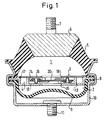
- the two-chamber engine mount initially has, in a conventional manner, an upper, engine-side chamber 1 and a lower compensating chamber 2, which are connected to one another via a channel 4 running in an intermediate plate 3.
- the upper chamber 1 is delimited by a thick-walled, hollow-conical chamber wall 5, the so-called suspension spring, which has a bearing plate 6 on the upper end face with a bolt 7 for fixing to the motor (not shown in more detail).
- the lower chamber 2 is formed by a cup-shaped chamber wall 8, for example, which is also made of rubber-elastic, but more volume-compliant material than that of the chamber wall 5, since the chamber 2 functions practically only as a compensating chamber. All bearing parts are clamped to one another in a liquid-tight manner via a circumferential ring flange 9, the ring flange 9 simultaneously capturing the lower housing cover 10 with a connecting bolt 11 for fixing the bearing to the vehicle body.
- the intermediate plate 3 consists of a base plate 12, into which the annular connecting channel 4 is cut to the underside with a passage opening 13 indicated by dashed lines. Furthermore, the base plate 12 has a central, cylindrical recess 14, the underside of which is provided with a central opening 15 or corresponding openings. The recesses 4 and 14 cut into the base plate 12 can then be closed by a centrally placed cover plate 16, this cover plate 16 having an opening 17 indicated by dashed lines as a connection from the ring channel 4 to the upper chamber 1 and a central opening 18 above the membrane chamber 14.
- the membrane plate 20 consists of rigid material, such as plastic or aluminum, the membrane plate 20 having a slightly smaller diameter than the inside diameter of the membrane chamber 14.
- this membrane plate 20 as can be seen in particular from the top view according to FIG. 2 - several holes 21 - 26 are cut symmetrically to one another in the area near the edge.
- these holes 21-26 are now - as you can see in particular from the enlarged longitudinal section of FIG. 3 according to the cutting line III - III according to FIG. 2 recognizes - thin-walled hollow spring bodies 31 - 36 made of rubber-elastic material used in a manner still to be explained.
- These spring diaphragm-like spring bodies 31-36 have an approximately hat-shaped shape with a bent-back edge 41, the height of which is approximately one third to one quarter of the total height of a spring body.
- These spring bodies 31-36 are now expediently fastened alternately with their tips up or down on the top or bottom of the membrane plate 20 with their bent back edge 41 adjacent to the respective bore edge 21-26 by vulcanization. They can be vulcanized directly onto the membrane plate 20 in a single vulcanization process.
- the size and design of the individual spring bodies is to be dimensioned such that the hat-shaped tips 42 each abut the opposite horizontal boundary surface 37 or 38 of the membrane chamber 14, while the underside 43 of the bent-back edge 41 is at a distance from its respective opposite boundary surface 38 or 37 ends.
- the system acts in the same way when the diaphragm plate 20 moves upward through the oppositely installed spring bodies 32, 34 and 36.
- spring bodies 45 A further type of fastening of spring bodies 45 is shown in the partial section according to FIG. 4. These spring bodies 45 have in the end region of their bent-back edge 46 on their outside two circumferential projections 47 and 48 which run at a distance corresponding to the thickness of the membrane plate 20. The spring bodies 45 designed in this way can then be clipped very easily into the bores 21-26 of the membrane plate 20.
- spring bodies are provided on the periphery of the membrane plate.
- any other number of spring bodies is also possible, an even number of spring bodies being expediently chosen in order to enable mutual installation.
Description
Die Erfindung bezieht sich auf ein hydraulisch dämpfendes Zweikammer-Motorlager, dessen mit Flüssigkeit gefüllte und gummielastische Umfangswände aufweisende Kammern über einen, in einer starren Zwischenplatte angeordneten Kanal miteinander in Verbindung stehen und in dessen Zwischenplatte eine stirnseitig zumindest zentral offene Kammer eingelassen ist, in der eine beiderseits von Flüssigkeit beaufschlagte und parallel zur Richtung eingeleiteter Schwingungen bewegliche Membranplatte eingespannt ist.The invention relates to a hydraulically damping two-chamber engine mount, the chambers of which are filled with liquid and have rubber-elastic circumferential walls are connected to one another via a channel arranged in a rigid intermediate plate, and in the intermediate plate of which a chamber which is at least centrally open on the end face is embedded, in which one membrane plate is clamped on both sides by liquid and is movable parallel to the direction of vibrations.
Die Membranplatte als sogenannte Entkopplungsmembran hat in Hydrolagern die Aufgabe, die eingeleiteten Schwingungen geringer Amplitude hydraulisch zu "entkoppeln", d.h. den hydraulischen Überströmkanal nicht wirksam werden zu lassen. Damit ist das Lager für Schwingungen kleiner Amplitude weich, so daß der durch die hydraulische Dämpfung hervorgerufene zusätzliche Verformungswiderstand nicht zum Tragen kommt. Erst wenn die Membran am Anschlag ist, strömt auch Flüssigkeit durch den Überströmkanal und bewirkt Dämpfung und eine erhöhte Steifigkeit.The function of the membrane plate as a so-called decoupling membrane in hydraulic bearings is to hydraulically "decouple" the low-amplitude vibrations introduced, i.e. not to let the hydraulic overflow channel take effect. The bearing is thus soft for vibrations of small amplitude, so that the additional deformation resistance caused by the hydraulic damping does not come into play. Only when the membrane hits the stop does liquid flow through the overflow channel, causing damping and increased rigidity.
Solche Membranen müssen demnach leicht beweglich sein, sie sollen sich nicht schlagartig an die Käfigwand anlegen, sondern mit einer progressiven Kennung versehen sein und müssen weitgehend einen Flüssigkeitsaustausch zwischen Arbeits- und Ausgleichskammer unterbinden, so daß sie nicht einen Bypass für den Hauptkanal des Lagers bilden. Daher bereitet die Lagerung und Einspannung der Membranplatte dem Konstrukteur ein besonderes Problem.Such membranes must therefore be easy to move, they should not abruptly touch the cage wall, but be provided with a progressive identifier and must largely prevent fluid exchange between the working and compensation chambers, so that they do not form a bypass for the main channel of the bearing. The storage and clamping of the membrane plate therefore poses a particular problem for the designer.
Bei einem hydraulisch gedämpften Motorlager ohne Entkopplungsmembran stellt sich bei geschlossenem Kanal das Druck/Volumen-Diagramm bei Einfederung praktisch als Gerade mit konstanter Steigung dar. Bei einem Lager mit einer losen Entkopplungsmembran verläuft diese pV-Kennlinie bei einer geringen Einfederung zunächst nahezu horizontal, bis der Freiweg der Membran durchmessen ist und die Membranplatte an der gegenüberliegenden Käfigwand anschlägt.In the case of a hydraulically damped engine mount without a decoupling diaphragm, the pressure / volume diagram for deflection is practically a straight line with constant slope when the duct is closed. In the case of a bearing with a loose decoupling diaphragm, this pV characteristic curve initially runs almost horizontally with a small deflection until the Clearance of the membrane is measured and the membrane plate strikes the opposite cage wall.
Von diesem Punkt an hat das Lager wieder seine ursprüngliche Volumensteifigkeit, wie sie sich ohne Entkopplungsmembran ergibt. Ein Lager mit einer solchen frei beweglichen Membranplatte, wie sie beispielsweise in der DE 27 27 244 A1 beschrieben ist, bietet zwar eine optimale Entkopplung für kleine Amplituden, hat aber den großen Nachteil, daß sie bei größeren Amplituden durch Anschlagen an ihre Begrenzungsflächen Geräusche verursacht, die sich als störendes Klappern oder Klopfen äußern.From this point on, the bearing has its original volume stiffness, as it results without a decoupling membrane. A bearing with such a freely movable membrane plate, as described, for example, in DE 27 27 244 A1, offers optimal decoupling for small amplitudes, but has the major disadvantage that it causes noise at larger amplitudes by striking its boundary surfaces, which manifest themselves as annoying rattling or knocking.
Es ist daher versucht worden, diese Anschlaggeräusche dadurch zu unterbinden, daß die Membranplatte zwischen 2 Gummiringen am äußeren Umfang auf der Ober- und Unterseite eingespannt ist, wie ebenfalls in der DE 27 27 244 A1 beschrieben.It has therefore been attempted to prevent this stop noise by the membrane plate between 2 rubber rings is clamped on the outer circumference on the top and bottom, as also described in DE 27 27 244 A1.
Eine solche elastische Membranlagerung über druckbeaufschlagte Gummielemente hat aber erhebliche herstellungstechnische Schwierigkeiten für das Lager. Darüberhinaus ist die Entkopplungsfunktion, die ja für kleine Amplituden einer sehr weichen Membranaufhängung (Steifigkeit nahezu 0) bedarf, nur schwer reproduzierbar einzustellen.Such an elastic membrane bearing over pressurized rubber elements has considerable manufacturing difficulties for the bearing. In addition, the decoupling function, which requires a very soft membrane suspension (stiffness almost 0) for small amplitudes, is difficult to set reproducibly.
Berücksichtigt man nämlich die üblichen Maße der Membranplatte (etwa 1,5 - 2,5 mm dick) und des Membrankäfigs von etwa 5 - 6 mm Höhe, so ist daraus ersichtlich, daß sowohl die progressiv wirkenden Druckanschläge als auch der Membrankäfig für eine einwandfreie Funktion des Systems mit außerordentlich geringen Toleranzen hergestellt werden müssen, da schon Abweichungen von 1/10 bis 2/10 mm die Membranplatte entweder zum Klappern bringen oder so stramm verspannen, daß eine hinreichend freie Bewegung der Membranplatte über typische Wege von 2/10 bis 3/10 mm und damit die gewünschte hydraulische Entkopplung nicht mehr gegeben ist.If one takes into account the usual dimensions of the membrane plate (about 1.5 - 2.5 mm thick) and the membrane cage of about 5 - 6 mm high, it can be seen that both the progressively acting pressure stops and the membrane cage for perfect function of the system must be manufactured with extremely small tolerances, since deviations of 1/10 to 2/10 mm either cause the membrane plate to rattle or tighten so tightly that sufficient free movement of the membrane plate over typical paths from 2/10 to 3 / 10 mm and thus the desired hydraulic decoupling is no longer given.
Eine für die Entkopplung bessere Lösung, die weniger abhängig von Fertigungstoleranzen ist, bietet die Membranlagerung mit Schubelementen, wie sie beispielsweise in der DE 37 31 524 A1 beschrieben ist.A better solution for the decoupling, which is less dependent on manufacturing tolerances, is provided by the membrane bearing with thrust elements, as described for example in
Dabei ist die weitgehend starre Membranplatte am äußeren Umfang über einen dünnen, horizontal umlaufenden, konzentrischen Steg aus Gummi mit einem torusförmigen Gummiring verbunden, dessen Durchmesser geringfügig größer als die freie Höhe der Membrankammer ist, in die dieser Gummiring dann eingespannt wird.The largely rigid membrane plate on the outer circumference is connected via a thin, horizontally circumferential, concentric web made of rubber with a toroidal rubber ring, the diameter of which is slightly larger than the free height of the membrane chamber in which this rubber ring is then clamped.
Eine solche Anordnung erlaubt eine sehr weiche Lagerung der Membranplatte, erfordert dann aber sehr dünne und daher mechanisch wenig widerstandsfähige Gummischichten für das Schubelement. Zudem bedarf eine solche Anordnung noch zusätzlicher, weich einsetzender, progressiver Anschläge, damit die Entkopplung nur für Schwingungen kleiner Amplituden wirkt.Such an arrangement allows a very soft mounting of the membrane plate, but then requires very thin and therefore mechanically less resistant rubber layers for the thrust element. In addition, such an arrangement requires additional, soft, progressive stops so that the decoupling only works for vibrations of small amplitudes.
Bei diesem Membrantyp ergeben sich oft Probleme mit der dynamischen Dauerfestigkeit, da wegen der auftretenden Durckdifferenzen im Lager, die für große Amplituden zwischen + 3 bar und - 1 bar schwanken können, starke Spannungsspitzen im schub-belasteten Übergangsbereich des Elementes entstehen, was leicht zum Einreißen oder Abscheren führt.With this type of membrane there are often problems with the dynamic fatigue strength, because due to the pressure differences occurring in the bearing, which can fluctuate between + 3 bar and - 1 bar for large amplitudes, strong voltage peaks occur in the shear-stressed transition area of the element, which is easy to tear or shearing leads.
Ausgehend von dem eingangs genannten Stand der Technik und der geschilderten Problematik liegt der vorliegenden Erfindung die Aufgabe zugrunde, ein hydraulisch dämpfendes Zweikammer-Motorlager zu schaffen, dessen Membranplatte leicht beweglich ist, nicht klappert und sich progressiv an ihre Begrenzungsflächen anlegt, d.h. ein Hydrolager, das einen weichen Übergang der pV-Kennlinie von nahezu horizontal verlaufendem Bereich zum schräg ansteigendem Bereich aufweist.Based on the prior art mentioned above and the problems outlined, the present invention has for its object to provide a hydraulically damping two-chamber engine mount, the diaphragm plate is easy to move, does not rattle and progressively adjoins its boundary surfaces, i.e. a hydraulic bearing that a smooth transition of the pV characteristic from almost a horizontal area to a sloping area.
Zur Lösung dieser Aufgabe ist erfindungsgemäß vorgesehen, daß die aus starrem Material bestehende Membranplatte im randnahen Bereich mehrere Bohrungen aufweist, in die dünnwandige, rollmembranähnliche Federkörper aus gummielastischem Material von etwa hutförmiger Gestalt mit zurückgebogenem Rand derart eingesetzt sind, daß sie die Membranplatte nach oben und unten überragen derart, daß die hutförmigen Spitzen der Federkörper ständig in Kontakt mit der gegenüberliegenden, horizontalen Begrenzungsfläche der Membrankammer stehen, während die zurückgebogenen Ränder im Abstand zu ihrer Begrenzungsfläche enden.To solve this problem it is provided according to the invention that the membrane plate made of rigid material has several holes in the area near the edge into which thin-walled, roll-membrane-like spring bodies made of rubber-elastic material of approximately hat-shaped shape with a bent back edge are inserted such that they move the membrane plate up and down protrude in such a way that the hat-shaped tips of the spring bodies are constantly in contact with the opposite, horizontal boundary surface of the membrane chamber, while the bent-back edges end at a distance from their boundary surface.
Mit derartigen hutförmigen, dünnwandigen Federkörpern ist eine Halterung und Einspannung der Membranplatte geschaffen, die ein weiches und leichtes Ansprechen der Membranplatte auf eingeleitete hochfrequente Schwingungen erlaubt und die bei zunehmender Verformung der Federkörper und einem Anlegen der zurückgebogenen Ränder an ihre Begrenzungsfläche ein progressives Abbremsen der Bewegung der Membranplatte bewirkt und damit sicher verhindert, daß die Membranplatte gegen ihre Begrenzungen anschlägt und klappert.With such hat-shaped, thin-walled spring bodies, a mounting and clamping of the membrane plate is created, which allows a soft and easy response of the membrane plate to initiated high-frequency vibrations and which, with increasing deformation of the spring bodies and application of the bent-back edges to their boundary surface, progressively brakes the movement of the Membrane plate causes and thus reliably prevents the membrane plate from hitting and clattering against its limits.
Zweckmäßigerweise beträgt die Höhe des zurückgebogenen Randes maximal ein Drittel bis ein Viertel der Gesamthöhe des Federkörpers.The height of the bent back edge is expediently a maximum of one third to one quarter of the total height of the spring body.
Die Federkörper sind dabei zweckmäßigerweise mit ihrem zurückgebogenen Rand auf der Ober- oder der Unterseite der Membranplatte anvulkanisiert.The spring bodies are expediently vulcanized with their bent back edge on the top or the bottom of the membrane plate.
Es ist aber auch möglich, daß die Federkörper im Endbereich des zurückgebogenen Randes auf ihrer Außenseite zwei, im Abstand der Membranscheibendicke parallel zueinander umlaufende Stege aufweisen, über die sie an den jeweiligen Bohrungsrändern an der Membranplatte eingeklipst sind.However, it is also possible for the spring bodies in the end region of the bent-back edge to have on their outside two webs which run parallel to one another at a spacing of the membrane disk thickness and via which they are clipped onto the respective bore edges on the membrane plate.
Ferner ist es von Vorteil, wenn die Federkörper von Bohrung zu Bohrung abwechselnd einmal auf der Oberseite und einmal auf der Unterseite der Membranplatte befestigt sind und der zentrale, hutförmige Mittelteil der Federkörper die Bohrungen abwechselnd nach der einen oder der anderen Seite durchsetzt. Durch eine solche abwechselnde Anordnung wird die Membranplatte im unbelasteten Zustand stets mittig in der Membrankammer gehalten und es erfolgt ein weiches und kontinuierliches Ansprechen der Platte auf eingeleitete Schwingungen.It is also advantageous if the spring bodies are fastened alternately from bore to bore once on the upper side and once on the underside of the membrane plate and the central, hat-shaped middle part of the spring bodies alternately passes through the bores on one side or the other. Through such an alternating arrangement, the membrane plate is always held in the center of the membrane chamber in the unloaded state and there is a soft and continuous response of the plate to initiated vibrations.
Anhand einer schematischen Zeichnung sind Aufbau und Funktionsweise eines Ausführungsbeispiels nach der Erfindung näher erläutert. Dabei zeigen:
- Fig. 1
- einen Längsschnitt durch das Grundprinzip eines solchen hydraulisch dämpfenden Motorlagers,
- Fig. 2
- eine Aufsicht auf eine Membranplatte mit eingesetzten Federkörpern,
- Fig. 3
- einen Längsschnitt durch die Zwischenplatte mit Membranplatte entsprechend Fig. 1 im Ausschnitt und in vergrößertem Maßstab und entsprechend der Schnittlinie III - III nach Fig.2 und
- Fig. 4
- einen Teilausschnitt mit eingeklipsten Federkörpern.
- Fig. 1
- a longitudinal section through the basic principle of such a hydraulically damping engine mount,
- Fig. 2
- a top view of a membrane plate with inserted spring bodies,
- Fig. 3
- a longitudinal section through the intermediate plate with membrane plate according to Fig. 1 in a detail and on an enlarged scale and according to the section line III - III of Fig.2 and
- Fig. 4
- a partial section with clipped spring bodies.
Wie man aus Figur 1 ersieht, weist das Zweikammer-Motorlager zunächst in herkömmlicher Weise eine obere, motorseitige Kammer 1 und eine untere Ausgleichskammer 2 auf, die über einen, in einer Zwischenplatte 3 verlaufenden Kanal 4 miteinander in Verbindung stehen. Die obere Kammer 1 wird von einer starkwandigen, hohlkegelförmigen Kammerwandung 5, der sog. Tragfeder, begrenzt, die an der oberen Stirnseite eine Lagerplatte 6 mit einem Bolzen 7 zur Festlegung am nicht näher dargestellten Motor aufweist. Die untere Kammer 2 ist von einer beispielsweise tassenförmigen Kammerwandung 8 aus ebenfalls gummielastischem, jedoch volumennachgiebigerem Material als das der Kammerwandung 5 gebildet, da die Kammer 2 praktisch nur als Ausgleichskammer fungiert. Alle Lagerteile sind über einen umlaufenden Ringflansch 9 flüssigkeitsdicht miteinander verspannt, wobei der Ringflansch 9 gleichzeitig den unteren Gehäusedeckel 10 mit einem Anschlußbolzen 11 zur Festlegung des Lagers an die Fahrzeugkarosserie mit erfaßt.As can be seen from FIG. 1, the two-chamber engine mount initially has, in a conventional manner, an upper, engine-
Nach dem dargestellten Ausführungsbeispiel besteht die Zwischenplatte 3 aus einer Bodenplatte 12, in die der ringförmige Verbindungskanal 4 mit einer gestrichelt angedeuteten Durchtrittsöffnung 13 zur Unterseite eingeschnitten ist. Ferner weist die Bodenplatte 12 eine zentrale, zylindrische Ausnehmung 14 auf, deren Unterseite mit einer zentralen Öffnung 15 oder entsprechenden Durchbrüchen versehen ist. Die in die Bodenplatte 12 eingeschnittenen Ausnehmungen 4 und 14 können dann durch eine zentrisch aufgesetzte Deckplatte 16 verschlossen sein, wobei diese Deckplatte 16 eine gestrichelt angedeutete Öffnung 17 als Verbindung vom Ringkanal 4 zur oberen Kammer 1 und eine zentrale Öffnung 18 oberhalb der Membrankammer 14 aufweist.According to the illustrated embodiment, the
In die somit durch die Ausnehmung 14 gebildete Kammer ist nunmehr eine kreiszylindrische Membranplatte 20 eingesetzt, die im vergrößerten Maßstab anhand Figur 2 und 3 im einzelnen erläutert wird.In the chamber thus formed by the
Die Membranplatte 20 besteht aus starrem Material, wie beispielsweise Kunststoff oder Aluminium, wobei die Membranplatte 20 einen geringfügig kleineren Durchmesser als den Innendurchmesser der Membrankammer 14 aufweist. In diese Membranplatte 20 sind - wie man insbesondere aus der Aufsicht nach Fig. 2 ersieht - im randnahen Bereich mehrere Bohrungen 21 - 26 symmetrisch zueinander eingeschnitten. In diese Bohrungen 21- 26 sind nunmehr - wie man insbesondere aus dem vergrößerten Längsschnitt nach Fig. 3 entsprechend der Schnittlinie III - III nach Fig. 2 erkennt - dünnwandige hohle Federkörper 31 - 36 aus gummielastischem Material in noch zu erläuternder Weise eingesetzt.The
Diese rollmembranähnlichen Federkörper 31 - 36 haben eine etwa hutförmige Gestalt mit einem zurückgebogenen Rand 41, dessen Höhe etwa ein Drittel bis ein Viertel der Gesamthöhe eines Federkörpers beträgt. Diese Federkörper 31 - 36 sind nunmehr abwechselnd mit ihrer Spitze nach oben oder unten jeweils auf der Oberseite oder der Unterseite der Membranplatte 20 mit ihrem zurückgebogenen Rand 41 an den jeweiligen Bohrungsrand 21 - 26 angrenzend zweckmäßigerweise durch Vulkanisation befestigt. Sie können dabei in einem einzigen Vulkanisationsprozeß unmittelbar an die Membranplatte 20 anvulkanisiert werden. Die Größe und Gestaltung der einzelnen Federkörper ist dabei so zu bemessen, daß die hutförmigen Spitzen 42 jeweils an der gegenüberliegenden horizontalen Begrenzungsfläche 37 bzw. 38 der Membrankammer 14 anliegen, während die Unterseite 43 des zurückgebogenen Randes 41 im Abstand von ihrer jeweiligen gegenüberliegenden Begrenzungsfläche 38 bzw. 37 endet.These spring diaphragm-like spring bodies 31-36 have an approximately hat-shaped shape with a bent-back edge 41, the height of which is approximately one third to one quarter of the total height of a spring body. These spring bodies 31-36 are now expediently fastened alternately with their tips up or down on the top or bottom of the
Bei einer Schwingungseinleitung von oben werden dann die Federkörper 31, 33 und 35, deren Spitzen 42 auf der unteren Begrenzungsfläche 37 aufruhen, sanft zusammengepreßt, bis die Unterseiten 43 der umgekehrt eingebauten Federkörper 32, 34 und 36 mit der Begrenzungsfläche 37 in Kontakt kommen und damit eine progressive Abfederung und ein progressives Anlegen an der Gegenfläche bewirken.When vibrations are introduced from above, the
Das System wirkt in gleicher Weise bei einer Bewegung der Membranplatte 20 nach oben durch die entgegengesetzt eingebauten Federkörper 32, 34 und 36.The system acts in the same way when the
Wesentlich ist also, daß durch das Hindurchführen der Federkörper 31 bis 36 durch die Membranplatte 20 hindurch und einer Festlegung auf der anderen Seite der Membranplatte eine sehr viel größere, wirksame Federlänge geschaffen ist, als wenn die Federkörper allein auf der Anschlagseite der Membranplatte angebracht wären, so daß sich dadurch ein sehr viel weicheres Ansprechen ergibt.It is essential, therefore, that by passing the
In dem Teilausschnitt nach Fig. 4 ist noch eine weitere Art der Befestigung von Federkörpern 45 gezeigt. Dabei weisen diese Federkörper 45 im Endbereich ihres zurückgebogenen Randes 46 auf ihrer Außenseite zwei umlaufende Vorsprünge 47 und 48 auf, die im Abstand entsprechend der Dicke der Membranplatte 20 verlaufen. Die so gestalteten Federkörper 45 können dann sehr einfach in die Bohrungen 21 - 26 der Membranplatte 20 eingeklipst werden.A further type of fastening of
Darüberhinaus sind mit einer derartigen Gestaltung der Federkörper und ihrer Einspannung auch größere Fertigungstoleranzen leichter auszugleichen und zu bewältigen, ohne daß damit die Funktionsfähigkeit dieser Einspannung und Lagerung leidet.In addition, with such a design of the spring body and its clamping, even larger manufacturing tolerances can be more easily compensated for and managed without the functionality of this clamping and storage suffering.
Bei dem dargestellten Ausführungsbeispiel sind sechs Federkörper am Umfang der Membranplatte vorgesehen. Es ist aber auch jede andere Anzahl von Federkörpern möglich, wobei zweckmäßigerweise eine gerade Anzahl von Federkörpern gewählt wird, um damit einen wechselseitigen Einbau zu ermöglichen.In the illustrated embodiment, six spring bodies are provided on the periphery of the membrane plate. However, any other number of spring bodies is also possible, an even number of spring bodies being expediently chosen in order to enable mutual installation.
Claims (5)
- Twin-chamber engine mounting with hydraulic damping, whose chambers (1; 2), which are filled with fluid and have elastomeric circumferential walls (5; 8), are connected together via a channel (4) disposed in a rigid intermediate plate (3), and in whose intermediate plate (3) a chamber (14) is set, which chamber is open at least in the centre at the front end and in which a diaphragm plate (20) which is acted upon by fluid on both sides and can move parallel to the direction of induced vibrations is fixed, characterised in that the diaphragm plate (20), which consists of rigid material, comprises in the region near the edge a plurality of bores (21 - 26) in which thin-walled, moving diaphragm-type spring bodies (31 - 36; 45) of an elastomeric material and an approximately hat-shaped form with a bent-back edge (41) are inserted such that they project upwards and downwards beyond the diaphragm plate (20) so that the hat-shaped peaks (42) of the spring bodies (31 - 36; 45) are constantly in contact with the opposite horizontal boundary surface (37, 38) of the diaphragm chamber (14), while the bent-back edges (41) end at a distance from the boundary surface.
- Twin-chamber engine mounting according to claim 1, characterised in that the height of the bent-back edge (41) is at most between one third and one quarter of the overall height of the spring body (31 - 36).
- Twin-chamber engine mounting according to claim 1 or 2, characterised in that the spring bodies (31 - 36) are moulded onto the top side or the underside of the diaphragm plate (20) by way of their bent-back edge (41).
- Twin-chamber engine mounting according to claim 1 or 2, characterised in that the spring bodies (45) comprise on their outside two projections (47, 48) circulating in parallel at a spacing corresponding to the diaphragm plate thickness in the end region of the bent-back edge (46), via which projections they are clipped onto the respective bore edges on the diaphragm plate (20).
- Twin-chamber engine mounting according to claim 3 or 4, characterised in that the spring bodies (31 - 36) are attached alternately from bore (21) to bore (26) firstly to the top side and then to the underside of the diaphragm plate (20), and the central, hat-shaped centre part of the spring bodies (31 - 36) passes through the bores (21 - 26) alternately to the one or the other side.
Applications Claiming Priority (2)
| Application Number | Priority Date | Filing Date | Title |
|---|---|---|---|
| DE4205353 | 1992-02-21 | ||
| DE4205353A DE4205353C1 (en) | 1992-02-21 | 1992-02-21 |
Publications (2)
| Publication Number | Publication Date |
|---|---|
| EP0556703A1 EP0556703A1 (en) | 1993-08-25 |
| EP0556703B1 true EP0556703B1 (en) | 1995-07-05 |
Family
ID=6452288
Family Applications (1)
| Application Number | Title | Priority Date | Filing Date |
|---|---|---|---|
| EP93102071A Expired - Lifetime EP0556703B1 (en) | 1992-02-21 | 1993-02-10 | Hydraulic engine damper with two chambers |
Country Status (3)
| Country | Link |
|---|---|
| EP (1) | EP0556703B1 (en) |
| DE (2) | DE4205353C1 (en) |
| ES (1) | ES2076798T3 (en) |
Families Citing this family (2)
| Publication number | Priority date | Publication date | Assignee | Title |
|---|---|---|---|---|
| JP5926149B2 (en) * | 2012-08-06 | 2016-05-25 | 住友理工株式会社 | Fluid filled vibration isolator |
| CN110397697B (en) * | 2018-09-10 | 2021-02-23 | 北京京西重工有限公司 | Hydraulic suspension device and separating piece |
Family Cites Families (5)
| Publication number | Priority date | Publication date | Assignee | Title |
|---|---|---|---|---|
| DE2727244C2 (en) * | 1976-06-30 | 1990-06-21 | Automobiles Peugeot, 75116 Paris | Rubber spring with liquid filling |
| DE3010723C2 (en) * | 1980-03-20 | 1983-01-20 | Boge Gmbh, 5208 Eitorf | Hydraulically damping bearing |
| US4651980A (en) * | 1984-02-21 | 1987-03-24 | Honda Giken Kogyo Kabushiki Kaisha | Vibration isolator |
| DE3731524A1 (en) * | 1987-09-18 | 1989-04-06 | Metzeler Gmbh | HYDRAULIC DAMPING TWO-CHAMBER ENGINE MOUNT |
| JPH0538260Y2 (en) * | 1988-06-06 | 1993-09-28 |
-
1992
- 1992-02-21 DE DE4205353A patent/DE4205353C1/de not_active Expired - Fee Related
-
1993
- 1993-02-10 DE DE59300319T patent/DE59300319D1/en not_active Expired - Fee Related
- 1993-02-10 ES ES93102071T patent/ES2076798T3/en not_active Expired - Lifetime
- 1993-02-10 EP EP93102071A patent/EP0556703B1/en not_active Expired - Lifetime
Also Published As
| Publication number | Publication date |
|---|---|
| ES2076798T3 (en) | 1995-11-01 |
| DE4205353C1 (en) | 1993-02-18 |
| EP0556703A1 (en) | 1993-08-25 |
| DE59300319D1 (en) | 1995-08-10 |
Similar Documents
| Publication | Publication Date | Title |
|---|---|---|
| EP0426940B1 (en) | Rubber support with hydraulic damping | |
| EP0209883B1 (en) | Hydraulically damped engine mount having two chambers | |
| EP0098331B1 (en) | Elastic rubber support | |
| DE19843558B4 (en) | Hydraulically damping rubber bearing | |
| EP0534124B1 (en) | Elastic engine support | |
| DE3821240A1 (en) | VIBRATION DAMPING DEVICE | |
| DE3528213C2 (en) | ||
| EP0354381B1 (en) | Engine mounting with hydraulic damping | |
| DE3940004A1 (en) | ENGINE MOUNT WITH HYDRAULIC DAMPING | |
| EP0332901B1 (en) | Elastic and hydraulically damped sleeve | |
| DE3235865C2 (en) | Bearing with hydraulic damping to support an engine in a vehicle | |
| EP0543082B1 (en) | Multiple chamber hydraulic bushing | |
| DE3612436C2 (en) | ||
| EP0042909B1 (en) | Mounting with a single hydraulic damping chamber | |
| DE3930644C2 (en) | ||
| EP0756102B1 (en) | Engine support for motor vehicles | |
| EP0556703B1 (en) | Hydraulic engine damper with two chambers | |
| EP0704640B1 (en) | Engine support for motor vehicles | |
| EP0809038B1 (en) | Hydraulic support | |
| DE3528158A1 (en) | MEMBRANE | |
| DE69907282T2 (en) | AIR SPRING UPPER BRACKET | |
| EP0556704B1 (en) | Hydraulically-damped, two-chamber engine mount | |
| DE112019003332T5 (en) | FLUID-FILLED VIBRATION DAMPING DEVICE | |
| EP1944524B1 (en) | Hydraulic support | |
| DE4426588C2 (en) | Cross-soft suspension spring for a hydraulic bearing |
Legal Events
| Date | Code | Title | Description |
|---|---|---|---|
| PUAI | Public reference made under article 153(3) epc to a published international application that has entered the european phase |
Free format text: ORIGINAL CODE: 0009012 |
|
| AK | Designated contracting states |
Kind code of ref document: A1 Designated state(s): DE ES FR GB IT |
|
| 17P | Request for examination filed |
Effective date: 19930902 |
|
| 17Q | First examination report despatched |
Effective date: 19941206 |
|
| GRAA | (expected) grant |
Free format text: ORIGINAL CODE: 0009210 |
|
| AK | Designated contracting states |
Kind code of ref document: B1 Designated state(s): DE ES FR GB IT |
|
| REF | Corresponds to: |
Ref document number: 59300319 Country of ref document: DE Date of ref document: 19950810 |
|
| GBT | Gb: translation of ep patent filed (gb section 77(6)(a)/1977) |
Effective date: 19950720 |
|
| ET | Fr: translation filed | ||
| ITF | It: translation for a ep patent filed |
Owner name: ING. C. GREGORJ S.P.A. |
|
| REG | Reference to a national code |
Ref country code: ES Ref legal event code: FG2A Ref document number: 2076798 Country of ref document: ES Kind code of ref document: T3 |
|
| PLBE | No opposition filed within time limit |
Free format text: ORIGINAL CODE: 0009261 |
|
| STAA | Information on the status of an ep patent application or granted ep patent |
Free format text: STATUS: NO OPPOSITION FILED WITHIN TIME LIMIT |
|
| 26N | No opposition filed | ||
| PGFP | Annual fee paid to national office [announced via postgrant information from national office to epo] |
Ref country code: GB Payment date: 19980126 Year of fee payment: 6 |
|
| PGFP | Annual fee paid to national office [announced via postgrant information from national office to epo] |
Ref country code: FR Payment date: 19980216 Year of fee payment: 6 |
|
| PGFP | Annual fee paid to national office [announced via postgrant information from national office to epo] |
Ref country code: ES Payment date: 19980224 Year of fee payment: 6 |
|
| PG25 | Lapsed in a contracting state [announced via postgrant information from national office to epo] |
Ref country code: GB Free format text: LAPSE BECAUSE OF NON-PAYMENT OF DUE FEES Effective date: 19990210 |
|
| PG25 | Lapsed in a contracting state [announced via postgrant information from national office to epo] |
Ref country code: ES Free format text: LAPSE BECAUSE OF NON-PAYMENT OF DUE FEES Effective date: 19990211 |
|
| GBPC | Gb: european patent ceased through non-payment of renewal fee |
Effective date: 19990210 |
|
| PG25 | Lapsed in a contracting state [announced via postgrant information from national office to epo] |
Ref country code: FR Free format text: LAPSE BECAUSE OF NON-PAYMENT OF DUE FEES Effective date: 19991029 |
|
| REG | Reference to a national code |
Ref country code: FR Ref legal event code: ST |
|
| REG | Reference to a national code |
Ref country code: ES Ref legal event code: FD2A Effective date: 20010503 |
|
| PG25 | Lapsed in a contracting state [announced via postgrant information from national office to epo] |
Ref country code: IT Free format text: LAPSE BECAUSE OF NON-PAYMENT OF DUE FEES;WARNING: LAPSES OF ITALIAN PATENTS WITH EFFECTIVE DATE BEFORE 2007 MAY HAVE OCCURRED AT ANY TIME BEFORE 2007. THE CORRECT EFFECTIVE DATE MAY BE DIFFERENT FROM THE ONE RECORDED. Effective date: 20050210 |
|
| PGFP | Annual fee paid to national office [announced via postgrant information from national office to epo] |
Ref country code: DE Payment date: 20080228 Year of fee payment: 16 |
|
| PG25 | Lapsed in a contracting state [announced via postgrant information from national office to epo] |
Ref country code: DE Free format text: LAPSE BECAUSE OF NON-PAYMENT OF DUE FEES Effective date: 20090901 |