EP0555582B1 - Co-axial catheter - Google Patents
Co-axial catheter Download PDFInfo
- Publication number
- EP0555582B1 EP0555582B1 EP19920308786 EP92308786A EP0555582B1 EP 0555582 B1 EP0555582 B1 EP 0555582B1 EP 19920308786 EP19920308786 EP 19920308786 EP 92308786 A EP92308786 A EP 92308786A EP 0555582 B1 EP0555582 B1 EP 0555582B1
- Authority
- EP
- European Patent Office
- Prior art keywords
- intake
- catheter
- tubes
- lumen
- tube
- Prior art date
- Legal status (The legal status is an assumption and is not a legal conclusion. Google has not performed a legal analysis and makes no representation as to the accuracy of the status listed.)
- Expired - Lifetime
Links
Images

Classifications
-
- A—HUMAN NECESSITIES
- A61—MEDICAL OR VETERINARY SCIENCE; HYGIENE
- A61M—DEVICES FOR INTRODUCING MEDIA INTO, OR ONTO, THE BODY; DEVICES FOR TRANSDUCING BODY MEDIA OR FOR TAKING MEDIA FROM THE BODY; DEVICES FOR PRODUCING OR ENDING SLEEP OR STUPOR
- A61M25/00—Catheters; Hollow probes
- A61M25/0021—Catheters; Hollow probes characterised by the form of the tubing
- A61M25/0023—Catheters; Hollow probes characterised by the form of the tubing by the form of the lumen, e.g. cross-section, variable diameter
- A61M25/0026—Multi-lumen catheters with stationary elements
- A61M25/0028—Multi-lumen catheters with stationary elements characterized by features relating to at least one lumen located at the proximal part of the catheter, e.g. alterations in lumen shape or valves
-
- A—HUMAN NECESSITIES
- A61—MEDICAL OR VETERINARY SCIENCE; HYGIENE
- A61M—DEVICES FOR INTRODUCING MEDIA INTO, OR ONTO, THE BODY; DEVICES FOR TRANSDUCING BODY MEDIA OR FOR TAKING MEDIA FROM THE BODY; DEVICES FOR PRODUCING OR ENDING SLEEP OR STUPOR
- A61M25/00—Catheters; Hollow probes
- A61M25/0009—Making of catheters or other medical or surgical tubes
-
- A—HUMAN NECESSITIES
- A61—MEDICAL OR VETERINARY SCIENCE; HYGIENE
- A61M—DEVICES FOR INTRODUCING MEDIA INTO, OR ONTO, THE BODY; DEVICES FOR TRANSDUCING BODY MEDIA OR FOR TAKING MEDIA FROM THE BODY; DEVICES FOR PRODUCING OR ENDING SLEEP OR STUPOR
- A61M25/00—Catheters; Hollow probes
- A61M25/0021—Catheters; Hollow probes characterised by the form of the tubing
- A61M25/0023—Catheters; Hollow probes characterised by the form of the tubing by the form of the lumen, e.g. cross-section, variable diameter
- A61M25/0026—Multi-lumen catheters with stationary elements
- A61M25/003—Multi-lumen catheters with stationary elements characterized by features relating to least one lumen located at the distal part of the catheter, e.g. filters, plugs or valves
- A61M2025/0031—Multi-lumen catheters with stationary elements characterized by features relating to least one lumen located at the distal part of the catheter, e.g. filters, plugs or valves characterized by lumina for withdrawing or delivering, i.e. used for extracorporeal circuit treatment
-
- A—HUMAN NECESSITIES
- A61—MEDICAL OR VETERINARY SCIENCE; HYGIENE
- A61M—DEVICES FOR INTRODUCING MEDIA INTO, OR ONTO, THE BODY; DEVICES FOR TRANSDUCING BODY MEDIA OR FOR TAKING MEDIA FROM THE BODY; DEVICES FOR PRODUCING OR ENDING SLEEP OR STUPOR
- A61M25/00—Catheters; Hollow probes
- A61M25/0021—Catheters; Hollow probes characterised by the form of the tubing
- A61M25/0023—Catheters; Hollow probes characterised by the form of the tubing by the form of the lumen, e.g. cross-section, variable diameter
- A61M25/0026—Multi-lumen catheters with stationary elements
- A61M2025/0039—Multi-lumen catheters with stationary elements characterized by lumina being arranged coaxially
Definitions
- This invention relates to dual lumen catheters for use in haemodialysis treatments and more particularly to the structure of the proximal end of a dual lumen catheter having co-axial intake and return lumens.
- Haemodialysis treatments have been developed since the early 1960s using a variety of combinations and arrangements of catheters. The earliest treatments were conducted using two needles in the same vein and this subsequently led to pioneer work done by Dr. Shaldon in England, who used two flexible catheters which could be left in place for limited periods. It was recognised by some practitioners that it would be preferable to use a single incision rather than to use two and this led to the development of techniques involving dual flow catheters. There are two basic types. The first to be attempted was a coaxial catheter with the intake lumen surrounding the return lumen. While this had advantages, there were some difficulties of manufacture.
- the side-by-side structures have advantages in manufacture due to the fact that the two lumens can be created simultaneously in an extrusion. This had led to great activity in developing devices having side-by-side D-shaped lumens at the expense of co-axial structures. Nevertheless, due to the inherent disadvantages of the side-by-side structures, there has been renewed interest in developing suitable co-axial devices. This is primarily because the intake lumen can have openings in any part of the wall of the catheter. As a result, no matter where the catheter may rest against a vein, some of the intake openings remain patent. There is then less likelihood that the procedure must be serviced by a trained medical practitioner. An example of a co-axial device is found in British Patent Specification GB-A-1284537.
- Catheters having side-by-side lumens can have intake tubes attached more or less in line with the lumens.
- co-axial lumens have been used with the inner lumen connected to an axial tube and the outer tube to a fitting which projects transversely with respect to the axis of the catheter. It would be preferable to avoid this arrangement because it is inherent in such a structure that blood must pass along a path with a sudden change in direction and this can cause blood damage.
- the invention provides a dual lumen co-axial catheter of the type having a main section extending axially and having proximal and distal ends and including an inner tube defining a return lumen, and an outer tube containing the inner tube and combining with the inner tube to define an annular intake lumen, the outer tube extending along a longitudinal axis and defining intake openings providing access into the intake lumen, intake and outlet tubes at the proximal end of the main section, and a junction coupling the tubes to the main section with the intake tube coupled for receiving blood from the intake lumen and the outlet tube coupled for delivering treated blood to the return lumen, the co-axial catheter being characterised by the inner and outer tubes being in contact inside the junction and the tubes leaving the junction to opposite sides of the axial direction with an angle of divergence of less than about 30 degrees.
- a method of coupling inner and outer lumens of a co-axial dual lumen catheter to intake and outlet tubes at a proximal end of the catheter the inner lumen being an inner tube and the outer lumen being the space between the inner tube and an outer tube which contains the inner tube loosely
- the method characterised by providing a first mandrel having a cylindrical end part proportioned to fit closely inside the inner tube, and a first cylindrical portion angled with respect to the end part at an angle of less than about 15 degrees providing a second mandrel having a projection shaped to fit between the inner tube and the outer tube with the tubes in contact with one another, and a second cylindrical portion angled with respect to the projection at an angle of less than about 15 degrees placing the mandrels with the end part and the projection extending in parallel with the inner tube engaged on the end part and the projection engaged between the inner and outer tubes; engaging one of the intake and outlet tubes on each of the first and second cylindrical portions; molding a junction to contain parts of the outer
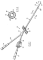
- Fig. 1 illustrates a catheter designated generally by the numeral 20 and useful for withdrawing blood through an intake 22 and returning treated blood through an outlet 24.
- the intake and outlet are connected by flexible tubes 26, 28 which can be clamped using conventional devices such as device 30 shown in tube 26.
- the tubes meet at a junction 32 at the proximal end of a main section 34 which terminates at its distal end in a transition portion 36 leading to a tip section 38. Blood is withdrawn through side openings 40 and returns through further side openings 42 and end opening 44.
- the main section 34 includes an outer tube 46 containing an inner tube 48.
- the openings 40 shown in Fig. 1, supply blood to an intake lumen 50 formed between the tubes 46, 48 and blood returns by a return lumen 52 contained within the inner tube 48.
- the junction 32 at the proximal end of the main section 34 connects the main portion to the tubes 26, 28 (as will be explained) and the catheter is completed by provision of a wing structure 54 used to attached the catheter in place in conventional fashion. It is preferable that the wing structure be rotatable on the catheter and provision is made for this with location provided by a sleeve 56 which prevents movement of the wing structure longitudinally relative to the catheter.
- the side openings 40 and 42 are typical of openings that can be provided around the periphery of the catheter to ensure flow into and out of the catheter from anywhere about the catheter. Consequently, if the catheter should be positioned against the wall of a vein, other openings will take over and provide the essential flow.
- Fig. 3 illustrates the details of the junction 32, and in particular the method of manufacturing this junction.
- the junction is prepared by first positioning a proximal end of the main section 34 in a mold (not shown) which is to create the junction 32 by injection molding using conventional techniques.
- the main section is positioned using first and second mandrels 74, 76.
- the mandrel 76 has a cylindrical portion 78 blending into a converging generally conical pattern 80, which in turn blends into a cylindrical end part 82 angled with respect to the portion 80.
- the part 82 fits closely inside a proximal end of the inner tube 48 and this tube is maintained in a position in engagement with the outer tube 46 by the mandrels 74, 76.
- the mandrel 74 has an outer cylindrical portion 84 which blends into a converging and generally conical portion 86 ending at a projection 88.
- This projection has a generally U-shaped configuration (as will be explained) and is angled with respect to the conical portion 86.
- the projection 88 on the end of the mandrel 74 is shaped to fit the space provided when the inner tube 48 is held against the inner surface of the outer tube 46. As a result it has a generally U-shaped configuration.
- the angular offsets of the projection 88 and the end part 82 of lumen 76 result in the projection and end part 82 extending in parallel axially with respect to the main section 34.
- the cylindrical portions 78 and 84 diverge sufficiently with respect to the axial main section that the ends of the respective intake and outlet tubes 26, 28 can be accommodated on the mandrels.
- the material is preferably polyurethane although other materials can be used provided that the usual requirements of compatibility, etc., are met.
- the mandrels are removed, and because there is some flexibility in the material, the mandrels can be pulled out without causing any damage.
- Fig. 3 The structure shown in Fig. 3 has particular significance in the resulting flow through the catheter. Unlike previous co-axial catheters, the flow tends to remain linear due to the fact that the intake and return tubes 26, 28 are generally in line with the main section 34. Previously, one of these tubes was in line and the other was connected through the side of the main section so that the flow must pass through a significant angle which in some instances approached 90 degrees. This is most undesirable because any changes in direction of this kind will result in turbulence in the blood flow with potential for damage to the blood. It is well established that pressure fluctuations in blood flow paths should be minimized, and this structure tends to limit such variations.
- the angle shown as "A" in Fig. 3 indicates the divergence between the tubes 26, 28 as they leave the junction 32. Because of the construction, it is possible to maintain this angle in the order of 15 to 20 degrees and is readily maintained below 30 degrees. As a result, the flow into and out of the catheter is essentially axial with reference to the main section 34 at all times. This is because the angle of the tubes 26, 28 with reference to the axis of the main section is half of the range up to 30 degrees.
Description
- This invention relates to dual lumen catheters for use in haemodialysis treatments and more particularly to the structure of the proximal end of a dual lumen catheter having co-axial intake and return lumens.
- Haemodialysis treatments have been developed since the early 1960s using a variety of combinations and arrangements of catheters. The earliest treatments were conducted using two needles in the same vein and this subsequently led to pioneer work done by Dr. Shaldon in England, who used two flexible catheters which could be left in place for limited periods. It was recognised by some practitioners that it would be preferable to use a single incision rather than to use two and this led to the development of techniques involving dual flow catheters. There are two basic types. The first to be attempted was a coaxial catheter with the intake lumen surrounding the return lumen. While this had advantages, there were some difficulties of manufacture. The other approach is to use side-by-side lumens either in individual tubes connected to one another or in a single tube divided by an interior septum so that the lumens are D-shaped. These structures also had advantages and disadvantages, the notable disadvantage being that, because the lumens are side-by-side, the intake openings must be in one side of the catheter. As a consequence of this, if the catheter were to attach itself to the wall of a vein due to suction applied to the intake lumen then, of course, the flow would stop. Medical staff then have to move the catheter by rotating it until blood again flows. This is a very delicate manipulation which is normally performed only by a qualified medical practitioner who must be available at all times in case the flow is discontinued.
- The side-by-side structures have advantages in manufacture due to the fact that the two lumens can be created simultaneously in an extrusion. This had led to great activity in developing devices having side-by-side D-shaped lumens at the expense of co-axial structures. Nevertheless, due to the inherent disadvantages of the side-by-side structures, there has been renewed interest in developing suitable co-axial devices. This is primarily because the intake lumen can have openings in any part of the wall of the catheter. As a result, no matter where the catheter may rest against a vein, some of the intake openings remain patent. There is then less likelihood that the procedure must be serviced by a trained medical practitioner. An example of a co-axial device is found in British Patent Specification GB-A-1284537.
- Catheters having side-by-side lumens can have intake tubes attached more or less in line with the lumens. By contrast, co-axial lumens have been used with the inner lumen connected to an axial tube and the outer tube to a fitting which projects transversely with respect to the axis of the catheter. It would be preferable to avoid this arrangement because it is inherent in such a structure that blood must pass along a path with a sudden change in direction and this can cause blood damage.
- It is an object of the present invention to provide a co-axial catheter having inlet and outlet tubes projecting from the proximal end of the catheter generally in line with the axis of the catheter.
- Accordingly, in one of its aspects, the invention provides a dual lumen co-axial catheter of the type having a main section extending axially and having proximal and distal ends and including an inner tube defining a return lumen, and an outer tube containing the inner tube and combining with the inner tube to define an annular intake lumen, the outer tube extending along a longitudinal axis and defining intake openings providing access into the intake lumen, intake and outlet tubes at the proximal end of the main section, and a junction coupling the tubes to the main section with the intake tube coupled for receiving blood from the intake lumen and the outlet tube coupled for delivering treated blood to the return lumen, the co-axial catheter being characterised by the inner and outer tubes being in contact inside the junction and the tubes leaving the junction to opposite sides of the axial direction with an angle of divergence of less than about 30 degrees.
- In accordance with another aspect of the invention, a method of coupling inner and outer lumens of a co-axial dual lumen catheter to intake and outlet tubes at a proximal end of the catheter, the inner lumen being an inner tube and the outer lumen being the space between the inner tube and an outer tube which contains the inner tube loosely, the method characterised by providing a first mandrel having a cylindrical end part proportioned to fit closely inside the inner tube, and a first cylindrical portion angled with respect to the end part at an angle of less than about 15 degrees providing a second mandrel having a projection shaped to fit between the inner tube and the outer tube with the tubes in contact with one another, and a second cylindrical portion angled with respect to the projection at an angle of less than about 15 degrees placing the mandrels with the end part and the projection extending in parallel with the inner tube engaged on the end part and the projection engaged between the inner and outer tubes; engaging one of the intake and outlet tubes on each of the first and second cylindrical portions; molding a junction to contain parts of the outer tube, and intake and outlet tubes and removing the mandrels through the intake and outlet tubes.
- These and other aspects of the invention will be better understood with reference to the drawings and the following description, in which:
- Fig. 1 is an isometric view of a catheter according to a preferred embodiment of the invention;
- Fig. 2 is a sectional view of Fig. 1 drawn to a larger scale; and
- Fig. 3 is a partially sectional view showing a junction at the proximal end of the catheter and demonstrating both the structure and a method of making the catheter with this junction.
- Reference is made firstly to Fig. 1 which illustrates a catheter designated generally by the
numeral 20 and useful for withdrawing blood through anintake 22 and returning treated blood through anoutlet 24. The intake and outlet are connected byflexible tubes device 30 shown intube 26. The tubes meet at ajunction 32 at the proximal end of amain section 34 which terminates at its distal end in atransition portion 36 leading to atip section 38. Blood is withdrawn throughside openings 40 and returns throughfurther side openings 42 and end opening 44. - As seen in Fig. 2, the
main section 34 includes anouter tube 46 containing aninner tube 48. Theopenings 40, shown in Fig. 1, supply blood to anintake lumen 50 formed between thetubes return lumen 52 contained within theinner tube 48. Thejunction 32 at the proximal end of themain section 34 connects the main portion to thetubes 26, 28 (as will be explained) and the catheter is completed by provision of awing structure 54 used to attached the catheter in place in conventional fashion. It is preferable that the wing structure be rotatable on the catheter and provision is made for this with location provided by asleeve 56 which prevents movement of the wing structure longitudinally relative to the catheter. - The
side openings - Reference is next made to Fig. 3 which illustrates the details of the
junction 32, and in particular the method of manufacturing this junction. As seen in Fig. 3, the junction is prepared by first positioning a proximal end of themain section 34 in a mold (not shown) which is to create thejunction 32 by injection molding using conventional techniques. The main section is positioned using first andsecond mandrels mandrel 76 has acylindrical portion 78 blending into a converging generallyconical pattern 80, which in turn blends into acylindrical end part 82 angled with respect to theportion 80. Thepart 82 fits closely inside a proximal end of theinner tube 48 and this tube is maintained in a position in engagement with theouter tube 46 by themandrels - The
mandrel 74 has an outercylindrical portion 84 which blends into a converging and generallyconical portion 86 ending at aprojection 88. This projection has a generally U-shaped configuration (as will be explained) and is angled with respect to theconical portion 86. - The
projection 88 on the end of themandrel 74 is shaped to fit the space provided when theinner tube 48 is held against the inner surface of theouter tube 46. As a result it has a generally U-shaped configuration. The angular offsets of theprojection 88 and theend part 82 oflumen 76 result in the projection andend part 82 extending in parallel axially with respect to themain section 34. Thecylindrical portions outlet tubes - Once the assembly shown in Fig. 3 has been completed, the mold is closed and injection takes place to form the
junction 32. The material is preferably polyurethane although other materials can be used provided that the usual requirements of compatibility, etc., are met. - The mandrels are removed, and because there is some flexibility in the material, the mandrels can be pulled out without causing any damage.
- The structure shown in Fig. 3 has particular significance in the resulting flow through the catheter. Unlike previous co-axial catheters, the flow tends to remain linear due to the fact that the intake and
return tubes main section 34. Previously, one of these tubes was in line and the other was connected through the side of the main section so that the flow must pass through a significant angle which in some instances approached 90 degrees. This is most undesirable because any changes in direction of this kind will result in turbulence in the blood flow with potential for damage to the blood. It is well established that pressure fluctuations in blood flow paths should be minimized, and this structure tends to limit such variations. - It is also significant that the resulting structure presents a smooth continuous internal surface to blood flow which again is desirable.
- The angle shown as "A" in Fig. 3 indicates the divergence between the
tubes junction 32. Because of the construction, it is possible to maintain this angle in the order of 15 to 20 degrees and is readily maintained below 30 degrees. As a result, the flow into and out of the catheter is essentially axial with reference to themain section 34 at all times. This is because the angle of thetubes - The embodiment described is representative of the invention and other embodiments and variations are within the scope of the invention as claimed.
Claims (4)
- A dual lumen co-axial catheter of the type having a main section (34) extending axially and having proximal and distal ends and including an inner tube (48) defining a return lumen (52), and an outer tube (46) containing the inner tube and combining with the inner tube to define an annular intake lumen (50), the outer tube extending along a longitudinal axis and defining intake openings (40) providing access into the intake lumen, intake and outlet tubes (22, 24) at the proximal end of the main section, and a junction (32) coupling the tubes to the main section with the intake tube coupled for receiving blood from the intake lumen and the outlet tube coupled for delivering treated blood to the return lumen, the co-axial catheter being characterised by the inner and outer tubes (48, 46) being in contact inside the junction and the tubes (22, 24) leaving the junction to opposite sides of the axial direction with an angle of divergence of less than about 30 degrees.
- A catheter as recited in claim 1 characterised in that the angle of divergence is about 15 to 20 degrees.
- A catheter as recited in claims 1 or 2 characterised in that the inner tube, outer tube and tip section are round in cross-section.
- A method of coupling inner and outer lumens (52, 50) of a co-axial dual lumen catheter (20) to intake and outlet tubes (22, 24) at a proximal end of the catheter, the inner lumen being an inner tube (48) and the outer lumen being the space between the inner tube and an outer tube (46) which contains the inner tube loosely, the method characterised by providing a first mandrel (76) having a cylindrical end part (82) proportioned to fit closely inside the inner tube, and a first cylindrical portion (78) angled with respect to the end part at an angle of less than about 15 degrees providing a second mandrel (74) having a projection (88) shaped to fit between the inner tube and the outer tube with the tubes in contact with one another, and a second cylindrical portion (84) angled with respect to the projection at an angle of less than about 15 degrees placing the mandrels with the end part (82) and the projection (88) extending in parallel with the inner tube (48) engaged on the end part (82) and the projection (88) engaged between the inner and outer tubes (48, 46); engaging one of the intake and outlet tubes (22, 24) on each of the first and second cylindrical portions (78, 84); molding a junction to contain parts of the outer tube, and intake and outlet tubes; and removing the mandrels through the intake and outlet tubes.
Applications Claiming Priority (2)
| Application Number | Priority Date | Filing Date | Title |
|---|---|---|---|
| CA 2061163 CA2061163C (en) | 1992-02-13 | 1992-02-13 | Co-axial catheter |
| CA2061163 | 1992-02-13 |
Publications (3)
| Publication Number | Publication Date |
|---|---|
| EP0555582A2 EP0555582A2 (en) | 1993-08-18 |
| EP0555582A3 EP0555582A3 (en) | 1993-10-20 |
| EP0555582B1 true EP0555582B1 (en) | 1997-06-04 |
Family
ID=4149249
Family Applications (1)
| Application Number | Title | Priority Date | Filing Date |
|---|---|---|---|
| EP19920308786 Expired - Lifetime EP0555582B1 (en) | 1992-02-13 | 1992-09-25 | Co-axial catheter |
Country Status (4)
| Country | Link |
|---|---|
| EP (1) | EP0555582B1 (en) |
| CA (1) | CA2061163C (en) |
| DE (1) | DE69220205T2 (en) |
| HK (1) | HK1007514A1 (en) |
Families Citing this family (2)
| Publication number | Priority date | Publication date | Assignee | Title |
|---|---|---|---|---|
| ATE479462T1 (en) † | 1993-12-03 | 2010-09-15 | Edwards Lifesciences Ag | CARDIOPULMONARY BYPASS FOR CLOSED THORAX PROCEDURES |
| IL119835A0 (en) * | 1996-09-12 | 1997-03-18 | Rid Riskin Devices Ltd | Medical apparatus and method for treating diseases in humans and animals |
Family Cites Families (2)
| Publication number | Priority date | Publication date | Assignee | Title |
|---|---|---|---|---|
| GB1284537A (en) * | 1968-09-19 | 1972-08-09 | Alan Edward Curtis Bennett | An improved transfusion device |
| US4895561A (en) * | 1988-05-16 | 1990-01-23 | Mahurkar Sakharam D | Dual-lumen catheter-connecting system |
-
1992
- 1992-02-13 CA CA 2061163 patent/CA2061163C/en not_active Expired - Lifetime
- 1992-09-25 DE DE1992620205 patent/DE69220205T2/en not_active Expired - Fee Related
- 1992-09-25 EP EP19920308786 patent/EP0555582B1/en not_active Expired - Lifetime
-
1998
- 1998-06-25 HK HK98106655A patent/HK1007514A1/en not_active IP Right Cessation
Also Published As
| Publication number | Publication date |
|---|---|
| HK1007514A1 (en) | 1999-04-16 |
| EP0555582A3 (en) | 1993-10-20 |
| CA2061163C (en) | 2003-12-09 |
| DE69220205T2 (en) | 1997-11-13 |
| DE69220205D1 (en) | 1997-07-10 |
| CA2061163A1 (en) | 1993-08-14 |
| EP0555582A2 (en) | 1993-08-18 |
Similar Documents
| Publication | Publication Date | Title |
|---|---|---|
| USRE41462E1 (en) | Bent co-axial catheter | |
| US5976103A (en) | Dual lumen coaxial catheter | |
| US5480380A (en) | Coaxial dual lumen catheter | |
| CA2168009C (en) | Triple lumen catheter | |
| US5897497A (en) | Guiding catheter introducer assembly | |
| US4406656A (en) | Venous catheter having collapsible multi-lumens | |
| US5167623A (en) | Multilumen catheter | |
| US5795326A (en) | Double lumen tubing design for catheter | |
| EP1421967B1 (en) | Blood treatment catheter assembly | |
| US7749185B2 (en) | Method of inserting double-Y-shaped catheter with attachable hubs | |
| US4931049A (en) | Catheter coupling system | |
| EP0322225A3 (en) | Triple lumen catheter | |
| US20170239442A1 (en) | Catheter | |
| EP0555582B1 (en) | Co-axial catheter | |
| JPH05329216A (en) | Catheter tube | |
| CA1202340A (en) | Swivel coupling | |
| US20230256209A1 (en) | Central Catheters, Assemblies, and Methods Thereof | |
| CA2329742A1 (en) | Stylet for controlled deformation of a tube |
Legal Events
| Date | Code | Title | Description |
|---|---|---|---|
| PUAI | Public reference made under article 153(3) epc to a published international application that has entered the european phase |
Free format text: ORIGINAL CODE: 0009012 |
|
| AK | Designated contracting states |
Kind code of ref document: A2 Designated state(s): AT BE CH DE DK ES FR GB GR IE IT LI LU MC NL PT SE |
|
| PUAL | Search report despatched |
Free format text: ORIGINAL CODE: 0009013 |
|
| AK | Designated contracting states |
Kind code of ref document: A3 Designated state(s): AT BE CH DE DK ES FR GB GR IE IT LI LU MC NL PT SE |
|
| RBV | Designated contracting states (corrected) |
Designated state(s): BE DE ES FR GB NL SE |
|
| 17P | Request for examination filed |
Effective date: 19940214 |
|
| 17Q | First examination report despatched |
Effective date: 19960207 |
|
| GRAG | Despatch of communication of intention to grant |
Free format text: ORIGINAL CODE: EPIDOS AGRA |
|
| RAP1 | Party data changed (applicant data changed or rights of an application transferred) |
Owner name: MED-PRO DESIGN, INC. |
|
| RBV | Designated contracting states (corrected) |
Designated state(s): BE DE ES FR GB IT NL SE |
|
| GRAH | Despatch of communication of intention to grant a patent |
Free format text: ORIGINAL CODE: EPIDOS IGRA |
|
| GRAH | Despatch of communication of intention to grant a patent |
Free format text: ORIGINAL CODE: EPIDOS IGRA |
|
| GRAA | (expected) grant |
Free format text: ORIGINAL CODE: 0009210 |
|
| AK | Designated contracting states |
Kind code of ref document: B1 Designated state(s): BE DE ES FR GB IT NL SE |
|
| PG25 | Lapsed in a contracting state [announced via postgrant information from national office to epo] |
Ref country code: ES Free format text: THE PATENT HAS BEEN ANNULLED BY A DECISION OF A NATIONAL AUTHORITY Effective date: 19970604 |
|
| REF | Corresponds to: |
Ref document number: 69220205 Country of ref document: DE Date of ref document: 19970710 |
|
| ET | Fr: translation filed | ||
| PG25 | Lapsed in a contracting state [announced via postgrant information from national office to epo] |
Ref country code: SE Effective date: 19970904 |
|
| PGFP | Annual fee paid to national office [announced via postgrant information from national office to epo] |
Ref country code: SE Payment date: 19970918 Year of fee payment: 6 |
|
| PLBE | No opposition filed within time limit |
Free format text: ORIGINAL CODE: 0009261 |
|
| STAA | Information on the status of an ep patent application or granted ep patent |
Free format text: STATUS: NO OPPOSITION FILED WITHIN TIME LIMIT |
|
| 26N | No opposition filed | ||
| REG | Reference to a national code |
Ref country code: GB Ref legal event code: 732E |
|
| REG | Reference to a national code |
Ref country code: GB Ref legal event code: IF02 |
|
| REG | Reference to a national code |
Ref country code: FR Ref legal event code: TP Ref country code: FR Ref legal event code: CA |
|
| PGFP | Annual fee paid to national office [announced via postgrant information from national office to epo] |
Ref country code: NL Payment date: 20080903 Year of fee payment: 17 Ref country code: IT Payment date: 20080926 Year of fee payment: 17 Ref country code: FR Payment date: 20080915 Year of fee payment: 17 |
|
| PGFP | Annual fee paid to national office [announced via postgrant information from national office to epo] |
Ref country code: DE Payment date: 20081002 Year of fee payment: 17 |
|
| PGFP | Annual fee paid to national office [announced via postgrant information from national office to epo] |
Ref country code: BE Payment date: 20080922 Year of fee payment: 17 |
|
| PGFP | Annual fee paid to national office [announced via postgrant information from national office to epo] |
Ref country code: GB Payment date: 20081001 Year of fee payment: 17 |
|
| BERE | Be: lapsed |
Owner name: *MED-PRO DESIGN INC. Effective date: 20090930 |
|
| REG | Reference to a national code |
Ref country code: NL Ref legal event code: V1 Effective date: 20100401 |
|
| GBPC | Gb: european patent ceased through non-payment of renewal fee |
Effective date: 20090925 |
|
| REG | Reference to a national code |
Ref country code: FR Ref legal event code: ST Effective date: 20100531 |
|
| PG25 | Lapsed in a contracting state [announced via postgrant information from national office to epo] |
Ref country code: NL Free format text: LAPSE BECAUSE OF NON-PAYMENT OF DUE FEES Effective date: 20100401 Ref country code: FR Free format text: LAPSE BECAUSE OF NON-PAYMENT OF DUE FEES Effective date: 20090930 Ref country code: DE Free format text: LAPSE BECAUSE OF NON-PAYMENT OF DUE FEES Effective date: 20100401 |
|
| PG25 | Lapsed in a contracting state [announced via postgrant information from national office to epo] |
Ref country code: BE Free format text: LAPSE BECAUSE OF NON-PAYMENT OF DUE FEES Effective date: 20090930 |
|
| PG25 | Lapsed in a contracting state [announced via postgrant information from national office to epo] |
Ref country code: GB Free format text: LAPSE BECAUSE OF NON-PAYMENT OF DUE FEES Effective date: 20090925 |
|
| PG25 | Lapsed in a contracting state [announced via postgrant information from national office to epo] |
Ref country code: IT Free format text: LAPSE BECAUSE OF NON-PAYMENT OF DUE FEES Effective date: 20090925 |