EP0554221A1 - Apparatus for controlling fluid injection pressure of an auxiliary nozzle in a jet loom - Google Patents
Apparatus for controlling fluid injection pressure of an auxiliary nozzle in a jet loom Download PDFInfo
- Publication number
- EP0554221A1 EP0554221A1 EP93810047A EP93810047A EP0554221A1 EP 0554221 A1 EP0554221 A1 EP 0554221A1 EP 93810047 A EP93810047 A EP 93810047A EP 93810047 A EP93810047 A EP 93810047A EP 0554221 A1 EP0554221 A1 EP 0554221A1
- Authority
- EP
- European Patent Office
- Prior art keywords
- weft
- auxiliary
- fluid
- loom
- auxiliary nozzles
- Prior art date
- Legal status (The legal status is an assumption and is not a legal conclusion. Google has not performed a legal analysis and makes no representation as to the accuracy of the status listed.)
- Granted
Links
Images

Classifications
-
- D—TEXTILES; PAPER
- D03—WEAVING
- D03D—WOVEN FABRICS; METHODS OF WEAVING; LOOMS
- D03D47/00—Looms in which bulk supply of weft does not pass through shed, e.g. shuttleless looms, gripper shuttle looms, dummy shuttle looms
- D03D47/28—Looms in which bulk supply of weft does not pass through shed, e.g. shuttleless looms, gripper shuttle looms, dummy shuttle looms wherein the weft itself is projected into the shed
- D03D47/30—Looms in which bulk supply of weft does not pass through shed, e.g. shuttleless looms, gripper shuttle looms, dummy shuttle looms wherein the weft itself is projected into the shed by gas jet
- D03D47/3066—Control or handling of the weft at or after arrival
- D03D47/3073—Detection means therefor
-
- D—TEXTILES; PAPER
- D03—WEAVING
- D03D—WOVEN FABRICS; METHODS OF WEAVING; LOOMS
- D03D47/00—Looms in which bulk supply of weft does not pass through shed, e.g. shuttleless looms, gripper shuttle looms, dummy shuttle looms
- D03D47/28—Looms in which bulk supply of weft does not pass through shed, e.g. shuttleless looms, gripper shuttle looms, dummy shuttle looms wherein the weft itself is projected into the shed
- D03D47/30—Looms in which bulk supply of weft does not pass through shed, e.g. shuttleless looms, gripper shuttle looms, dummy shuttle looms wherein the weft itself is projected into the shed by gas jet
- D03D47/3026—Air supply systems
- D03D47/3033—Controlling the air supply
- D03D47/304—Controlling of the air supply to the auxiliary nozzles
-
- D—TEXTILES; PAPER
- D03—WEAVING
- D03D—WOVEN FABRICS; METHODS OF WEAVING; LOOMS
- D03D47/00—Looms in which bulk supply of weft does not pass through shed, e.g. shuttleless looms, gripper shuttle looms, dummy shuttle looms
- D03D47/28—Looms in which bulk supply of weft does not pass through shed, e.g. shuttleless looms, gripper shuttle looms, dummy shuttle looms wherein the weft itself is projected into the shed
- D03D47/30—Looms in which bulk supply of weft does not pass through shed, e.g. shuttleless looms, gripper shuttle looms, dummy shuttle looms wherein the weft itself is projected into the shed by gas jet
- D03D47/3026—Air supply systems
- D03D47/3053—Arrangements or lay out of air supply systems
Abstract
Description
- The present invention relates to an apparatus for controlling fluid injection pressure of an auxiliary nozzle in a jet loom and, more specifically, to the above apparatus in a jet loom, having at least one weft detector, a plurality of the auxiliary nozzles, a fluid supply reservoir from which fluid under pressure is supplied to the auxiliary nozzles through lines each having an electromagnetically-operated valve, and a controller for controlling the operation of the valve.
- In a conventional jet loom having a weft feeler which is disposed at a predetermined terminating extremity position of weft flying passage across the loom for monitoring the weft arrival time, or the time at which the leading end of an inserted weft arrives at a position defined by the weft feeler, the fluid pressure in a fluid supply reservoir is so set that a specific kind of weft, which requires the longest time to fly to the weft feeler, may arrive at the destination within a predetermined period time, and the time at which a solenoid-operated stop pin in a drum type weft measuring device is disengaged from the drum thereof for weft releasing, as well as the times at which main and auxiliary nozzles are activated respectively for fluid injection are controlled according the average arrival time of the leading end of the inserted wefts.
- This method of controlling the fluid injection pressure of auxiliary nozzles tends to waste fluid and it is practically impossible with this method to recover the flying speed of such weft that has once decelerated or stalled on its way of flying through a warp shed. An attempt to solve the above problems has been made by an apparatus disclosed by Publication of unexamined Japanese patent application No. 62-257441 (1987). This apparatus includes three separate reservoirs holding therein fluids under different pressures and the reservoir from which its fluid is to be supplied to the respective auxiliary nozzles is selectively changed as required in accordance with a signal transmitted from a weft detector so that the weft speed is adjusted on its way of flying through a shed. This conventional apparatus is disadvantageous, however, in that the provision of plural fluid supply reservoirs and their associated conduit lines require additional space for their installation and make the whole apparatus complicated.
- Therefore, it is an object of the present invention to provide an auxiliary nozzle injection pressure controlling apparatus in a jet loom which can solve the above-identified problems by saving the installation space, as well as fluid consumption of the auxiliary nozzles.
- In order to solve the above problems, there is provided an apparatus for controlling the fluid injection pressure of an auxiliary nozzle in a jet loom, having at least one weft detector, a plurality of the auxiliary nozzles, a fluid supply reservoir from which fluid under pressure is supplied to the auxiliary nozzles through lines each having a first electromagnetically-operated valve, and a controller for controlling the operation of the valves, the apparatus being characterized in that in that each of the lines is provided with a bypass line having a second electromagnetically-operated valve whose operation may be controlled by the controller for each weft insertion according to the information of time at which each inserted weft has arrived at a predetermined position along weft flying passage in a warp shed of the loom.
- In the above apparatus having a line which bypasses the main line connected between the fluid supply reservoir and the auxiliary nozzles and has therein a valve whose operation is controlled by the controller according to the information of weft arrival times from the weft detectors, the valve in the bypass line is caused to open thereby to activate its associated auxiliary nozzle in response to a Signal from any weft detector then detecting a delay in the weft arrival time at a position upstream of the above auxiliary nozzle. Consequently, air under pressure through the bypass line, as well as air through the main line, is supplied to the auxiliary nozzle, with the result that the weft is accelerated so that it can arrive in a predetermined time at a weft feeler disposed at a terminating extremity position of weft flying passage across the loom. Because the apparatus of the invention requires only a single fluid supply reservoir, space for installation of the reservoir can be saved and the apparatus itself constructed simple. Additionally, each main line may be provided with a plurality of bypass lines through which air streams of different flow rates are flown for effecting two-step acceleration. Alternatively, in such arrangement of plural bypass lines, air through one bypass line is used for the acceleration, while the other bypass line may be arranged so as to supply air under a lower pressure and used in conjunction with the main line for inserting different kinds of weft alternately.
- The following will describe an embodiment of the apparatus for controlling the fluid injection pressure of an auxiliary nozzle in a jet loom, while having reference to the accompanying drawings. Figs. 1 through 4 show embodiments of the present invention and details thereof:
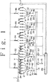
- FIG. 1
- is an illustrative schematic view showing an embodiment of an apparatus for controlling fluid injection pressure of an auxiliary nozzle in a jet loom according to the present invention;
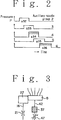
- FIG. 2
- is a diagram showing air injection timing of the auxiliary nozzles of the respective groups;
- FIG. 3
- is an enlarged schematic view showing another embodiment of the apparatus according to the invention; and
- FIG. 4
- is an enlarged schematic view showing still another embodiment of the apparatus according to the invention.
- Referring to FIG. 1, there is shown a main nozzle 1 of the loom for inserting a weft Y into a warp shed by an air jet issued therefrom. The inserted weft Y is assisted in flying through the shed by air jets injected from groups of auxiliary nozzles 2-6 to accelerate the weft so that the leading end thereof reaches a weft feeler 7 which is located at a predetermined terminating extremity position of weft flying passage beyond the shed across the loom for monitoring the time at which the leading end arrives at that position defined by the weft feeler. Each of the auxiliary nozzle groups 2-6 comprises five
nozzles 2a, 2b, 2c, 2d, 2e; 3a-3e; 4a-4e; 5a-5e. Five auxiliary nozzles of each group are connected to acommon air distributor - There is provided an elongated
hollow air reservoir 13 located across the loom and holding therein compressed air. Theair reservoir 13 has an inlet connected to anysuitable air source 15 through aregulator 14 for adjusting the air pressure in the reservoir and outlets connected to the distributors 8-12 of the respective groups of auxiliary nozzles 2-6 through conduit lines 16-20 having fixed throttle valves 21-25 for restricting the flow of air therethrough to the auxiliary nozzles so as to adjust the air injection pressure of the nozzles with respect the air pressure in thereservoir 13. The lines 16-20 include solenoid-operated valves 27-31 and the time at which the solenoids are energized to open their associated valves of each group is controlled by acontroller 26. - The apparatus includes five weft detectors 32-36 disposed in a warp shed for detecting the time at which the leading end of an inserted weft just arrives at each of such weft detectors and connected to the
controller 26 for transmitting thereto signals which are representative of the arrival times of the leading end at the respective weft detectors. As shown in FIG. 1, thecontroller 26 is connected also to the weft feeler 7 for receiving therefrom a signal representative of the time at which the leading end of an inserted weft arrives at that weft feeler. Thecontroller 26 is adapted to receive other signals indicative of other information necessary for controlling weft insertion, e.g. air pressure in thereservoir 13 which is detected by apressure sensor 37 connected to the reservoir. - The apparatus according to the invention further includes bypass lines 42-46 connected to bypass the throttle valves 21-25 and the solenoid-operated valves 27-31 in the main lines 16-20. The bypass lines 42-46 have second solenoid-operated valves 3741 whose operation is controlled by the
controller 26. Unlike the main lines 16-20, the bypass lines 42-46 have no throttle, thus allowing more air to flow therethrough than through the main lines to the distributors 8-12. In other words, flowing air through the bypass lines 42-46 produces air jets under a higher pressure from the auxiliary nozzles than flowing air through the main lines 16-20 having the air flow restricting throttles 21-25, thus making possible acceleration of a weft flying in a shed. - In operation, when the
weft detector controller 26 then responding to a signal from that weft detector commands the solenoid for thevalve 39 to be energized so that the valve in thebypass line 44 for the group ofauxiliary nozzles 4a, 4b, 4c, 4d, 4e is opened. Accordingly, air under the same pressure as the air in thereservoir 13 is allowed through thebypass line 44 and meets at thedistributor 29 with air flown through themain line 18 to be supplied together therewith to theauxiliary nozzles 4a, 4b, 4c, 4d, 4e. Thus, air under a pressure which is higher than that of air flowing only through thevalve 29 in the main line IS can be injected from theauxiliary nozzles 4, as indicated by the timing diagram shown in FIG. 2, thereby accelerating the flying speed of the inserted weft so as to recover the delay. If theweft detector detecting point controller 26 causes the solenoid-operated valve 41 in thebypass line 46 to for the group ofauxiliary nozzles 6 to be opened. Accordingly, two air flows through the main andbypass lines distributor 12, from where the combined air flow is supplied to theauxiliary nozzles 6a, 6b, 6c, 6d, 6e of thegroup 6. Thus, air under a higher pressure can be injected from the auxiliary nozzles and the flying speed of the inserted weft can be accelerated by air jets from theauxiliary nozzle group 5, as indicated in the diagram of FIG. 2. - Thus, in the event that the flying speed of an inserted weft is slowed down on its way through a shed, any appropriate valve of the solenoid-operated valves 37-41 in the bypass lines 42-46 is caused to open so that air flowing through the bypass line meets at the distributor with air flowing through the main line, thereby increasing air injection pressure of the auxiliary nozzles of a group located just downstream of the position where the slowdown of weft flying speed has been detected. The result is that the weft flying speed is accelerated by such increased air injection pressure of the auxiliary nozzles. Alternatively, an increase of the air injection pressure of the auxiliary nozzles for the acceleration may be effected by allowing air to flow only through the bypass line with the main lines closed.
- A modified embodiment of the invention is illustrated in FIG. 3, wherein the bypass line, e.g. 42, has an
adjustable throttle valve 47 to make possible adjustment of the acceleration which may be required when any different kind of weft is to be handled. - FIG. 4 shows a further modified embodiment of the invention which differs from that shown in FIG. 3 in that a
second bypass line 48 is added. In this embodiment, at least one of thebypass lines adjustable throttle valve throttle valve 21 in themain line 16. By so arranging, the bypass line having the adjustable throttle valve may be used for decelerating the weft flying speed with the solenoid-operatedvalve 27 in themain line 16 then closed. The other bypass line is used for the acceleration as described in the above. Alternatively, in the arrangement of FIG. 4, thethrottle valve 50 may have very little restriction of air flow while thethrottle valve 47 slight restriction so that two-step acceleration can be effected by firstly opening thevalve 37 and then activating thevalve 49 with theformer valve 37 closed. It would be understood readily by those skilled in the art that this embodiment of FIG. 4 is applicable to alternate insertion of two different kinds of weft. That is, air through thebypass line 48 is used for the acceleration and thevalves - As it is apparent from the foregoing description of the embodiments according to the invention, provision of a line bypassing the main line between the air supply reservoir and the air distributor and having therein a controlled valve can dispense with a plurality of air reservoirs holding air under different pressures. Therefore, the construction of the apparatus can be simplified and requires smaller space for the installation. Additionally, the apparatus of the invention is applicable to insertion of different kinds of weft.
- It is to be understood by those skilled in the art that the present invention is not limited to the above-described embodiments but it may be practiced in other various changes and modifications. For example, the weft detectors 32-36 provided in a warp shed may be substituted for other means adapted to detect the leading end of an inserted weft, e.g. a combination of a balloon sensor which is located adjacent a drum type weft measuring device disposed upstream of the main weft inserting nozzle for detecting the balloon in weft releasing from the device and a device which is adapted to figure out the current position of the inserted weft leading end on the basis of weft release signals provided by the balloon sensor.
- To provide an apparatus for controlling fluid injection pressure of an
auxiliary nozzle 2a-2e, 3a-3e, 4a-4e. 5a-5e, 6a-6e in a jet loom, which is simple in construction requiring only a small space for installation and saves fluid consumption. The apparatus is adapted for use in a jet loom and has at least one weft detector 32-36, a plurality ofauxiliary nozzles 2a-2e, 3a-3e, 4a-4e. 5a-5e, 6a-6e, afluid supply reservoir 13 from which fluid under pressure is supplied to each of theauxiliary nozzles 2a-2e, 3a-3e, 4a-4e. 5a-5e, 6a-6e through conduit lines 16-20 each having a first electromagnetically-operated valves 27-31, and acontroller 26 for controlling the operation of the valves 27-31, wherein the apparatus includes a second electromagnetically-operated valve 37-41 provided in a bypass line 42-46 bypassing the main line and the operation of the second valve 37-41 is controlled by thecontroller 26 according to the information of time at which the leading end of each inserted weft Y has arrived at a predetermined position along weft flying passage in a warp shed of the loom. -
- Apparatus for controlling fluid injection pressure of an auxiliary nozzle in a jet loom according to the invention can be constructed simple and is advantageous in space factor by provision of a line bypassing the main line connected between the air supply reservoir and an auxiliary nozzle, and having therein an electromagnetically-controlled valve whose operation may be controlled by a controller for each weft insertion.
- 1 .... Main nozzle,
2, 3, 4, 5, 6 .... Auxiliary nozzle groups,
7 .... Weft feeler,
8, 9, 10, 11, 12 .... Air distributors,
13 .... Air supply reservoir,
14 .... Air regulator,
15 .... Air source,
16, 17, 18, 19, 20 .... Main lines,
21, 22, 23, 24, 25.... Throttle valves,
26 .... Controller,
27, 28, 29, 30, 31... Solenoid-operated valves,
32, 33, 34, 35, 36... Weft detectors,
37, 38, 39, 40, 41..... Solenoid-operated valves
42, 43, 44, 45, 46... Bypass lines,
47, 50 .... Adjustable throttle valves,
48 .... Second bypass line,
49 .... Solenoid-operated valve.
Claims (9)
- An apparatus for controlling the fluid injection pressure of an auxiliary nozzle (2a-2e, 3a-3e, 4a-4e. 5a-5e, 6a-6e) in a jet loom, comprising at least one weft detector (32, 33, 34, 35, 36), a plurality of the auxiliary nozzles (2a-2e, 3a-3e, 4a-4e. 5a-5e, 6a-6e), a fluid supply reservoir (13) from which fluid under pressure is supplied to said auxiliary nozzles (2a-2e, 3a-3e, 4a-4e. 5a-5e, 6a-6e) through lines (16, 17, 18, 19, 20) each having a first electromagnetically-operated valve (27, 28, 29, 30, 31), and a controller (26) for controlling the operation of said valves (27, 28, 29, 30, 31), said apparatus being characterized in that each of said lines (16, 17, 18, 19, 20) is provided with a bypass line (42, 43, 44, 45, 46) having a second electromagnetically-operated valve (37, 38, 39, 40, 41) whose operation may be controlled by said controller (26) for each weft insertion according to the information of time at which each inserted weft (Y) has arrived at a predetermined position along weft flying passage in a warp shed of the loom.
- An apparatus for controlling the fluid injection pressure of an auxiliary nozzle (2a-2e, 3a-3e, 4a-4e. 5a-5e, 6a-6e) in a jet loom, comprising at least one weft detector (32, 33, 34, 35, 36) which is placed along the weft flying passage in a warp shed of the loom, a plurality of auxiliary nozzles (2a-2e, 3a-3e, 4a-4e. 5a-5e, 6a-6e), a fluid supply reservoir (13) from which fluid under pressure is supplied to said auxiliary nozzles (2a-2e, 3a-3e, 4a-4e. 5a-5e, 6a-6e) through lines (16, 17, 18, 19, 20) each having a first electromagnetically-operated valve (27, 28, 29, 30, 31), and a controller (26) for controlling the operation of said valves (27, 28, 29, 30, 31), said apparatus being characterized in that at least one of said lines (16, 17, 18, 19, 20) is provided with a bypass line (42, 43, 44, 45, 46) leading to at least one auxiliary nozzle (2a-2e, 3a-3e, 4a-4e. 5a-5e, 6a-6e ) and having a second electromagnetically-operated valve (37, 38, 39, 40, 41) whose operation is controlled by said controller (26) for each weft insertion according to the information of time at which each inserted weft (Y) has arrived at a predetermined position of a weft detector (32, 33, 34, 35, 36) which is placed along the weft flying passage in the warp shed of the loom.
- An apparatus as claimed in claim 1 or 2, with a plurality of weft detectors (32-36) being places along the weft flying passage in the warp shed of the loom and/or a plurality of bypasses (42-46) connecting the fluid reservoir (13) with individual auxiliary nozzles (2a-2e, 3a-3e, 4a-4e. 5a-5e, 6a-6e) or groups of auxiliary nozzles (2a-2e, 3a-3e, 4a-4e. 5a-5e, 6a-6e).
- An apparatus as claimed in any of claims 1 to 3, with a plurality of bypasses (42-46) connected to one auxiliary nozzle (2a-2e, 3a-3e, 4a-4e. 5a-5e, 6a-6e) or a group of auxiliary nozzles (2a-2e, 3a-3e, 4a-4e. 5a-5e, 6a-6e).
- An apparatus as claimed in any of claims 1 to 4, where each bypass (42-46) is bypassing at least one throttle valve (21-25) of a fluid conduit line (16-20).
- An apparatus as claimed in any of claims 1 to 5, where fluid conduit lines (16-20) and bypasses (42-46), as well as a group of auxiliary nozzles are connected to at least one fluid distributor (8-12)
- Apparatus as claimed in any of claim 1 to 6, for an air jet loom with auxiliary air jet nozzles.
- Fluid jet loom with an apparatus as claimed in any of claims 1 to 7.
- Air jet loom with an apparatus as claimed in any of claims 1 to 7.
Applications Claiming Priority (2)
| Application Number | Priority Date | Filing Date | Title |
|---|---|---|---|
| JP11982/92 | 1992-01-27 | ||
| JP1198292A JPH05230739A (en) | 1992-01-27 | 1992-01-27 | Control device for jetting pressure of subnozzle in jet loom |
Publications (2)
| Publication Number | Publication Date |
|---|---|
| EP0554221A1 true EP0554221A1 (en) | 1993-08-04 |
| EP0554221B1 EP0554221B1 (en) | 1997-06-11 |
Family
ID=11792809
Family Applications (1)
| Application Number | Title | Priority Date | Filing Date |
|---|---|---|---|
| EP19930810047 Expired - Lifetime EP0554221B1 (en) | 1992-01-27 | 1993-01-26 | Apparatus for controlling fluid injection pressure of an auxiliary nozzle in a jet loom |
Country Status (3)
| Country | Link |
|---|---|
| EP (1) | EP0554221B1 (en) |
| JP (1) | JPH05230739A (en) |
| DE (1) | DE69311386T2 (en) |
Cited By (5)
| Publication number | Priority date | Publication date | Assignee | Title |
|---|---|---|---|---|
| EP0786546A1 (en) * | 1996-01-25 | 1997-07-30 | Lindauer Dornier Gesellschaft M.B.H | Process to control the operation of electrically controlled magnetic valves in looms |
| EP0790340A1 (en) * | 1996-02-14 | 1997-08-20 | Tsudakoma Kogyo Kabushiki Kaisha | Weft insertion control method |
| US6176272B1 (en) | 1998-06-02 | 2001-01-23 | Lindauer Dornier Gesellschaft Mbh | Method for monitoring the operation of an electromagnet in a weft prewinder of a weaving loom |
| KR100414959B1 (en) * | 2000-10-02 | 2004-01-13 | 가부시키가이샤 도요다 지도숏키 | Device for supplying compressed air in air-jet weaving machine |
| CN103114369A (en) * | 2013-01-29 | 2013-05-22 | 青岛铠硕纺机有限公司 | Independent air feed electronic wefting insertion system used for air-jet loom |
Families Citing this family (1)
| Publication number | Priority date | Publication date | Assignee | Title |
|---|---|---|---|---|
| JP5493639B2 (en) * | 2009-09-23 | 2014-05-14 | 株式会社豊田自動織機 | Weft insertion device in air jet loom |
Citations (4)
| Publication number | Priority date | Publication date | Assignee | Title |
|---|---|---|---|---|
| GB2085933A (en) * | 1980-10-22 | 1982-05-06 | Rueti Ag Maschf | A pneumatic thread-inserting system |
| EP0238128A2 (en) * | 1986-03-20 | 1987-09-23 | Picanol N.V. | Method for the control of auxiliary blowers for the insertion of a weft thread on weaving looms and device applied to this end |
| JPS62257441A (en) * | 1986-05-01 | 1987-11-10 | 株式会社豊田自動織機製作所 | Wefting method in jet loom |
| EP0465928A1 (en) * | 1990-06-27 | 1992-01-15 | VAMATEX S.p.A. | System to control the feeding of nozzles conveying the weft along the shed of fluid jet looms |
-
1992
- 1992-01-27 JP JP1198292A patent/JPH05230739A/en active Pending
-
1993
- 1993-01-26 EP EP19930810047 patent/EP0554221B1/en not_active Expired - Lifetime
- 1993-01-26 DE DE1993611386 patent/DE69311386T2/en not_active Expired - Fee Related
Patent Citations (4)
| Publication number | Priority date | Publication date | Assignee | Title |
|---|---|---|---|---|
| GB2085933A (en) * | 1980-10-22 | 1982-05-06 | Rueti Ag Maschf | A pneumatic thread-inserting system |
| EP0238128A2 (en) * | 1986-03-20 | 1987-09-23 | Picanol N.V. | Method for the control of auxiliary blowers for the insertion of a weft thread on weaving looms and device applied to this end |
| JPS62257441A (en) * | 1986-05-01 | 1987-11-10 | 株式会社豊田自動織機製作所 | Wefting method in jet loom |
| EP0465928A1 (en) * | 1990-06-27 | 1992-01-15 | VAMATEX S.p.A. | System to control the feeding of nozzles conveying the weft along the shed of fluid jet looms |
Cited By (7)
| Publication number | Priority date | Publication date | Assignee | Title |
|---|---|---|---|---|
| EP0786546A1 (en) * | 1996-01-25 | 1997-07-30 | Lindauer Dornier Gesellschaft M.B.H | Process to control the operation of electrically controlled magnetic valves in looms |
| US5787937A (en) * | 1996-01-25 | 1998-08-04 | Lindauer Dornier Gesellschaft Mbh | Method for monitoring the proper functioning of electromagnetic air valves in pneumatic looms |
| EP0790340A1 (en) * | 1996-02-14 | 1997-08-20 | Tsudakoma Kogyo Kabushiki Kaisha | Weft insertion control method |
| US5816295A (en) * | 1996-02-14 | 1998-10-06 | Tsudakoma Kogyo Kabushiki Kaisha | Weft insertion control method |
| US6176272B1 (en) | 1998-06-02 | 2001-01-23 | Lindauer Dornier Gesellschaft Mbh | Method for monitoring the operation of an electromagnet in a weft prewinder of a weaving loom |
| KR100414959B1 (en) * | 2000-10-02 | 2004-01-13 | 가부시키가이샤 도요다 지도숏키 | Device for supplying compressed air in air-jet weaving machine |
| CN103114369A (en) * | 2013-01-29 | 2013-05-22 | 青岛铠硕纺机有限公司 | Independent air feed electronic wefting insertion system used for air-jet loom |
Also Published As
| Publication number | Publication date |
|---|---|
| JPH05230739A (en) | 1993-09-07 |
| EP0554221B1 (en) | 1997-06-11 |
| DE69311386T2 (en) | 1997-11-20 |
| DE69311386D1 (en) | 1997-07-17 |
Similar Documents
| Publication | Publication Date | Title |
|---|---|---|
| EP0554222B1 (en) | Method of controlling weft insertion in a jet loom | |
| CN101445990B (en) | Control device for flying tension and flying time of weft of air jet loom and control method thereof | |
| SU1056913A3 (en) | Device for controlling speed of weft thread laying in loom | |
| EP0554221B1 (en) | Apparatus for controlling fluid injection pressure of an auxiliary nozzle in a jet loom | |
| KR870002026Y1 (en) | Wefting of multi-color air jet loom | |
| US4722370A (en) | Method for conveying a weft thread by means of a flowing fluid through the weaving shed in a shuttleless weaving machine, as well as weaving machine adapted for applying said method | |
| US4756342A (en) | Device for supplying multiple weft threads to a main blower of a fluid jet weaving loom | |
| EP3144422A2 (en) | Method for monitoring weft traveling condition in air jet loom | |
| JP2009068160A (en) | Method for pressure regulation in weaving machine and weaving machine with pressure regulating system | |
| JPH03137248A (en) | Weft yarn blow-off device in weaving machine | |
| US3236517A (en) | Sheet handling apparatus | |
| CN101315564A (en) | Air feed flow control device for injection system of jet loom, and control method thereof | |
| US20020170615A1 (en) | Air supply controller for weft insertion nozzles in an air jet loom | |
| US5326194A (en) | Device and method for pneumatically feeding a plurality of feeding chutes | |
| CN2869054Y (en) | High pressure pneumatic conveying device for gasjet loom | |
| CN103215732B (en) | Auxiliary jet air supply system with exhaust valve | |
| US4573245A (en) | Braking system for yarn beaming assemblies | |
| JP2618376B2 (en) | Weft insertion method in jet room | |
| JPH0258379B2 (en) | ||
| US3842746A (en) | Proportional thrust control for levitated vehicles | |
| JPS62257441A (en) | Wefting method in jet loom | |
| JPH0235830Y2 (en) | ||
| JP2527726Y2 (en) | Air piping structure in multicolor jet looms | |
| JPS6359446A (en) | Wefting apparatus of air jet type loom | |
| SU506653A1 (en) | Device for stopping the roving in the spinning machine when yarn trimming |
Legal Events
| Date | Code | Title | Description |
|---|---|---|---|
| PUAI | Public reference made under article 153(3) epc to a published international application that has entered the european phase |
Free format text: ORIGINAL CODE: 0009012 |
|
| AK | Designated contracting states |
Kind code of ref document: A1 Designated state(s): BE DE FR IT |
|
| 17P | Request for examination filed |
Effective date: 19940128 |
|
| ITF | It: translation for a ep patent filed |
Owner name: BARZANO' E ZANARDO MILANO S.P.A. |
|
| 17Q | First examination report despatched |
Effective date: 19941107 |
|
| GRAG | Despatch of communication of intention to grant |
Free format text: ORIGINAL CODE: EPIDOS AGRA |
|
| GRAH | Despatch of communication of intention to grant a patent |
Free format text: ORIGINAL CODE: EPIDOS IGRA |
|
| GRAH | Despatch of communication of intention to grant a patent |
Free format text: ORIGINAL CODE: EPIDOS IGRA |
|
| GRAA | (expected) grant |
Free format text: ORIGINAL CODE: 0009210 |
|
| AK | Designated contracting states |
Kind code of ref document: B1 Designated state(s): BE DE FR IT |
|
| REF | Corresponds to: |
Ref document number: 69311386 Country of ref document: DE Date of ref document: 19970717 |
|
| ET | Fr: translation filed | ||
| PGFP | Annual fee paid to national office [announced via postgrant information from national office to epo] |
Ref country code: DE Payment date: 19980107 Year of fee payment: 6 |
|
| PLBE | No opposition filed within time limit |
Free format text: ORIGINAL CODE: 0009261 |
|
| STAA | Information on the status of an ep patent application or granted ep patent |
Free format text: STATUS: NO OPPOSITION FILED WITHIN TIME LIMIT |
|
| 26N | No opposition filed | ||
| PG25 | Lapsed in a contracting state [announced via postgrant information from national office to epo] |
Ref country code: DE Free format text: LAPSE BECAUSE OF NON-PAYMENT OF DUE FEES Effective date: 19991103 |
|
| PGFP | Annual fee paid to national office [announced via postgrant information from national office to epo] |
Ref country code: FR Payment date: 20010103 Year of fee payment: 9 |
|
| PGFP | Annual fee paid to national office [announced via postgrant information from national office to epo] |
Ref country code: BE Payment date: 20010118 Year of fee payment: 9 |
|
| PG25 | Lapsed in a contracting state [announced via postgrant information from national office to epo] |
Ref country code: BE Free format text: LAPSE BECAUSE OF NON-PAYMENT OF DUE FEES Effective date: 20020131 |
|
| BERE | Be: lapsed |
Owner name: TOYODA JIDOSHOKKI SEISAKUSHO K.K. Effective date: 20020131 |
|
| PG25 | Lapsed in a contracting state [announced via postgrant information from national office to epo] |
Ref country code: FR Free format text: LAPSE BECAUSE OF NON-PAYMENT OF DUE FEES Effective date: 20020930 |
|
| REG | Reference to a national code |
Ref country code: FR Ref legal event code: ST |
|
| PG25 | Lapsed in a contracting state [announced via postgrant information from national office to epo] |
Ref country code: IT Free format text: LAPSE BECAUSE OF NON-PAYMENT OF DUE FEES;WARNING: LAPSES OF ITALIAN PATENTS WITH EFFECTIVE DATE BEFORE 2007 MAY HAVE OCCURRED AT ANY TIME BEFORE 2007. THE CORRECT EFFECTIVE DATE MAY BE DIFFERENT FROM THE ONE RECORDED. Effective date: 20050126 |