EP0553712A1 - Laser treatment device, especially for medical or dental use - Google Patents
Laser treatment device, especially for medical or dental use Download PDFInfo
- Publication number
- EP0553712A1 EP0553712A1 EP93100869A EP93100869A EP0553712A1 EP 0553712 A1 EP0553712 A1 EP 0553712A1 EP 93100869 A EP93100869 A EP 93100869A EP 93100869 A EP93100869 A EP 93100869A EP 0553712 A1 EP0553712 A1 EP 0553712A1
- Authority
- EP
- European Patent Office
- Prior art keywords
- coupling
- laser treatment
- laser
- plug
- supply device
- Prior art date
- Legal status (The legal status is an assumption and is not a legal conclusion. Google has not performed a legal analysis and makes no representation as to the accuracy of the status listed.)
- Withdrawn
Links
Images


Classifications
-
- A—HUMAN NECESSITIES
- A61—MEDICAL OR VETERINARY SCIENCE; HYGIENE
- A61C—DENTISTRY; APPARATUS OR METHODS FOR ORAL OR DENTAL HYGIENE
- A61C1/00—Dental machines for boring or cutting ; General features of dental machines or apparatus, e.g. hand-piece design
- A61C1/0046—Dental lasers
-
- A—HUMAN NECESSITIES
- A61—MEDICAL OR VETERINARY SCIENCE; HYGIENE
- A61C—DENTISTRY; APPARATUS OR METHODS FOR ORAL OR DENTAL HYGIENE
- A61C1/00—Dental machines for boring or cutting ; General features of dental machines or apparatus, e.g. hand-piece design
- A61C1/08—Machine parts specially adapted for dentistry
- A61C1/18—Flexible shafts; Clutches or the like; Bearings or lubricating arrangements; Drives or transmissions
Definitions
- a medical or dental laser treatment device There are two essential requirements for a medical or dental laser treatment device.
- a high laser beam power is desired in order to be able to carry out the treatment efficiently, and on the other hand, a handling-friendly and easy guidance of the treatment instrument is desired.
- the latter is particularly important because the practitioner during e.g. dental treatment with a laser beam does not feel any treatment resistance, as is the case with mechanically effective treatment instruments, for example a drill that is pressed against the surface to be processed with a certain pressure force during the drilling.
- Laser treatment devices are known which are set up to supply treatment instruments which contain the laser beam generating device, so that the handpieces are supplied with the energy required for laser beam generation from the control device associated with the laser treatment device.
- Laser treatment instruments of this type are of complex construction, as well as of great construction and weight.
- a laser beam generating device must be assigned to each associated laser treatment instrument, which leads to high manufacturing costs.
- a laser treatment device has been proposed in which the laser beam generating device is integrated in the control device. With such a construction, it is necessary to guide the laser beam from the control unit to the laser treatment instrument.
- a flexible fiber optic cable can be used for this. Standard screw connections are used to connect such a supply device to the control unit.
- the laser handpiece is connected to the foremost link of the articulated link arm by means of a connection piece which has a connection thread on both sides and can thus be screwed to both the laser handpiece and the arm link.
- a lens for the laser beam is arranged in the connector in this proposal.
- a medium line is provided in an arrangement bridging the connector. For this is located In the rear end area of the laser handpiece, a connecting tube protruding from its outer surface for a small medium hose that bridges the connecting piece. The medium line runs inside the laser handpiece to a nozzle arranged in the vicinity of a lateral outlet opening for the laser beam.
- the invention has for its object to design a laser treatment device of the type mentioned in such a way that a handling-friendly connection of the laser treatment instrument to the supply device and / or the supply device on the control device is possible while ensuring a simple construction and efficient media guidance.
- a plug-in / rotation coupling is provided between the control device and the supply device and / or between the supply device and the treatment instrument, which not only allows the supply device on the control device to be easily rotated and / or the laser treatment instrument to be easily rotated enables the supply device, but also forms a user-friendly quick coupling or plug connection so that the supply device and / or the laser treatment instrument can be coupled and uncoupled easily and quickly, for example in order to disinfect, maintain or replace the supply device and / or the laser treatment instrument with another type of function.
- the media lines are through the plug / turn coupling passed through and they are automatically connected or disconnected when coupling and uncoupling.
- the laser handpiece can also be turned slightly because the connecting piece and the medium line section located behind the plug-in / rotary coupling are not moved. This also applies to the foremost arm link of an articulated link arm if the laser treatment instrument according to the invention should be connected to such an articulated link arm.
- Such supply devices can be an articulated link arm through which a laser beam can be guided by means of an optical guidance system, or it can also be flexible supply hoses in the form of light guides. It is possible to use such tubular light guides in which the laser beam is guided through a glass fiber guide or through a conductor channel containing a liquid, or it is also possible to use such a tubular light guide in which the laser beam is passed through a guide channel, the inner wall of which is mirrored .
- the subclaims contain features that contribute to solving the problem, ensure precise laser beam guidance, in particular in the area of the plug-in / rotary couplings a coaxial laser beam guidance, lead to a small, simple, light and inexpensive to manufacture and expedient construction and also facilitate or improve assembly or disassembly and handling during treatment.
- the handpiece 2 is formed in two parts in the present embodiment with a rear sleeve part 11 and a front sleeve part or head part 12 and plugged together at the separation point 13.
- the head part 12 is firmly inserted with a pin into the sleeve part 11, so that it cannot be detached for normal handling.
- the separation point 13 is preferably provided for reasons of simple manufacture and assembly.
- the sleeve part 11 is extended by a sleeve end piece 14 of somewhat larger cross section, which overlaps an outer shoulder on the rear sleeve edge, and in which a bearing sleeve 15 is firmly inserted, the front end of which protrudes into the rear end region of the sleeve part 11 .
- the cylindrical inner wall of the bearing sleeve 15 forms a plug hole 17 into which a coaxial, hollow cylindrical plug pin 18 of the connecting piece 4 can be inserted with little movement play and can be elastically locked in the inserted position.
- a radially effective, split spring ring 19 is used, which is seated in a circumferential groove 21 arranged in the rear region of the plug pin 18 with play and is dimensioned so large that its outer jacket slightly extends beyond the outer surface area 22 of the plug pin 18.
- the spring ring 19 is compressed. In the plug end position, it snaps elastically into a corresponding inner circumferential groove 23 in the rear region of the bearing sleeve 15.
- the spring ring 19 is overpressed, which is made possible or facilitated by bevels on the spring ring 19 and / or on the inner wall 16.
- the plug pin 18 projects coaxially forward from a flange 24 which has a radial projection 25.
- a coaxial bearing ring 26 protrudes from the rear of the flange 24, which has an external thread 27 on its outer surface and an internal thread 28 in the area of the rear half of its inner surface.
- the front half of the inner lateral surface forms a cylindrical fitting hole 29, into which an optical lens 31 is inserted, which is best seen in FIG. 4 (detail X).
- a preferably flat shoulder 32 is used between the fitting hole 29 and the cylindrical through hole 33, which is somewhat smaller in cross section, in the connecting piece 4, which extends through the flange 24 and the plug pin 18.
- rotary handle elements for example small diametrically opposite holes provided ring nut 34, with which the lens 31 is pressed against the shoulder 32 by means of an intermediate ring 35 made of elastic material such as rubber.
- the connector 4 is screwed with its external thread 27 into a threaded hole 36 of the sleeve-shaped arm member 5, which rotates about its longitudinal axis 37, which coincides with the longitudinal axis 37a of the handpiece 2, on a rear, extending transversely, preferably at right angles, to the foremost arm member 5 , also sleeve-shaped arm member 38 is mounted.
- the joint arm not shown in total, has a plurality of arm members in such a number and arrangement that the mobility of the laser treatment instrument required for treatment is ensured.
- the laser beam is generated in a laser beam generating device, not shown, on which the rear end of the articulated arm is held.
- the laser beam is guided through the sleeve-shaped arm limbs.
- the laser beam is deflected by a mirror or a prism 41 deflection device so that it emerges coaxially from the arm member 5 and extends in the longitudinal axis direction 37a through the lens 31, the through hole 33 of the connector 4 and the handpiece 2.
- the cavity of the sleeve-shaped handpiece 2 or a cylindrical channel 42 which is axial in the head part 12 ends in the axial direction at the front end of the head part 12 and then preferably extends outward at a right angle.
- a laser beam deflection device preferably a mirror or a prism 43, is positioned in the region of this bend, which refracts the laser beam, which is preferably focused by the lens 31 in the prism 43, in such a way that it crosses the exit 3 and focuses on the treatment site indicated by A. , which is located in the area of the intersection of the axes of the outlet 3 and the media nozzle 9.
- the deflection device in an adjustable manner in order to be able to compensate for differences in tolerance of the laser treatment instrument 1.
- the prism 43 according to FIG. 5, which shows the detail Y, is preferably arranged or mounted in an insert 49 which, in the sense of a cartridge, can be inserted into the transverse channel 45 forming the outlet 3 or into the end region of the channel 42.
- the fitting or insert 49 is pressed or tensioned against a preferably flat fitting surface 46, which preferably extends parallel to the longitudinal axis 37a and forms the base of the transverse channel 45.
- a ring nut 47 which is screwed into the transverse channel 45 and preferably presses against the insert 49 by means of an elastic ring.
- a protective disk 48 that is transparent to the laser beam is arranged after it, which is held interchangeably in the area of the outlet 3 and thus from time to time a new one can be replaced if, for example, it has gone blind.
- the protective pane 48 can be made of glass or plastic. It is preferably fastened in a retaining ring 44 with an external thread, which can be screwed into the transverse channel 45 or into the ring nut 47, for which purpose corresponding threads are to be provided.
- the retaining ring 44 preferably has a front flange 51, in which rotary grip elements, preferably formed by external grooves, are provided for screwing in and unscrewing.
- the screw-in depth of the ring nut 47 or the retaining ring 44 is preferably limited by a stop shoulder, so that the insert 49 cannot be overloaded by the pressing force, but is maximally biased into its fitting position by the elasticity of the above-described elastic ring.
- two media hoses 52a, 52b are provided, which extend along the articulated arm and are held on the outside thereof, for example.
- the media hoses 52a, 52b are each connected to the connector 4 by means of a connection tube 53a, 53b projecting from the rear, which is firmly inserted in an axially parallel hole 54a, 54b in the extension 25.
- a channel 55a, 55b runs radially inward from the hole to an axial channel 56a, 56b, which extends forward into the area in front of the spring ring 19 and with a channel section 57a, 57b running radially outward on the outer lateral surface 22 of the plug pin 18 flows out.
- the two circumferentially offset channel sections 57a, 57b of the two media lines 7 are arranged at an axial distance a from one another.
- a circumferential groove 58a, 58b is assigned opposite each channel section 57a, 57b or its mouth opening in the inner wall 16 of the bearing sleeve 15.
- sealing rings 59a, 59b, 59c are provided, two of which are located axially in front of and behind the associated channel section 57a, 57b or the associated circumferential groove 58a, 58b.
- the sealing rings which are preferably formed by O-rings, are each located in a circumferential groove, which is preferably is arranged in the outer circumferential surface 22 of the plug pin 18.
- a radial channel section 61a, 61b leads away from the circumferential grooves 58a, 58b, which corresponds in each case to an associated radial section 62a, 62b in an insert piece 63 which is seated in an associated recess 64 or in an associated hole in the bearing sleeve 15.
- Each radial channel section 62a, 62b is connected to an axial channel section 65a, 65b in the insert 63, which opens out on the front side thereof.
- the axial channel sections 65a, 65b are also arranged offset in the circumferential direction.
- the parting lines between the associated radial channel sections 61a, 61b and 62a, 62b are each sealed by a sealing ring 66a, 66b, which is arranged in a groove in the preferably flat base surface of the recess 64 or in the inner surface of the insert 63 facing it.
- a tube 67a, 67b is firmly and tightly inserted into the front opening of each axial channel section 65a, 65b.
- the tubes lead the associated medium (compressed air, water) to the media nozzle 9.
- the front ends of the tubes 67a, 67b are firmly and tightly inserted into the rear openings of axial channels 68a, 68b, which extend to a nozzle bore 69 receiving the media nozzle 9, the central axis of which is inclined, preferably below one An angle of 45 ° to the longitudinal axis 37a is arranged.
- the media nozzle 9 has a sleeve-shaped outer nozzle part 71 and a sleeve-shaped inner nozzle part 72 accommodated in the last, which can be screwed into the nozzle bore 69 as a structural unit with an external thread arranged on the outer nozzle part 71.
- the water is supplied coaxially to the inner nozzle part 72 sealed by means of a sealing ring, the sleeve tip of which ends at a short distance in front of the common nozzle opening 73 of the outer nozzle part 71.
- the compressed air is supplied to the nozzle opening 73 through an axial channel running between the outer nozzle part 71 and the inner nozzle part 72. In the free space or gap in front of the nozzle opening 73, the compressed air and the water are automatically mixed to form a mixture or spray emerging from the nozzle opening 73.
- the above-described sealed course of the media lines 7 across the parting line between the plug pin 18 forming a coupling pin and the plug hole 17 forming a coupling bush enables the handpiece 2 to be rotated in the plug-in / rotating coupling 6 by 360 ° and more without impairment fear is.
- the above-described plug-in / rotary coupling 6 also enables a large cross section of the through hole 33, which benefits the laser beam feedthrough and line.
- the throttle valve 74 is arranged in the extension 25. In this area it is easily accessible from the outside with an adjustment tool.
- the throttle valve 74 can be arranged in an axial or radial channel which opens into the associated channel section of the media line 7, so that it can preferably change the associated media channel cross section of valve bodies which can be screwed in and out.
- the throttle valve 74 preferably has a screw 74a, which is sealed by a sealing ring on its circumference and screwed into a radial or axial bore 75, the free end of which is preferably pointed and the head end of which has a tool engagement element for turning.
- the bore 75 is preferably arranged parallel to the longitudinal axis 37a and outside the circumference of the handpiece 2 and a forward extension of the Waser channel 54a so that the screw 74a is accessible from the front.
- the screw tip can interact with the channel in the associated tube 53a.
- the laser treatment device 101 shown in FIG. 6 consists of a stand 102 with a stand foot 103, an approximately horizontal support arm 104, which is freely rotatable about a vertical axis of rotation 105 on the stand 102, a control device 106, which is located at the free end of the support arm 104 is freely pivotable about a vertical swivel axis 107, an articulated link arm 108 which is freely rotatably rotatable about a horizontal axis of rotation 109a in a pivot bearing 109 of control unit 106 and a support part 112 held on control unit 106 for holding the free end region of articulated link arm 108 in its non-use position.
- the stand base 103 is formed by a cube-shaped or cuboid box 113, on the front and / or front top area of which electrical control elements are arranged.
- This can be a main switch 114, an on / off switch, preferably lockable by a lock 115 and a safety switch 116 act, the latter two preferably being key switches.
- a large part of the existing control device is preferably arranged in the stand foot 103 forming a base part. This can be a water reservoir, a pump for water supply, a laser power supply and a microprocessor.
- the stand 102 preferably consists of a preferably telescopic support column 118 fastened in or on the box 113, consisting of a lower column part 118a, in which an upper column part 118b is vertically displaceable and can be locked in the respective sliding position.
- the support arm 104 is preferably a so-called knee lever arm with two arm parts 104a, 104b which are connected to one another at their ends facing one another in a knee lever joint so as to be pivotable about a vertical pivot axis 119.
- the rotary bearing 109 is located on one side of the cuboid housing 121 of the control device 106, so that the axis of rotation 109a extends parallel to the front of the laser treatment device 101.
- the pivot bearing 109 is arranged on the right and the support part 112 is located in the left end region of the control device 106 is.
- the articulated link arm 108 consists of at least three arm links which are rotatably or pivotably mounted about mutually perpendicular axes of rotation or pivoting.
- the articulated link arm 108 consists of six arm links, of which the first arm link 108a forms the arm-side bearing part of the rotary bearing 109.
- the further arm links 108b, 108c, 108d, 108e and 108f are each freely rotatably supported at the free end of the respective previous arm link about an axis of rotation 109b, 109c, 109d, 109e, 109f which is perpendicular to the previous axis of rotation.
- a mechanical connection in particular a screw connection, preferably with an internal thread, by means of which a laser treatment instrument 122 can be detachably attached to the link arm 108, which can correspond to that shown in FIGS. 1 to 5.
- the longitudinal central axis 123 of the laser treatment instrument 122 extends perpendicular to the axis of rotation 109. This gives it an advantageous arrangement for use in the mouth of a patient.
- the control device 106 there is a laser beam generating device, not shown in detail, which coaxially coaxially through the rotary bearing 109, i.e. the laser beam illustrated by an arrow 124 in FIG. coaxial to the axis of rotation 109a, into the articulated link arm 108.
- the pivot bearing 109 is hollow for this purpose.
- the arm members 108a to 108f are also hollow for the passage of the laser beam 124, a light guide system being integrated in the through channel of the hollow joint member arm 108, with which the laser beam 124 is guided to the free end of the joint member arm 108 and is introduced coaxially into the laser treatment instrument 122 can.
- the optical guidance system has mirrors 125 or prisms, which are indicated in the joints between the arm links 108a to 108f, and which cause the laser beam 124 to be deflected or refracted by 90 ° in the longitudinal direction of the articulated link arm 108.
- the mirror 125 or the prism is in each case attached to the previous arm link, breaking the laser beam 124 in the longitudinal direction of the subsequent arm link.
- the articulated link arm 108 is detachably connected to the control unit 106 by a plug-in coupling 131 designed as a quick coupling.
- the plug-in coupling 131 comprises a cylindrical coupling pin and a cylindrical coupling bush which receives it with little movement play.
- the coupling pin 132 is provided in one piece on the rearmost arm member 108f or as an add-on part thereon (FIG.
- the coupling pin 132 it being possible for the coupling pin 132 to be screwable to the last arm member 108f in the case of a non-one-piece design, for which purpose an external thread 133 on a coaxial sleeve projection 134 is used with which the coupling pin 132 can be screwed into an internal thread (not shown) of the arm member 108f.
- the pin portion 132a of the coupling pin 132 extends coaxially rearward from a flange 135, from the other side of which the sleeve projection 134 extends forward.
- the coupling pin 132 is penetrated by a cylindrical through hole 136, so that the pin portion 132a is sleeve-shaped.
- the front outer edge of the coupling pin 132 is rounded in order to facilitate its insertion into the coupling bush 137.
- the plug-in coupling 131 can be elastically locked in the closed position of its coupling parts and can be released by overpressing the locking when the movable coupling part moves axially.
- a radially effective, split spring washer 139 is used, which is located in the rear area of the Spigot section 132a of the spigot 132 arranged circumferential groove 141 sits with play and is dimensioned so large that its outer surface area projects beyond the outer surface area 142 of the spigot 132.
- the coupling bush 137 forms the pivot bearing part of the pivot bearing 109 assigned to the articulated link arm 108.
- the pivot bearing part assigned to the control device 106 can be mounted, for example, on the side housing wall 121a of the housing 121.
- a round hole 145 is provided in the side housing wall 121a, into which a cylindrical ring projection 146 coaxially protruding from the coupling sleeve 137 with little movement clearance surrounds with little movement play.
- a bearing disc 147 is used, which rests on the flat end face of the ring extension 146, and thus e.g. is fastened by screws and projects beyond the outside edge of the hole 145.
- the coupling sleeve 137 is thus securely mounted in the hole 145 and can be freely rotated.
- further media lines for supplying media are provided, which extend through the pivot bearing 109 and the plug coupling 131 and along the articulated link arm 108 and are connected to the laser treatment instrument 122 in the front end region thereof can.
- Such other media can be water, air, water-air mixture, electrical current and / or a so-called pilot jet.
- Two media feeds, in particular for air and water or water-air mixture, in each of one of two media lines 148, are described below by way of example.
- media lines for treatment air and / or liquid are required , such as water or spray in particular, a sealed feed, in particular in the area of the plug coupling 131 and the Detachable connection between the foremost arm member 108f and the treatment instrument 122, which is preferably also formed by a quick or plug coupling.
- These media lines 148 extend from the pump arranged in the stand base 103 or from a pump arranged in the control unit 106 to the coupling socket 137, which can be flexible media hoses 149 which can be connected to line connections 151 on the coupling socket 137, for example by plugging them on.
- the line connections 151 are located on the outer lateral surface 152 of the coupling socket 137, and one media channel 153a, 153b leads radially inward to an associated annular groove 154a, 154b in the inner lateral surface 156 of the coupling socket 137, which are axially spaced a from one another .
- a short radial channel section 157a, 157b is provided in the coupling pin 132, which passes through the outer circumferential surface 142 of the coupling section 132a in the radial plane of the associated annular groove 154a, 154b and is thus connected to it.
- Channel sections 159a, 159b extend outward from the channel sections 157a, 157b within the wall of the coupling pin 132, parallel to the longitudinal center axis of the coupling pin 132.
- the axial channel sections 159a, 159b are adjoined in the flange 135 by radially outwardly extending channel sections 161a, 161b, only one of which is visible, and from which axially parallel channel sections 162a, 162b extend, which extend outwards and at the front of the flange 135 exit.
- the above-described channel sections are formed by bores, the channel sections 159a, 159b being drilled from an inner shoulder of the through hole 136 of the coupling pin 132 and the channel sections 161a, 161b from the peripheral surface of the flange 135 and being closed at the end by plugs.
- connection sleeves 163 which are located at a distance of a few millimeters next to the associated arm member 108f.
- Two flexible media hoses 160 are plugged onto the two existing connection sleeves 163, which extend along the articulated arm 108 to its front end for the purpose of supplying the laser treatment instrument 122 and are held on the articulated arm 108, for example by bathing.
- the laser handpiece is detachably connected to the foremost arm member 108f by a plug-in / rotary coupling 164 which is comparable with the plug-in / rotary coupling described above.
- a coupling pin projecting forward is preferably provided, which can be inserted into a coupling socket of the laser handpiece and is screwed with its rear end to the foremost arm member 108f.
- Coupling pin shown is arranged and formed in mirror image of the coupling pin 132, so that the screw connection and the passage of the media lines 148 through the existing flange and the coupling can be designed according to the design of the plug coupling 131, the media in the laser handpiece to the treatment tool assigned outlet openings are guided.
- annular grooves 165 can be arranged on both sides of the annular grooves 154a, 154b or the radial channel sections 157a, 157b in the coupling sleeve 137 or in the coupling pin 132, into the sealing rings, preferably O-rings 166 are.
- An articulated link arm 108 described so far is subject to a downward torque due to its own weight, which the practitioner has to counteract during the treatment by manually holding the laser treatment instrument 122.
- a compensation device 171 is assigned to the articulated link arm 108, which at least partially compensates for its own weight in its initial position placed on the support part 112 or in a central position of its range of motion, i.e. counteracts the dead weight, so that the articulated link arm 108 is at least partially relieved of weight.
- the articulated link arm 108 is preferably arranged in such a way that its rearmost arm link 108a or its leg 172, which radially points away with respect to the axis of rotation 109a, in its initial position slopes obliquely forward (FIG. 7) or obliquely rearward (FIGS. 11 and 12) and thereby preferably extends downward.
- the compensation device 171 is designed and arranged in such a way that it generates a torque counteracting the dead weight at the rearmost arm member 108a.
- a compensation device 171a, 171b which generates the desired compensation force by means of a spring.
- the spring engages at a radial distance from the axis of rotation 109a on the rearmost arm member 108a, preferably on the coupling bush 137.
- a tension spring 173 is provided which is supported on the housing 121 and which engages the coupling bush 137 directly or by means of a pull cable 174.
- the pull rope 174 is above this certain range of rotation angle wound on the circumference of the coupling sleeve 137, preferably on the circumferential surface 175 of a flange 176 which forms the pivot bearing part in the present embodiment.
- the pull cable 174 is attached to the coupling axis 137 at its pull end, for example by means of a screw 174a.
- the maximum rotational movement generated by the compensating spring 173 can be limited by a stop or pin 174b which is fastened to the coupling bush 137 and which interacts with a stop 174c fixed to the housing.
- the design according to 7 shows the tension spring 173 in the horizontal longitudinal direction of the housing 121 which extends parallel to the front, preferably in the rear area thereof, the tension cable 174 being deflected around a deflection roller 177 which is rotatably mounted on the housing 121.
- a rotary driving connection 170 is provided between the coupling bush 137 and the plug pin 132, by means of which the compensating torque generated by the spring 173 can be transmitted to the articulated link arm 108.
- the rotary drive connection 170 is formed by a plurality of rotary drive pins 170a arranged on a coaxial pitch circle, which engage in rotary drive holes 170b and thus likewise form a plug-in coupling which is automatically closed and opened when the plug-in bolt 132 is inserted and removed.
- the rotary driving pins 170a are preferably fixedly inserted in axially parallel holes in the flange 135 and protrude rearward axially parallel therefrom in order to be able to fit into the associated rotary driving holes 170b in the coupling sleeve 137.
- a rotary driving pin 170a is sufficient for a rotary driving connection 170.
- Preferably several, e.g. four or six rotary drive pins 170a and associated rotary drive holes 170b are arranged at equal angular intervals from one another. As a result, several coupling positions are created, which are arranged offset to one another in the circumferential direction.
- the compensating spring is a torsion spring, in particular a helical or helical spring 173a, which is arranged coaxially with the axis of rotation 109a and, with its end facing the coupling bush, non-rotatably with the coupling bush 137 and at its end facing away from it with a fixed housing Support part 183 is connected.
- axially parallel angled ends of the helical spring can be used, which engage in axially parallel holes in the coupling bush 137 and the support part 183.
- the free inner cross section of the helical spring 173a is dimensioned so large that the free passage of the laser beam 124 is not hindered.
- the compensating device 171 is thus integrated into the control device 106 or its housing 121.
- the balancing force of the balancing device 171 can also be generated by a balancing weight.
- a balancing weight Such an embodiment is provided according to FIGS. 11 and 12, in which the compensating device 171 is arranged outside the control unit 106.
- a counterweight 184 is provided, which is arranged detachably or non-releasably on the rear arm member 108a or preferably 108b.
- the effective distance 185 of the balancing weight 184 is optionally adjustable.
- a particularly radial support rod 186 can be used for this purpose, on which the balance weight 184 is plugged with a hole and can be fixed, for example, by a clamping screw 187.
- FIG. 12 shows a holder 191 for the counterweight 184, which on the one hand enables the counterweight 184 to be adjusted and on the other hand detachably attaches to the leg 172.
- This holder 191 consists of a fastening clamp 192, the clamp halves 192a, 192b of which can be clamped in a position encompassing the leg 172 by fastening bolts which pass through them in holes.
- a fastening clamp has a vertical hole 194, preferably in the form of a bore, into which a support rod 186 bent with an obtuse angle can be inserted with its vertical rod section 186a and in its optionally inserted height position can be clamped by a clamping screw 195 which from the outside into a hole in the hole 194 opening threaded bore 196 can be screwed.
- the support rod section 186b which extends obliquely upwards in the installation position, serves to hold the balance weight 184.
- the balance weight 184 is by adjusting it on the support rod 186a, by adjusting the fastening clamp 192 along the leg 172 and by rotating the support rod 186 in Hole 194 adjustable.
- the counterweight 184 is arranged such that it is rotated when the arm member 108c, which is approximately in the horizontal position of use, is pivoted in and out, because the arm member 108b is also rotated about its longitudinal axis 109b. In the horizontally pivoted position of the arm member 108c, the counterweight is in its rear position, in which it exerts a large counterbalancing torque and counteracts the increased torque of the articulated arm 108. When the arm member 108c is pivoted toward the control device 106, the counterweight 184 is pivoted to the side, whereby its effective distance 185 is reduced.
- the effectiveness of the balance weight 184 is automatically adjusted as a function of the position of the arm link 108c and the torque of the articulated link arm 108 which changes as a result of this adjustment.
- the torque of the articulated arm 108 is low, and the torque of the balance weight 184 is also low because it is pivoted laterally and towards the axis of rotation 109a.
- the arrangement is further such that in the use position of the articulated arm 108 or in the middle position of the associated adjustment range of the articulated arm 108, the longitudinal central axis 188 of the support rod 186 intersects the center of gravity S of the articulated arm 108.
- the balance weight 184 is on the side to which the leg 172 extends obliquely. If the latter slants downward and preferably extending rearward, the support rod 186 extends obliquely upward to the rear.
- a driving device 170 between the coupling bush 137 and the plug or coupling pin 132 may be absent and the coupling bush 137 may be rigidly fastened.
- the coupling pin 132 is released from rotary movements when the articulated link arm 108 is pivoted about the axis 109a (wear protection).
- Such a joint 198 can be integrated in the releasable connection between the coupling pin 132 and the arm member 108a carrying it.
- the support member 112 is preferably formed with a horizontal storage surface 112a on which the free end region of the articulated link arm 108 can be positioned so that the treatment instrument 122 can also lie on the storage surface 102a and can thus rest in a horizontal arrangement.
- the support member 112 is therefore preferably plate-shaped. It is furthermore advantageous to assign a switch to the support part 112, which ensures that the device is only ready to emit the laser beam 124 to the treatment instrument 122 when the articulated link arm 108 is lifted from the support part 112.
- a microswitch can be a pressure switch or a movement switch.
- the support member 112 is slightly vertically movable or pivoted so that a movement switch an automatic, e.g. can determine resilient upward movement of the support member 112 when removing the link arm 108.
- the optical fiber cable 110 can continue axially on the coupling pin 132a or it can be angled through an angular section, as shown in FIG. 13.
- a lateral arrangement of the plug-in / rotary coupling 131a on the device side has the advantage, as in the previously described exemplary embodiments, that during the movements of the optical fiber cable 110 required for the treatment, the cable-side coupling pin 132a can rotate about its longitudinal axis 109a and thus less on bending is claimed.
- the plug-in / rotary coupling on the underside of the control device 6, preferably in the lateral and / or front end region of the existing housing.
- the optical fiber cable 110a first extends downward and then in an arc shape, an angular section not being required for the optical fiber cable 110a.
- FIG. 13 Such an embodiment is indicated in FIG. 13.
- the fiber optic cables described above can be of various configurations. There are optical fiber cables that have an optical fiber channel filled with a liquid. It can also be an optical fiber cable with an optical fiber channel, the inner surface of which is mirrored. It is also possible to use a flexible fiber optic cable.
- the end coupling elements are preferably the same at least at one end, preferably at both ends, so that an articulated link arm and the above-described flexible, laser light-conducting cables can be interchanged.
- the articulated link arm ensures a high level of efficiency in laser light transmission.
- a glass fiber cable a cable having a laser light-conducting liquid or an internally mirrored cable, the efficiency is lower, but easy handling is possible.
- all of the aforementioned utilities have various other disadvantages.
- a liquid which conducts laser light tends e.g. B. to become cloudy after a certain time.
- the laser treatment device 101 is assigned to a dental treatment chair 201 with a conventional sink arrangement 202 and a horizontally adjustable holder 203 for conventional energy-supplied treatment instruments 204.
- the holder 203 which is preferably provided in the form of a plate with a storage surface thereon for treatment devices not supplied with energy, is preferably pivoted horizontally on a horizontal support arm 206, which is also pivoted horizontally below the support arm 104 for the control unit 106 on the support column 118.
- the support arm 106 is preferably mounted on the upper support column part 118b and thus likewise vertically adjustable.
Landscapes
- Health & Medical Sciences (AREA)
- Life Sciences & Earth Sciences (AREA)
- Optics & Photonics (AREA)
- Oral & Maxillofacial Surgery (AREA)
- Dentistry (AREA)
- Epidemiology (AREA)
- Physics & Mathematics (AREA)
- Animal Behavior & Ethology (AREA)
- General Health & Medical Sciences (AREA)
- Public Health (AREA)
- Veterinary Medicine (AREA)
- Dental Tools And Instruments Or Auxiliary Dental Instruments (AREA)
- Laser Surgery Devices (AREA)
Abstract
Description
Für ein ärztliches oder zahnärztliches Laser-Behandlungsgerät bestehen zwei wesentliche Forderungen. Zum einen ist eine große Laserstrahl-Leistung erwünscht, um die Behandlung effizient ausführen zu können, und zum anderen ist eine handhabungsfreundliche und leichte Führung des Behandlungsinstruments erwünscht. Letzteres ist insbesondere deshalb von Bedeutung, weil der Behandler während z.B. einer Zahnbehandlung mit Laserstrahl keinen Behandlungswiderstand verspürt, wie es bei mechanisch wirksamen Behandlungsinstrumenten der Fall ist, zum Beispiel einem Bohrer, der während des Bohrens mit einer gewissen Druckkraft gegen die zu bearbeitende Fläche gedrückt wird.There are two essential requirements for a medical or dental laser treatment device. On the one hand, a high laser beam power is desired in order to be able to carry out the treatment efficiently, and on the other hand, a handling-friendly and easy guidance of the treatment instrument is desired. The latter is particularly important because the practitioner during e.g. dental treatment with a laser beam does not feel any treatment resistance, as is the case with mechanically effective treatment instruments, for example a drill that is pressed against the surface to be processed with a certain pressure force during the drilling.
Es sind Laser-Behandlungsgeräte bekannt, die dazu eingerichtet sind, Behandlungsinstrumente zu versorgen, die die Laserstrahl-Erzeugungseinrichtung enthalten, so daß den Handstücken die für die Laserstrahl-Erzeugung erforderliche Energie vom dem Laser-Behandlungsgerät zugehörigen Steuergerät zuzuführen ist. Solche Laser-Behandlungsinstrumente sind von kompliziertem Aufbau sowie großer Bauweise und großem Gewicht. Außerdem muß jedem zugehörigen Laser-Behandlungsinstrument eine Laser-Strahlerzeugungseinrichtung zugeordnet werden, was zu hohen Herstellungskosten führt.Laser treatment devices are known which are set up to supply treatment instruments which contain the laser beam generating device, so that the handpieces are supplied with the energy required for laser beam generation from the control device associated with the laser treatment device. Laser treatment instruments of this type are of complex construction, as well as of great construction and weight. In addition, a laser beam generating device must be assigned to each associated laser treatment instrument, which leads to high manufacturing costs.
Es ist ein Laser-Behandlungsgerät vorgeschlagen worden, bei dem die Laserstrahl-Erzeugungseinrichtung in das Steuergerät integriert ist. Bei einer solchen Bauweise ist es erforderlich, den Laserstrahl vom Steuergerät zum Laser-Behandlungsinstrument zu führen. Hierzu kann ein flexibles Lichtleitkabel dienen. Für den Anschluß einer solchen Versorgungseinrichtung an das Steuergerät werden übliche Verschraubungen benutzt.A laser treatment device has been proposed in which the laser beam generating device is integrated in the control device. With such a construction, it is necessary to guide the laser beam from the control unit to the laser treatment instrument. A flexible fiber optic cable can be used for this. Standard screw connections are used to connect such a supply device to the control unit.
Es ist bereits vorgeschlagen worden, für die Drehbarkeit eines Laser-Behandlungsinstruments um seine Längsachse die Drehbarkeit des das Laser-Behandlungsinstrument tragende vordersten Gliedes eines Gelenkgliederarmes auszunutzen. Bei diesem Vorschlag ist das Laserhandstück mit dem vordersten Glied des Gelenkgliederarmes durch ein Anschlußstück verbunden, das zu beiden Seiten jeweils ein Anschlußgewinde aufweist und hierdurch sowohl mit dem Laserhandstück als auch mit dem Armglied verschraubbar ist. Außerdem ist bei diesem Vorschlag im Anschlußstück eine Linse für den Laserstrahl angeordnet. Eine Mediumleitung ist in einer das Anschlußstück überbrückenden Anordnung vorgesehen. Hierzu befindet sich im hinteren Endbereich des Laserhandstückes ein von dessen Außenmantelfläche abstehendes Anschlußröhrchen für einen kleinen Mediumschlauch, der das Anschlußstück überbrückt. Innerhalb des Laserhandstückes verläuft die Mediumleitung zu einer in der Nähe einer seitlichen Auslaßöffnung für den Laserstrahl angeordneten Düse.For the rotatability of a laser treatment instrument about its longitudinal axis, it has already been proposed to utilize the rotatability of the foremost link of an articulated arm carrying the laser treatment instrument. In this proposal, the laser handpiece is connected to the foremost link of the articulated link arm by means of a connection piece which has a connection thread on both sides and can thus be screwed to both the laser handpiece and the arm link. In addition, a lens for the laser beam is arranged in the connector in this proposal. A medium line is provided in an arrangement bridging the connector. For this is located In the rear end area of the laser handpiece, a connecting tube protruding from its outer surface for a small medium hose that bridges the connecting piece. The medium line runs inside the laser handpiece to a nozzle arranged in the vicinity of a lateral outlet opening for the laser beam.
Bei diesem vorschlagsmäßigen Laser-Behandlungsinstrument ist dessen Drehbarkeit beeinträchtigt, weil zum einen das Armglied mitbewegt wird und zum anderen die Drehbarkeit durch das Vorhandensein des Mediumschlauches begrenzt ist, der sich beim Drehen um das Anschlußstück wickelt. Bemißt man den Mediumschlauch sehr lang, dann wäre vielleicht eine Drehbarkeit um 360° erreichbar, jedoch wird dies zu einer Mediumschlauch-Schlaufe führen, die die Handhabung des Laser-Behandlungsinstruments beeinträchtigt.In this proposed laser treatment instrument, its rotatability is impaired because, on the one hand, the arm member is moved and, on the other hand, the rotatability is limited by the presence of the medium hose that winds around the connector when it is rotated. If you measure the medium hose very long, it could be possible to rotate it through 360 °, but this will lead to a medium hose loop that affects the handling of the laser treatment instrument.
Der Erfindung liegt die Aufgabe zugrunde, ein Laser-Behandlungsgerät der eingangs angegebenen Art so auszugestalten, daß bei Gewährleistung einer einfachen Bauweise und einer leistungsfähigen Medienführung ein handhabungsfreundlicher Anschluß des Laser-Behandlungsinstruments an der Versorgungseinrichtung und/oder der Versorgungseinrichtung am Steuergerät möglich ist.The invention has for its object to design a laser treatment device of the type mentioned in such a way that a handling-friendly connection of the laser treatment instrument to the supply device and / or the supply device on the control device is possible while ensuring a simple construction and efficient media guidance.
Diese Aufgabe wird durch die Merkmale des Anspruchs 1 gelöst.This object is solved by the features of
Beim erfindungsgemäßen Laser-Behandlungsgerät ist zwischen dem Steuergerät und der Versorgungseinrichtung und/oder zwischen der Versorgungseinrichtung und dem Behandlungsinstrument eine Steck/Dreh-Kupplung vorgesehen, die nicht nur eine leichte Drehbarkeit der Versorgungseinrichtung am Steuergerät und/oder eine leichte Drehbarkeit des Laser-Behandlungsinstruments an der Versorgungseinrichtung ermöglicht, sondern auch eine handhabungsfreundliche Schnellkupplung bzw. Steckverbindung bildet, so daß die Versorgungseinrichtung und/oder das Laser-Behandlungsinstrument leicht und schnell angekuppelt und wieder entkuppelt werden können, z.B. um die Versorgungseinrichtung und/oder das Laser-Behandlungsinstrument zu desinfizieren, zu warten oder mit einer anderen Funktionsart auszutauschen.In the laser treatment device according to the invention, a plug-in / rotation coupling is provided between the control device and the supply device and / or between the supply device and the treatment instrument, which not only allows the supply device on the control device to be easily rotated and / or the laser treatment instrument to be easily rotated enables the supply device, but also forms a user-friendly quick coupling or plug connection so that the supply device and / or the laser treatment instrument can be coupled and uncoupled easily and quickly, for example in order to disinfect, maintain or replace the supply device and / or the laser treatment instrument with another type of function.
Dabei ist eine leichte Drehbarkeit gewährleistet, was aus Handhabungsgründen bei der Behandlung erwünscht ist. Die Medienleitungen sind durch die Steck/Dreh-Kupplung hindurchgeführt und sie werden beim Kuppeln und Entkuppeln automatisch verbunden oder getrennt.This ensures easy rotatability, which is desirable for handling reasons during treatment. The media lines are through the plug / turn coupling passed through and they are automatically connected or disconnected when coupling and uncoupling.
Bei der erfindungsgemäßen Ausgestaltung entfällt ein Anschluß der Mediumleitung am Umfang des Laser-Behandlungsinstrumentes bzw. dessen Handstückes, da die Mediumleitung die Kupplungsstelle nicht überbrückt sondern hindurchgeführt ist. Bei einer solchen erfindungsgemäßen Ausgestaltung ist auch deshalb ein leichtes Drehen des Laser-Handstückes möglich, weil das Anschlußstück und der sich hinter der Steck/Dreh-Kupplung befindliche Mediumleitungsabschnitt nicht mitbewegt werden. Dies gilt auch für das vorderste Armglied eines Gelenkgliederarmes, wenn das erfindungsgemäße Laser-Behandlungsinstrument mit einem solchen Gelenkgliedearm verbunden sein sollte.In the embodiment according to the invention, there is no connection of the medium line to the periphery of the laser treatment instrument or its handpiece, since the medium line is not bridged over the coupling point but is passed through it. With such an embodiment according to the invention, the laser handpiece can also be turned slightly because the connecting piece and the medium line section located behind the plug-in / rotary coupling are not moved. This also applies to the foremost arm link of an articulated link arm if the laser treatment instrument according to the invention should be connected to such an articulated link arm.
Im Rahmen der Erfindung ist es möglich, verschiedene Versorgungseinrichtungen vorzusehen, die sich handhabungsfreundlich und schnell an das Steuergerät und/oder mit dem Laser-Behandlungsinstrument verbinden lassen. Bei solchen Versorgungseinrichtungen kann es sich um einen Gelenkgliederarm handeln, durch den ein Laserstrahl mittels eines optischen Leitsystems hindurchführbar ist, oder es kann sich auch um flexible Versorgungsschläuche in Form von Lichtleitern handeln. Dabei ist die Verwendung solcher schlauchförmigen Lichtleiter möglich, bei denen der Laserstrahl durch einen Glasfaserleiter oder durch einen eine Flüssigkeit enthaltenden Leiterkanal hindurchgeführt wird, oder es kann auch ein solcher schlauchförmiger Lichtleiter verwendet werden, bei dem der Laserstrahl durch einen Leiterkanal hindurchgeführt, dessen Innenwandung verspiegelt ist.Within the scope of the invention, it is possible to provide various supply devices which can be quickly and easily connected to the control device and / or to the laser treatment instrument. Such supply devices can be an articulated link arm through which a laser beam can be guided by means of an optical guidance system, or it can also be flexible supply hoses in the form of light guides. It is possible to use such tubular light guides in which the laser beam is guided through a glass fiber guide or through a conductor channel containing a liquid, or it is also possible to use such a tubular light guide in which the laser beam is passed through a guide channel, the inner wall of which is mirrored .
In den Unteransprüchen sind Merkmale enthalten, die zur Problemlösung beitragen, eine präzise Laserstrahl-Führung, insbesondere im Bereich der Steck/Dreh-Kupplungen eine koaxiale Laserstrahl-Führung, gewährleisten, zu einer kleinen, einfachen, leichten und kostengünstig herstellbaren und zweckmäßigen Bauweise führen und außerdem die Montage bzw. Demontage sowie die Handhabung bei der Behandlung erleichtern bzw. verbessern.The subclaims contain features that contribute to solving the problem, ensure precise laser beam guidance, in particular in the area of the plug-in / rotary couplings a coaxial laser beam guidance, lead to a small, simple, light and inexpensive to manufacture and expedient construction and also facilitate or improve assembly or disassembly and handling during treatment.
Nachfolgend werden die Erfindung und weitere durch sie erzielbare Vorteile anhand bevorzugter Ausführungsbeispiele und der Zeichnungen näher erläutert.The invention and further advantages which can be achieved by means of preferred exemplary embodiments and the drawings are explained in more detail below.
Es zeigen
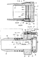
- Fig .1 ein erfindungsgemäßes Laser-Behandlungsinstrument im Längsschnitt;
- Fig. 2 und 3 ein Handstück und ein Anschlußstück des Laser-Behandlungsinstrumentes im Längsschnitt;
- Fig. 4 die in
Figur 1 mit X gekennzeichnete Einzelheit in entkuppelter Position in vergrößerter Darstellung; - Fig. 5 die in
Figur 1 mit Y gekennzeichnete Einzelheit in vergrößerter Darstellung; - Fig. 6 ein erfindungsgemäßes dentales Laser-Behandlungsgerät in perspektivischer Vorderansicht;
- Fig. 7 das Laser-Behandlungsgerät in vergrößerter Schnittdarstellung der Lagerung eines Gelenkgliederarms und einer Ausgleichseinrichtung für das Eigengewicht des Gelenkgliederarms;
- Fig. 8 eine Drehlager/Steckkupplung-Kombination im vertikalen Schnitt;
- Fig. 9 ein wesentliches Funktionsteil der Ausgleichseinrichtung im vertikalen Schnitt in IX-IX Fig. 3;
- Fig. 10 eine der
Figur 7 entsprechende Ansicht mit einer abgewandelten Gewichts-Ausgleichseinrichtung; - Fig. 11 das Laser-Behandlungsgerät mit einer weiter abgewandelten Gewichts-Ausgleichseinrichtung in der Seitenansicht;
- Fig. 12 wesentliche Einzelteile der Gewichts-Ausgleichseinrichtung nach
Figur 11 in vergrößerter Darstellung; - Fig. 13 ein erfindungsgemäße dentales Laser-Behandlungsgerät in abgewandelter Ausgestaltung und in perspektivischer Vorderansicht;
- Fig. 14 einen dentalen Behandlungsplatz mit einem Behandlungsstuhl, dem das erfindungsgemäße Laser-Behandlungsgerät zugeordnet ist, in perspektivischer Darstellung;
- 1 shows a laser treatment instrument according to the invention in longitudinal section;
- Figures 2 and 3 a handpiece and a connector of the laser treatment instrument in longitudinal section.
- 4 shows the detail marked X in FIG. 1 in the uncoupled position in an enlarged view;
- 5 shows the detail marked Y in FIG. 1 in an enlarged representation;
- 6 shows a dental laser treatment device according to the invention in a perspective front view;
- 7 shows the laser treatment device in an enlarged sectional view of the mounting of an articulated arm and a compensation device for the dead weight of the articulated arm;
- 8 shows a rotary bearing / plug-in coupling combination in vertical section;
- Fig. 9 shows an essential functional part of the compensation device in vertical section in IX-IX Fig. 3;
- 10 shows a view corresponding to FIG. 7 with a modified weight compensation device;
- 11 shows the laser treatment device with a further modified weight compensation device in a side view;
- 12 essential individual parts of the weight compensation device according to FIG. 11 in an enlarged representation;
- 13 shows a dental laser treatment device according to the invention in a modified configuration and in a perspective front view;
- 14 shows a perspective view of a dental treatment station with a treatment chair, to which the laser treatment device according to the invention is assigned;
Das Handstück 2 ist bei der vorliegenden Ausgestaltung mit einem hinteren Hülsenteil 11 und einem vorderen Hülsenteil bzw. Kopfteil 12 zweiteilig ausgebildet und an der Trennstelle 13 zusammengesteckt. Dabei ist das Kopfteil 12 mit einem Zapfen in das Hülsenteil 11 fest eingesteckt, so daß es für die übliche Handhabung nicht lösbar ist. Die Trennstelle 13 ist vorzugsweise aus Gründen einer einfachen Fertigung und Montage vorgesehen. Am hinteren Ende des Handstückes 2 ist das Hülsenteil 11 durch ein im Querschnitt etwas größer bemessenes Hülsenendstück 14 verlängert, das eine Außenschulter am hinteren Hülsenrand übergreift, und in dem eine Lagerhülse 15 fest eingesetzt ist, deren vorderes Ende in den hinteren Endbereich des Hülsenteils 11 hineinragt. Die zylindrische Innenwandung der Lagerhülse 15 bildet ein Steckloch 17, in das ein koaxialer, hohlzylindrischer Steckzapfen 18 des Anschlußstückes 4 mit geringem Bewegungsspiel einsteckbar ist und in der eingesteckten Position elastisch verrastbar ist. Hierzu dient ein radial wirksamer, gespaltener Federring 19, der in einer im hinteren Bereich des Steckzapfens 18 angeordneten Umfangsnut 21 mit Bewegungsspiel sitzt und dabei so groß bemessen ist, daß sein Außenmantel die Außenmantelfläche 22 des Steckzapfens 18 geringfügig überragt. Beim Einstecken des Steckzapfens 18 in das Steckloch 17 wird der Federring 19 zusammengedrückt. In der Steckendstellung rastet er elastisch in eine entsprechende Innenumfangsnut 23 im hinteren Bereich der Lagerhülse 15 elastisch ein. Beim Lösen der so gebildeten Steck/Dreh-Kupplung 6 durch eine leichte, axiale Kraftausübung wird der Federring 19 überdrückt, was durch Anlaufschrägen am Federring 19 und/oder an der Innenwandung 16 ermöglicht bzw. erleichtert wird.The
Der Steckzapfen 18 ragt koaxial von einem Flansch 24 nach vorne, der einen radialen Ansatz 25 aufweist. Rückseitig ragt vom Flansch 24 ein koaxialer Lagerring 26 nach hinten, der an seiner Außenmantelfläche ein Außengewinde 27 und im Bereich der hinteren Hälfte seiner Innenmantelfläche ein Innengewinde 28 aufweist. Die vordere Hälfte der Innenmantelfläche bildet ein zylindrisches Paßloch 29, in das passend eine optische Linse 31 eingesetzt ist, was am besten aus Figur 4 (Einzelheit X) ersichtlich ist. Zur axialen Lagerung der Linse 31 dient eine vorzugsweise ebene Schulter 32 zwischen dem Paßloch 29 und dem im Querschnitt etwas kleiner bemessenen zylindrischen Durchgangsloch 33 im Anschlußstück 4, das sich durch den Flansch 24 und den Steckzapfen 18 erstreckt. Zur Befestigung der Linse 31 dient eine mit Außengewinde und mit rückseitigen, nicht dargestellten Drehangriffselementen, z.B. kleinen einander diametral gegenüberliegenden Löchern versehene Ringmutter 34, mit der die Linse 31 mittels eines dazwischen angeordneten Rings 35 aus elastischem Material, wie z.B. Gummi gegen die Schulter 32 gedrückt ist.The
Das Anschlußstück 4 ist mit seinem Außengewinde 27 in ein Gewindeloch 36 des hülsenförmigen Armglieds 5 eingeschraubt, das um seine Längsachse 37, die mit der Längsachse 37a des Handstückes 2 zusammenfällt, drehbar an einem hinteren, sich quer, vorzugsweise rechtwinklig, zum vordersten Armglied 5 erstreckenden, ebenfalls hülsenförmigen Armglied 38 gelagert ist. Bei der vorliegenden Ausgestaltung weist der insgesamt nicht dargestellte Gliedergelenkarm mehrere Armglieder in einer solchen Anzahl und Anordnung auf, daß die zur Behandlung erforderliche Beweglichkeit des Laser-Behandlungsinstrumentes gewährleistet ist. Der Laserstrahl wird in einer nichtdargestellten Laserstrahlerzeugungseinrichtung erzeugt, an der das hintere Ende des Gliedergelenkarmes gehalten ist. Dabei wird der Laserstrahl durch die hülsenförmigen Armglieder geleitet. In den zwischen den Armgliedern vorhandenen Armgelenken, hier Drehgelenk 39 zwischen den Armgliedern 5 und 38 wird der Laserstrahl mittels einer z.B. durch einen Spiegel oder ein Prisma 41 gebildeten Umlenkeinrichtung umgelenkt, so daß er koaxial aus dem Armglied 5 austritt und sich in Längsachsrichtung 37a durch die Linse 31, das Durchgangsloch 33 des Anschlußstückes 4 und das Handstück 2 erstreckt. Der Hohlraum des hülsenförmigen Handstückes 2 bzw. ein im Kopfteil 12 axialer zylindrischer Kanal 42 endet in axialer Richtung am vorderen Ende des Kopfteiles 12 und erstreckt sich dann vorzugsweise rechtwinklig nach außen. Im Bereich dieser Abknickung ist eine Laserstrahl-Umlenkeinrichtung, vorzugsweise ein Spiegel oder ein Prisma 43, positioniert, das den vorzugsweise durch die Linse 31 im Prisma 43 fokussierten Laserstrahl so bricht, daß er den Austritt 3 durchquert und fokussiert auf die mit A angedeutete Behandlungsstelle trifft, die sich im Bereich des Schnittpunktes der Achsen des Austritts 3 und der Mediendüse 9 befindet.The connector 4 is screwed with its
Es ist vorteilhaft, die Umlenkeinrichtung justierbar anzuordnen, um Toleranzunterschiede des Laser-Behandlungsinstrumentes 1 ausgleichen zu können.It is advantageous to arrange the deflection device in an adjustable manner in order to be able to compensate for differences in tolerance of the
Vorzugsweise ist das Prisma 43 gemäß der die Einzelheit Y zeigenden Figur 5 in einem Einsatzstück 49 angeordnet bzw. gelagert, das im Sinne einer Patrone in den den Austritt 3 bildenden Querkanal 45 oder in den Endbereich des Kanals 42 einsetzbar ist. Wie Figur 5 deutlich zeigt, ist das Paß- oder Einsatzstück 49 gegen eine vorzugsweise ebene Paßfläche 46 gedrückt oder gespannt, die sich vorzugsweise parallel zur Längsachse 37a erstreckt und den Grund des Querkanals 45 bildet. Zur Halterung des Einsatzstückes 49 dient eine Ringmutter 47, die im Querkanal 45 eingeschraubt ist und vorzugsweise mittels eines elastischen Ringes gegen das Einsatzstück 49 drückt. Um die durch einen Spiegel oder das Prisma 43 gebildete Umlenkeinrichtung vor Teilchen zu schützen, die bei der Bearbeitung eines Zahnes mit dem Laserstrahl abplatzen, ist ihr eine laserstrahltransparente Schutzscheibe 48 nachgeordnet, die austauschbar im Bereich des Austritts 3 gehalten und somit von Zeit zu Zeit durch eine neue ersetzbar ist, wenn sie z.B. blind geworden ist. Die Schutzscheibe 48 kann aus Glas oder auch Kunststoff bestehen. Sie ist vorzugsweise in einem Haltering 44 mit Außengewinde befestigt, der in dem Querkanal 45 oder in die Ringmutter 47 einschraubbar ist, wozu entsprechende Gewinde vorzusehen sind. Vorzugsweise weist der Haltering 44 einen vorderseitigen Flansch 51 auf, in dem vorzugsweise durch Außennuten gebildete Drehangriffselemente zum Ein- und Ausschrauben vorgesehen sind. Die Einschraubtiefe der Ringmutter 47 oder des Halteringes 44 ist vorzugsweise durch eine Anschlagschulter begrenzt, so daß das Einsatzstück 49 durch die Andruckkraft nicht überbelastet werden kann, sondern maximal durch die Elastizität des vorbeschriebenen elastischen Ringes in seine Paßstellung vorgespannt ist.The
Für die Medienzuführung sind zwei Medienschläuche 52a, 52b vorgesehen, die sich längs des Gliedergelenkarmes erstrecken und z.B. außen an diesem gehalten sind. Die Medienschläuche 52a, 52b und weitere Abschnitte der allgemein mit 7 bezeichneten Medienleitungen hier zwei Medienleitungen, liegen in der Zeichnungsansicht hintereinander, so daß jeweils nur eine Medienleitung 7 sichtbar ist. Die Medienschläuche 52a, 52b sind jeweils mittels eines rückseitig abstehenden Anschlußröhrchens 53a, 53b an das Anschlußstück 4 angeschlossen, das in ein achsparalleles Loch 54a, 54b im Ansatz 25 fest eingesetzt ist. Vom Loch verläuft ein Kanal 55a, 55b radial einwärts bis zu einem axialen Kanal 56a, 56b, der sich nach vorne bis in den Bereich vor dem Federring 19 erstreckt und mit einem radial nach außen verlaufenden Kanalabschnitt 57a, 57b an der Außenmantelfläche 22 des Steckzapfens 18 ausmündet. Dabei sind die beiden in Umfangsrichtung versetzten Kanalabschnitte 57a, 57b der beiden Medienleitungen 7 in einem axialen Abstand a voneinander angeordnet. Jedem Kanalabschnitt 57a, 57b bzw. seiner Mündungsöffnung ist in der Innenwandung 16 der Lagerhülse 15 eine Umfangsnut 58a, 58b gegenüberliegend zugeordnet. Zur axialen Abdichtung der Kanalabschnitte 57a, 57b bzw Umfangsnuten 58a, 58b sind drei Dichtungsringe 59a, 59b, 59c vorgesehen, von denen sich jeweils zwei axial vor und hinter dem zugehörigen Kanalabschnitt 57a, 57b bzw. der zugehörigen Umfangsnut 58a, 58b befinden. Die vorzugsweise durch O-Ringe gebildeten Dichtungsringe befinden sich jeweils in einer Umfangsnut, die vorzugsweise in der Außenmantelfläche 22 des Steckzapfens 18 angeordnet ist. Von den Umfangsnuten 58a, 58b führt jeweils ein radialer Kanalabschnitt 61a, 61b ab, der jeweils mit einem zugehörigen radialen Abschnitt 62a, 62b in einem Einsatzstück 63 korrespondiert, das in einer zugehörigen Ausnehmung 64 bzw. in einem zugehörigen Loch in der Lagerhülse 15 sitzt. Jeder radiale Kanalabschnitt 62a,62b steht mit einem axialen Kanalabschnitt 65a, 65b im Einsatzstück 63 in Verbindung, der an dessen Frontseite ausmündet. Die axialen Kanalabschnitte 65a, 65b sind ebenfalls in Umfangsrichtung versetzt angeordnet. Die Trennfugen zwischen den zueinander gehörigen radialen Kanalabschnitten 61a, 61b und 62a, 62b sind jeweils durch einen Dichtungsring 66a, 66b abgedichtet, der in einer Nut in der vorzugsweise ebenen Grundfläche der Ausnehmung 64 oder in der ihr zugewandten Innenfläche des Einsatzstückes 63 angeordnet ist.For the media supply, two media hoses 52a, 52b are provided, which extend along the articulated arm and are held on the outside thereof, for example. The media hoses 52a, 52b and further sections of the media lines, generally designated 7 here, two media lines, lie one behind the other in the drawing view, so that only one
In die vorderseitige Mündungsöffnung jedes axialen Kanalabschnittes 65a, 65b ist ein Röhrchen 67a, 67b fest und dicht eingesetzt. Die Röhrchen führen das zugehörige Medium (Druckluft, Wasser) zur Mediendüse 9.A
Bei der vorliegenden Ausgestaltung sind die vorderen Enden der Röhrchen 67a, 67b fest und dicht in die hinteren Öffnungen von axialen Kanälen 68a, 68b fest und dicht eingesetzt, die sich zu einer die Mediendüse 9 aufnehmenden Düsenbohrung 69 erstrecken, deren Mittelachse schräg, vorzugsweise unter einem Winkel von 45° zur Längsachse 37a angeordnet ist. Die Mediendüse 9 weist ein hülsenförmiges Düsenaußenteil 71 und ein hülsenförmiges, im letzten aufgenommenen Düseninnenteil 72 auf, die als Baueinheit mit einem am Düsenaußenteil 71 angeordneten Außengewinde in die Düsenbohrung 69 einschraubbar sind. Das Wasser wird koaxial zum mittels eines Dichtungsringes abgedichteten Düseninnenteil 72 zugeführt, dessen Hülsenspitze in einem geringen Abstand vor der gemeinsamen Düsenöffnung 73 des Düsenaußenteiles 71 endet. Die Druckluft wird durch einen zwischen dem Düsenaußenteil 71 und dem Düseninnenteil 72 verlaufenden axialen Kanal zur Düsenöffnung 73 zugeführt. Im vor der der Düsenöffnung 73 vorhandenen Freiraum bzw Spalt erfolgt eine selbsttätige Vermischung der Druckluft und des Wasser zu einem aus der Düsenöffnung 73 austretenden Gemisch bzw. Spray.In the present embodiment, the front ends of the
Der vorbeschriebenen abgedichtete Verlauf der Medienleitungen 7 quer durch die Trennfuge zwischen dem einen Kupplungszapfen bildenden Steckzapfen 18 und dem eine Kupplungsbuchse bildenden Steckloch 17 ermöglicht ein Drehen des Handstückes 2 in der Steck/Dreh-Kupplung 6 um 360° und mehr, ohne daß eine Beeinträchtigung zu fürchten ist. Die vorbeschriebene Steck/Dreh-Kupplung 6 ermöglicht auch einen großen Querschnitt des Durchgangsloches 33, was der Laserstrahldurchführung und -leitung zugute kommt.The above-described sealed course of the
Einer oder beiden Medienleitungen 7, vorzugsweise der Wasser führenden Medienleitung, ist ein einstellbares Drosselventil 74 zugeordnet, mit dem die Strömungsmenge und/oder der Druck einstellbar ist, mit dem das zugehörige Medium an der Mediendüsen 9 austritt. Bei der vorliegenden Ausgestaltung ist das Drosselventil 74 im Ansatz 25 angeordnet. In diesem Bereich ist es von außen mit einem Verstellwerkzeug leicht zugänglich. Das Drosselventil 74 kann in einem axialen oder radialen Kanal angeordnet sein, der in den zugehörigen Kanalabschnitt der Medienleitung 7 mündet, so daß er vorzugsweise ein- und ausschraubbare Ventilkörper den zugehörigen Medienkanalquerschnitt verändern kann. Vorzugsweise weist das Drosselventil 74 eine durch einen Dichtungsring an ihrem Umfang abgedichtete und in eine radiale oder axiale Bohrung 75 eingeschraubte Schraube 74a auf, deren freies Ende vorzugsweise angespitzt ist und deren Kopfende ein Werkzeugangriffselement zum Drehen aufweist. Vorzugsweise ist die Bohrung 75 parallel zur Längsachse 37a und außerhalb des Umfangs des Handstücks 2 angeordnet und eine nach vorne durchgehende Verlängerung des Waser-Kanals 54a, so daß die Schraube 74a von vorne zugänglich ist.One or both
Die Schraubenspitze kann mit dem Kanal im zugehörigen Röhrchen 53a zusammenwirken.The screw tip can interact with the channel in the associated
Das in Figur 6 dargestellte Laser-Behandlungsgerät 101 besteht aus einem Ständer 102 mit einem Ständerfuß 103, einem etwa horizontalen Tragarm 104, der um eine vertikale Drehachse 105 am Ständer 102 frei drehbar gelagert ist, ein Steuergerät 106, das am freien Ende des Tragarms 104 um eine vertikale Schwenkachse 107 frei schwenkbar gelagert ist, einem Gelenkgliederarm 108, der um eine horizontale Drehachse 109a frei drehbar in einem Drehlager 109 des Steuergerätes 106 frei drehbar gelagert ist und einem am Steuergerät 106 gehaltenen Tragteil 112 zur Halterung des freien Endbereichs des Gelenkgliederarms 108 in dessen Nichtgebrauchsstellung.The
Bei der vorliegenden Ausgestaltung ist der Ständerfuß 103 durch einen würfel- bzw. quaderförmigen Kasten 113 gebildet, an dessen Frontseite und/oder vorderen Oberseitenbereich elektrische Steuerelemente angeordnet sind. Hierbei kann es sich um einen vorzugsweise durch ein Schloß abschließbaren Hauptschalter 114, ein Ein/Aus-Schalter 115 und einen Sicherheits-Ausschalter 116 handeln, wobei die beiden letzteren vorzugsweise Tastenschalter sind. Es ist vorteilhaft, die Steuerelemente an einer im oberen vorderen Eckenbereich des Kastens 113 vorhandenen, nach hinten schräg aufwärts verlaufenden Schrägfläche 117 anzuordnen. In einer solchen Anordnung können die Steuerelemente 115 und 116 mit dem Fuß des Behandlers leicht und sicher bedient werden. Vorzugsweise ist in dem ein Basisteil bildenden Ständerfuß 103 ein Großteil der vorhandenen Steuereinrichtung angeordnet. Hierbei kann es sich um einen Wasser-Vorratsbehälter, einer Pumpe für die Wasserversorgung, ein Lasernetzteil und einen Mikroprozessor handeln.In the present embodiment, the stand base 103 is formed by a cube-shaped or cuboid box 113, on the front and / or front top area of which electrical control elements are arranged. This can be a main switch 114, an on / off switch, preferably lockable by a
Der Ständer 102 besteht vorzugsweise aus einer im oder am Kasten 113 befestigten, vorzugsweise teleskopierbaren Tragsäule 118, bestehend aus einem unteren Säulenteil 118a, in dem ein oberes Säulenteil 118b vertikal verschiebbar und in der jeweiligen Schiebestellung feststellbar geführt ist. Der Tragarm 104 ist vorzugsweise ein sogenannter Knie-Hebelarm mit zwei Armteilen 104a,104b, die an ihren einander zugwandten Enden in einem Knie-Hebelgelenk um eine vertikale Schwenkachse 119 schwenkbar miteinander verbunden sind.The
Das Drehlager 109 befindet sich an einer Seite des quaderförmigen Gehäuses 121 des Steuergerätes 106, so daß sich die Drehachse 109a parallel zur Vorderseite des Laser-Behandlungsgeräts 101 erstreckt. Bei Rechtsausführung (für Rechtshänder) ist das Drehlager 109 rechts angeordnet, und das Tragteil 112 befindet sich im linken Endbereich des Steuergeräts 106. Als Tragteil 112 kann ein plattenförmiges Ablageteil dienen, das vorzugsweise im vorderen Eckenbereich der Gehäuseecke angeordnet ist, die dem Drehlager 109 abgewandt ist.The
Der Gelenkgliederarm 108 besteht aus wenigstens drei Armgliedern, die um senkrecht zueinander verlaufende Dreh- oder Schwenkachsen drehbar bzw. schwenkbar gelagert sind. Bei der vorliegenden Ausgestaltung besteht der Gelenkgliederarm 108 aus sechs Armgliedern, von denen das erste Armglied 108a, das armseitige Lagerteil des Drehlagers 109 bildet. Die weiteren Armglieder 108b, 108c, 108d, 108e und 108f sind jeweils um eine zur vorherigen Drehachse rechtwinklig verlaufende Drehachse 109b, 109c, 109d, 109e, 109f am freien Ende des jeweils vorherigen Armgliedes frei drehbar gelagert. Am freien Ende des vordersten Armgliedes 108f ist ein mechanischer Anschluß, insbesondere eine Verschraubung mit vorzugsweise Innengewinde angeordnet, mittels der ein Laser-Behandlungsinstrument 122 am Gelenkgliederarm 108 lösbar befestigbar ist das dem nach Fig. 1 bis 5 entsprechen kann. Die Längsmittelachse 123 des Laser-Behandlungsintruments 122 erstreckt sich senkrecht zur Drehachse 109. Hierdurch erhält es eine vorteilhafte Anordnung für die Benutzung im Mundraum eines Patienten.The articulated
Im Steuergerät 106 befindet sich eine im einzelnen nicht dargestellte Laserstrahl-Erzeugungseinrichtung, die den in Figur 7 mit einem Pfeil 124 verdeutlichten Laserstrahl koaxial durch das Drehlager 109 hindurch, d.h. koaxial zur Drehachse 109a, in den Gelenkgliederarm 108 einstrahlt. Das Drehlager 109 ist hierzu hohl ausgebildet. Auch die Armglieder 108a bis 108f sind zur Durchführung des Laserstrahls 124 hohl ausgebildet, wobei in den Durchgangskanal des hohlen Gelenkgliederarms 108 ein Lichtleitsystem integriert ist, mit dem der Laserstrahl 124 zum freien Ende des Gelenkgliederarms 108 geleitet und koaxial in das Laser-Behandlungsinstrument 122 eingeführt werden kann. Das optische Leitsystem weist in den zwischen den Armgliedern 108a bis 108f vorhandenen Gelenken andeutungsweise dargestellte Spiegel 125 oder Prismen auf, die eine Umlenkung bzw. Brechung des Laserstrahls 124 um jeweils 90° in Längsrichtung des Gelenkgliederarms 108 bewirken. Der Spiegel 125 oder das Prisma ist jeweils am vorherigen Armglied befestigt, wobei er den Laserstrahl 124 in Längsrichtung des nachfolgenden Armglieds bricht.In the
Der Gelenkgliederarm 108 ist durch eine als Schnellkupplung ausgebildete Steckkupplung 131 mit dem Steuergerät 106 lösbar verbunden. Die Steckkupplung 131 umfaßt einen zylindrischen Kupplungszapfen und eine ihn mit geringem Bewegungsspiel aufnehmende zylindrische Kupplungsbuchse. Beim vorliegenden Ausführungsbeispiel ist der Kupplungszapfen 132 am hintersten Armglied 108f einteilig oder als Anbauteil daran (Fig. 8) vorgesehen, wobei bei nicht einteiliger Ausführung der Kupplungszapfen 132 mit dem letzten Armglied 108f verschraubbar sein kann, wozu ein Außengewinde 133 auf einem koaxialen Hülsenvorsprung 134 dienen kann, mit dem der Kupplungszapfen 132 in ein Innengewinde (nicht dargestellt) des Armglieds 108f schraubbar ist. Der Zapfenabschnitt 132a des Kupplungszapfens 132 erstreckt sich koaxial von einem Flansch 135 nach hinten, von dessen anderen Seite sich der Hülsenvorsprung 134 nach vorne erstreckt. Der Kupplungszapfen 132 ist von einem zylindrischen Durchgangsloch 136 durchsetzt, so daß der Zapfenabschnitt 132a hülsenförmig ist. Der vordere Außenrand des Kupplungszapfens 132 ist gerundet, um sein Einstecken in die Kupplungsbuchse 137 zu erleichtern. Die Steckupplung 131 ist in der Schließstellung ihrer Kupplungsteile elastisch verrastbar und durch Überdrücken der Verrastung bei axialer Bewegung des beweglichen Kupplungsteils lösbar. Hierzu dient ein radial wirksamer, gespaltener Federring 139, der in einer im hinteren Bereich des Zapfenabschnitts 132a des Steckzapfens 132 angeordneten Umfangsnut 141 mit Bewegungsspiel sitzt und dabei so groß bemessen ist, daß seine Außenmantelfläche die Außenmantelfläche 142 des Steckzapfens 132 überragt. Beim Einstecken des Steckzapfens 132 in das Steckloch 143 der Kupplungsbuchse 137 wird der Federring 139 zusammengedrückt. In der Steckendstellung rastet er in eine entsprechend geformte Innenumfangsnut 144 im vorderen Bereich der Kupplungsbuchse 137 elastisch ein. Beim Lösen der so gebildeten Steck-/Dreh-Kupplung 131 durch eine verhältnismäßig leichte, axiale Kraftausübung wird der Federring 139 überdrückt, was durch Anlaufschrägen am Federring 139 und/oder an der Innenwandung des Stecklochs 143 ermöglicht, bzw. erleichtert wird.The articulated
Die Kupplungsbuchse 137 bildet das dem Gelenkgliederarm 108 zugeordnete Drehlagerteil des Drehlagers 109. Das dem Steuergerät 106 zugeordnete Drehlagerteil kann zum Beispiel an der seitlichen Gehäusewand 121a des Gehäuses 121 gelagert sein. Bei der vorliegenden Ausgestaltung ist in der seitlichen Gehäusewand 121a ein rundes Loch 145 vorgesehen, in das mit geringem Bewegungsspiel ein von der Kupplungsbuchse 137 koaxial vorragender zylindrischer Ringansatz 146 mit geringem Bewegungsspiel einfaßt. Zur axialen Sicherung der Kupplungsbuchse 137 im Loch 145 dient eine Lagerscheibe 147, die an der ebenen Stirnfläche des Ringansatzes 146 anliegt, sowie damit z.B. durch Schrauben befestigt ist und den außenseitigen Lochrand des Loches 145 überragt. Die Kupplungsbuchse 137 ist somit im Loch 145 sicher gelagert und dabei frei drehbar.The
Zur Versorgung des Laser-Behandlungsintruments 122 sind zusätzlich zum Laserstrahl-Leitsystem weitere Medienleitungen zur Zuführung von Medien vorgesehen, die sich durch das Drehlager 109 und die Steckkupplung 131 sowie entlang des Gelenkgliederarms 108 erstrecken und in dessen vorderen Endbereich an das Laser-Behandlungsinstrument 122 angeschlossen werden können. Bei solchen weiteren Medien kann es sich um Wasser, Luft, Wasser-Luftgemisch, elektrischer Strom und/oder einen sogenannten Pilotstrahl handeln. Im folgenden werden beispielhaft zwei Medienzuführungen insbesondere für Luft und Wasser oder Wasser-Luftgemisch in jeweils einer von zwei Medienleitungen 148 beschrieben. Im Gegensatz zum Laserstrahl, für den es bei seiner Führung entlang des Gelenkgliederarms 108 und durch das Drehlager 109 und die Steckkupplung 131 keiner Abdichtung bedarf und der vorzugsweise koaxial zum Drehlager 109 angeordnet ist, bedarf es bei Medienleitungen für Behandlungs-Luft und/oder-Flüssigkeit, wie insbesondere Wasser oder Spray, einer abgedichteten Zuführung, insbesondere im Bereich der Steckkupplung 131 und der lösbaren Verbindung zwischen dem vordersten Armglied 108f und dem Behandlungsinstrument 122, die vorzugsweise ebenfalls durch eine Schnell- oder Steckkupplung gebildet ist. Diese Medienleitungen 148 erstrecken sich von der im Ständerfuß 103 angeordneten Pumpe oder von einer im Steuergerät 106 angeordneten Pumpe zur Kupplungsbuchse 137, wobei es sich um flexible Medienschläuche 149 handeln kann, die mit Leitungsanschlüssen 151 an der Kupplungsbuchse 137 zum Beispiel durch Aufstecken verbindbar sind. Bei der vorliegenden Ausgestaltung befinden sich die Leitungsansschlüsse 151 an der Außenmantelfläche 152 der Kupplungsbuchse 137, und es führt jeweils ein Medienkanal 153a, 153b radial einwärts zu einer zugehörigen Ringnut 154a, 154b in der Innenmantelfläche 156 der Kupplungsbuchse 137, die einen axialen Abstand a voneinander aufweisen. Im Kupplungszapfen 132 ist jeweils ein kurzer radialer Kanalabschnitt 157a, 157b vorgesehen, der die Außenmantelfläche 142 des Kupplungsabschnitts 132a in der Radialebene der zugehörigen Ringnut 154a, 154b durchsetzt und somit damit in Verbindung steht. Von den Kanalabschnitten 157a, 157b erstrecken sich innerhalb der Wandung des Kupplungszapfens 132 Kanalabschnitte 159a, 159b prallel zur Längsmittelachse des Kupplungszapfens 132 nach außen. An die axialen Kanalabschnitte 159a, 159b schließen sich im Flansch 135 radial nach außen verlaufende Kanalabschnitte 161a, 161b an, von denen nur einer sichtbar ist, und von denen achsparallele Kanalabschnitte 162a, 162b ausgehen, die sich nach außen erstrecken und an der Vorderseite des Flansches 135 austreten. Die vorbeschriebene Kanalabschnitte sind durch Bohrungen gebildet, wobei die Kanalabschnitte 159a, 159b von einer Innenschulter des Durchgangslochs 136 des Kupplungszapfens 132 und die Kanalabschnitte 161a, 161b von der Umfangsfläche des Flansches 135 her eingebohrt und endseitig durch Stopfen verschlossen sind. Die Kanalabschnitte 162a, 162b sind im Querschnitt größer bemessen und es sind darin Schlauchanschlußelemente, hier Anschlußhülsen 163 fest eingesetzt, die sich in einem Abstand von ein paar Milimeter neben dem zugehörigen Armglied 108f befinden. Auf die beiden vorhandenen Anschlußhülsen 163 sind zwei flexible Medienschläuche 160 aufgesteckt, die sich entlang des Gelenkgliederarms 108 zu dessen vorderen Ende hin erstrecken zwecks Versorgung des Laser-Behandlungsinstruments 122 und am Gelenkgliederarm 108 gehalten sind z.B. durch Badagen. Das Laser-Handstück ist durch eine mit der vorbeschriebenen Steck/Dreh-Kupplung vergleichbare Steck/Dreh-Kupplung 164 lösbar mit dem vordersten Armglied 108f verbunden ist. An dieser Kupplungsstelle ist vorzugsweise ein nach vorne ragender Kupplungszapfen vorgesehen, der in eine Kupplungsbuchse des Laser-Handstücks einsteckbar ist und mit seinem hinteren Ende mit dem vordersten Armglied 108f verschraubt ist. Dieser im einzelnen nicht dargestellte Kupplungszapfen ist spiegelbildich zum Kupplungszapfen 132 angeordnet und ausgebildet, so daß auch die Verschraubung und die Durchführung der Medienleitungen 148 durch den vorhandenen Flansch und die Kupplung entsprechend der Ausgestaltung bei der Steckkupplung 131 ausgeführt sein können, wobei die Medien im Laser-Handstück zu dem Behandlungswerkzeug zugeordneten Austrittsöffnungen geführt sind.To supply the
Zur Abdichtung der Medien bei ihrem Durchtritt durch den zylindrischen Kupplungsspalt können zu beiden Seiten der Ringnuten 154a, 154b oder der radialen Kanalabschnitte 157a, 157b Ringnuten 165 in der Kupplungsbuchse 137 oder im Kupplungszapfen 132 angeordnet sein, in die Dichtungsringe, vorzugsweise O-Ringe 166 eingesetzt sind.To seal the media as they pass through the cylindrical coupling gap, annular grooves 165 can be arranged on both sides of the
Ein soweit beschriebener Gelenkgliederarm 108 ist aufgrund seines Eigengewichts mit einem nach unten gerichteten Drehmoment behaftet, dem der Behandler bei der Behandlung beim manuellen Halten des Laser-Behandlungsinstruments 122 entgegenzuwirken hat. Um dies zu erleichtern ist dem Gelenkgliederarm 108 eine Ausgleichsvorrichtung 171 zugeordnet, die sein Eigengewicht in seiner auf dem Tragteil 112 abgelegten Ausgangsstellung oder in einer mittleren Stellung seines Bewegungsbereichs zumindest teilweise ausgleicht, d.h. dem Eigengewicht entgegenwirkt, so daß der Gelenkgliederarm 108 wenigstens teilweise gewichtsentlastet ist.An articulated
Vorzugsweise ist der Gelenkgliederarm 108 so angeordnet, daß sein hinterstes Armglied 108a bzw. dessen bezüglich der Drehachse 109a radial wegweisender Schenkel 172 sich in seiner Ausgangsstellung schräg nach vorne (Fig. 7) oder schräg nach hinten (Fig. 11 und 12) und dabei vorzugsweise nach unten erstreckt. Die Ausgleichsvorrichtung 171 ist so ausgebildet und angeordnet, daß sie ein dem Eigengewicht entgegenwirkendes Drehmoment am hinteresten Armglied 108a erzeugt.The articulated
Gemäß Figuren 7, 9 und 10 ist eine Ausgleichsvorrichtung 171a, 171b vorgesehen, die durch eine Feder die angestrebte Ausgleichskraft erzeugt. Die Feder greift in einem radialen Abstand von der Drehachse 109a am hinteresten Armglied 108a an, vorzugsweise an der Kupplungsbuchse 137. Gemäß Figur 7 ist eine am Gehäuse 121 abgestützte Zugfeder 173 vorgesehen, die unmittelbar oder mittels eines Zugseils 174 an der Kupplungsbuchse 137 angreift. Um dabei einen gewissen Drehwinkelbereich für das hinterste Armglied 108a zu gewährleisten, ist das Zugseil 174 über diesen bestimmten Drehwinkelbereich am Umfang der Kupplungsbuchse 137 aufgewickelt, vorzugsweise auf der Umfangsfläche 175 eines Flansches 176, der bei der vorliegenden Ausgestaltung das Drehlagerteil bildet. Das Zugseil 174 ist an seinem Zugende z.B. mittels einer Schraube 174a an der Kupplungsachse 137 befestigt. Durch einen an der Kupplungsbuchse 137 befestigten Anschlag oder Stift 174b, der mit einem gehäusefesten Anschlag 174c zusammenwirkt, kann die durch die Ausgleichsfeder 173 erzeugte maximale Drehbewegung begrenzt werden.According to FIGS. 7, 9 and 10, a compensation device 171a, 171b is provided which generates the desired compensation force by means of a spring. The spring engages at a radial distance from the axis of
Um den vorhandenen Raum besser ausnutzen zu können, ist bei der Ausgestaltung gem. Figur 7 die Zugfeder 173 in der horizontalen Längsrichtung des sich parallel zur Vorderseite länglich erstreckenden Gehäuses 121 darin vorzugsweise in dessen hinteren Bereich angeordnet, wobei das Zugseil 174 um eine drehbar am Gehäuse 121 gelagerte Umlenkrolle 177 umgelenkt ist.In order to make better use of the available space, the design according to 7 shows the
Zwischen der Kupplungsbuchse 137 und dem Steckzapfen 132 ist eine Drehmitnahmeverbindung 170 vorgesehen, mittels der das von der Feder 173 erzeugte Ausgleichsmoment auf den Gelenkgliederarm 108 übertragen werden kann. Gemäß Figur 8 wird die Drehmitnahmeverbindung 170 durch mehrere, auf einem koaxialen Teilkreis angeordnete Drehmitnahmestifte 170a gebildet, die in Drehmitnahmelöcher 170b einfassen und somit ebenfalls eine Steckkupplung bilden, die beim Ein- und Ausstecken des Steckbolzens 132 selbsttätig geschlossen und geöffnet wird. Vorzugsweise sind die Drehmitnahmestifte 170a in achsparallelen Löchern des Flansches 135 fest eingesetzt und sie ragen davon nach hinten achsparallel vor, um in die zugehörigen Drehmitnahmelöcher 170b in der Kupplungsbuchse 137 einfassen zu können. Für eine Drehmitnahmeverbindung 170 reicht ein Drehmitnahmestift 170a aus. Vorzugsweise sind mehrere, z.B. vier oder sechs Drehmitnahmestifte 170a und zugehörige Drehmitnahmelöcher 170b in gleichen Winkelabständen voneinander angeordnet. Hierdurch werden mehrere Kupplungsstellungen geschaffen, die in Umfangsrichtung versetzt zueinander angeordnet sind. Hierdurch wird eine Einstellvorrichtung für die Größe der Federkraft bzw. des Ausgleichsmoments geschaffen, weil das hinterste Armglied 108a in unterschiedlichen Drehstellungen an die Kupplungsbuchse 137 angekuppelt werden kann und somit die Vorspannung der Ausgleichsfeder und/oder die Ausgangsdrehstellung des hintersten Armglieds 108a variiert und wahlweise eingestellt werden kann.A rotary driving connection 170 is provided between the
Es ist vorteilhaft, die mit dem Pfeil 178 verdeutlichte Ausgleichskraft in Abhängigkeit von der Drehung des hintersten Armglieds 108a so zu verändern, daß sie mit zunehmendem Winkelabstand des Schenkels 172 von der vertikalen Mittelebene 179 zunimmt. Hierdurch können Veränderungen des Eigengewichtdrehmoments 181 berücksichtigt werden, die sich aufgrund unterschiedlicher Schrägstellungen des Schenkels 172 und unterschiedlichen Wirkabständen 182 eines Schwerpunktes des Gelenkgliederarms 108 zumindest des hintersten Armglieds 108a wirksam sind. Dies kann dadurch erreicht werden, daß die Umfangsfläche 175 einen solchen exzentrischen oder kurvenförmigen Verlauf aufweist, der den jeweils wirksamen Eigengewichts-Drehmomenten 181 bei unterschiedlichen Schrägstellungen des Schenkels 172 und unterschiedlichen Hanhabungsstellungen der übrigen Armglieder entspricht (Figur 4).It is advantageous to change the balancing force indicated by
Da der Behandler das Laser-Behandlungsinstrument 122 in der Hand hält und deshalb einen Teil dessen Eigengewichtes trägt, braucht nur dem übrigen, aus dem verbleibenden Teilgewicht resultierenden Drehmoment des Gelenkgliederarms 108 entgegengewirkt zu werden.Since the practitioner holds the
Bei der Ausgestaltung gemäß Fig. 10 ist die Ausgleichsfeder eine Torsionsfeder, insbesondere eine Schrauben- oder Wendelfeder 173a, die koaxial zur Drehachse 109a angeordnet ist und mit ihrem der Kupplungsbuchse zugewandten Ende drehfest mit der Kupplungsbuchse 137 und an ihrem ihr abgewandten Ende drehfest mit einem gehäusefesten Stützteil 183 verbunden ist. Hierzu können achsparallel abgewinkelte Enden der Wendelfeder dienen, die in achsparallelen Löchern der Kupplungsbuchse 137 und des Stützteils 183 einfassen. Der freie Innenquerschnitt der Wendelfeder 173a ist so groß bemessen, daß der freie Durchgang des Laserstrahls 124 nicht behindert wird. Bei den Ausgestaltungen gemäß Figuren 7 und 10 ist die Ausgleichsvorrichtung 171 somit in das Steuergerät 106 bzw. dessen Gehäuse 121 integriert.In the embodiment according to FIG. 10, the compensating spring is a torsion spring, in particular a helical or
Die Ausgleichskraft der Ausgleichsvorrichtung 171 kann auch durch ein Ausgleichsgewicht erzeugt werden. Eine solche Ausgestaltung ist gemäß Figuren 11 und 12 vorgesehen, bei denen die Ausgleichsvorrichtung 171 außerhalb des Steuergeräts 106 angeordnet ist. Hierbei ist ein Ausgleichsgewicht 184 vorgesehen, das lösbar oder unlösbar am hinteren Armglied 108a oder vorzugsweise 108b angeordnet ist. Der Wirkabstand 185 des Ausgleichgewichts 184 ist wahlweise einstellbar. Hierzu kann eine insbesondere radiale Tragstange 186 dienen, auf der das Ausgleichsgewicht 184 mit einem Loch aufgesteckt und zum Beispiel durch eine Klemmschraube 187 feststellbar ist.The balancing force of the balancing device 171 can also be generated by a balancing weight. Such an embodiment is provided according to FIGS. 11 and 12, in which the compensating device 171 is arranged outside the
Figuren 12 zeigt einen Halter 191 für das Ausgleichsgewicht 184, der zum einen eine Einstellbarkeit des Ausgleichsgewichts 184 und zum anderen eine lösbare Befestigung am Schenkel 172 ermöglicht. Dieser Halter 191 besteht aus einer Befestigungsschelle 192, deren Schellenhälften 192a, 192b durch sie in Löchern durchfassende Befestigungsschrauben in einer den Schenkel 172 umgreifenden Position festklemmbar sind. Eine Befestigungsschelle weist ein vertikales Loch 194, vorzugsweise in Form einer Bohrung, auf, in die eine stumpfwinklig abgebogene Tragstange 186 mit ihrem vertikalen Stangenabschnitt 186a einsteckbar und in ihrer wahlweise eingesteckten Höhenposition durch eine Klemmschraube 195 festklemmbar ist, die von außen in eine in das Loch 194 mündende Gewindebohrung 196 einschraubbar ist. Der sich in der Einbauposition schräg nach oben erstreckende Tragstangenabschnitt 186b dient der Halterung des Ausgleichgewichts 184. Bei dieser Ausgestaltung ist das Ausgleichsgewicht 184 durch seine Verstellung auf der Tragstange 186a, durch eine Verstellung der Befestigungsschelle 192 längs des Schenkels 172 und durch Drehen der Tragstange 186 im Loch 194 einstellbar.FIG. 12 shows a
Bei dieser Ausgestaltung ist das Ausgleichsgewicht 184 so angeordnet, daß es beim Aus- und Einschwenken des sich in etwa horizontaler Gebrauchsstellung befindlichen Armglieds 108c mitgedreht wird, weil das Armglied 108b um seine Längsachse 109b ebenfalls mitgedreht wird. In der horizontal ausgeschwenkten Stellung des Armglieds 108c befindet sich das Ausgleichsgewicht in seiner hinteren Position, in der es ein großes Ausgleichs-Drehmoment ausübt und dem vergrößerten Drehmoment des Gelenkgliederarms 108 entgegenwirkt. Wenn das Armglied 108c zum Steuergerät 106 hin eingeschwenkt wird, wird das Ausgleichsgewicht 184 zur Seite hin verschwenkt, wobei sich sein Wirkabstand 185 verringert. Hierdurch wird die Wirksamkeit des Ausgleichgewichts 184 selbsttätig in Abhängigkeit der Stellung des Armglieds 108c und des sich aufgrund dieser Verstellung verändernden Drehmoments des Gelenkgliederarms 108 angepaßt. In der auf dem Tragteil 112 abgelegten Position des Armglieds 108c ist das Drehmoment des Gelenkgliederarms 108 gering, und es ist auch das Drehmoment des Ausgleichgewichts 184 gering, weil es seitlich und zur Drehachse 109a hin verschwenkt ist. Die Anordnung ist weiter so getroffen, daß in der Gebrauchsstellung des Gelenkgliederarms 108 oder in der Mittelstellung des zugehörigen Verstellbereichs des Gelenkgliederarms 108 die Längsmittelachse 188 der Tragstange 186 den Schwerpunkt S des Gelenkgliederarms 108 schneidet. Bezüglich der vertikalen Mittelebene 179 befindet sich das Ausgleichsgewicht 184 auf der Seite, zu der hin der Schenkel 172 sich schräg erstreckt. Wenn letzterer sich schräg nach unten und vorzugsweise nach hinten erstreckt, erstreckt sich die Tragstange 186 schräg aufwärts nach hinten.In this embodiment, the
Beim Ausführungsbeispiel nach Figuren 11 und 12 kann eine Mitnahmevorrichtung 170 zwischen der Kupplungsbuchse 137 und dem Steck- bzw. Kupplungszapfen 132 fehlen und die Kupplungsbuchse 137 starr befestigt sein. Dagegen ist es vorteilhaft, das hinterste Armglied 108a mit zwei koaxial hintereinanderliegenden Gelenkteilen auszubilden, die relativ zueinander um die Drehachse 109a drehbar sind. Hierdurch wird der Kupplungszapfen 132 von Drehbewegungen beim Schwenken des Gelenkgliederarms 108 um die Achse 109a freigestellt (Verschleißschutz). Ein solches Gelenk 198 kann in die lösbare Verbindung zwischen dem Kupplungszapfen 132 und dem ihn tragenden Armglied 108a integriert sein.In the exemplary embodiment according to FIGS. 11 and 12, a driving device 170 between the
Das Tragteil 112 ist vorzugsweise mit einer horizontalen Ablagefläche 112a ausgebildet, auf der der freie Endbereich des Gelenkgliederarms 108 so positionierbar ist, daß auch das Behandlungsinstrument 122 auf der Ablagefläche 102a liegen kann und somit in horizontaler Anordnung ruhen kann. Das Tragteil 112 ist deshalb vorzugsweise plattenförmig ausgebildet. Es ist im weiteren vorteilhaft, dem Tragteil 112 einen Schalter zuzuordnen, der dafür sorgt, daß nur dann, wenn der Gelenkgliederarm 108 vom Tragteil 112 abehoben ist, das Gerät bereit ist, den Laserstrahl 124 zum Behandlungsinstrument 122 abzugeben. Bei einem solchen Mikroschalter kann es sich um einen Druckschalter oder einen Bewegungsschalter handeln. Vorzugsweise ist das Tragteil 112 geringfügig vertikal beweglich, bzw. schwenkbar gelagert, so daß ein Bewegungsschalter eine selbstätige, z.B. federnde Aufwärtsbewegung des Tragteils 112 beim Abnehmen des Gelenkgliederarms 108 ermitteln kann.The
Ihm Rahmen der Erfindung ist es möglich, anstelle eines Gelenkgliederarms 108 eine andere Zuführungs- bzw. Versorgungseinrichtung für Medien vorzusehen. Hierbei handelt es sich um flexible Lichtleiterkabel 110. Ein solches Lichtleiterkabel ist in Figur 13 dem Laser-Behandlungsgerät 101 zugeordnet, wobei es an beiden Enden Kupplungselement aufweist, mit denen es handhabungsfreundlich und schnell zum einen an das Steuergerät 106 und zum anderen an das Laser-Behandlungsinstrument 122 ansteckbar ist. Diese beiden endseitigen Kupplungselemente sind vorzugsweise einander gleich ausgebildet, so daß jedes Ende des flexiblen Lichtleiterkabels sowohl an das Steuergerät 106 als auch an das Laser-Behandlungsinstrument 122 ansteckbar ist. Die vorhanden Steck/Dreh-Kupplungen können den vorbeschriebenen Ausgestaltungen entsprechen. Eine Ausgleichsvorrichtung ist nicht vorhanden ist. Die vorhandenen weiteren Medienleitungen können dabei innerhalb des Lichtleiterkabels 110 oder an dessen Außenumfang verlaufen. Bei einer seitlichen Anordnung der geräteseitigen Steck/Dreh-Kupplung 131a gemäß Figur 13 kann sich das Lichtleiterkabel 110 an den Kupplungszapfen 132a axial fortsetzen oder es kann durch einen Winkelabschnitt abgewinkelt sein, wie es in Figur 13 dargestellt ist.Within the scope of the invention it is possible to provide a different supply or supply device for media instead of an articulated
Eine seitliche Anordnung der geräteseitigen Steck/Dreh-Kupplung 131a hat - wie bereits bei den vorbeschriebenen Ausgestaltungsbeispielen - den Vorteil, daß bei den bei der Behandlung erforderlichen Bewegungen des Lichtleiterkabels 110 der kabelseitige Kupplungszapfen 132a sich um seine Längsachse 109a drehen kann und somit weniger auf Biegung beansprucht wird. Es ist im Rahmen der Erfindung jedoch auch möglich, die Steck/Dreh-Kupplung an der Unterseite des Steuergeräts 6 anzuordnen, vorzugsweise im seitlichen und/oder vorderen Endbereich des vorhandenen Gehäuses. Bei einer solchen Anordnung erstreckt sich das Lichtleiterkabel 110a zunächst nach unten und dann bogenförmig nach oben, wobei ein Winkelabschnitt für das Lichtleiterkabel 110a nicht erforderlich ist. Eine solche Ausgestaltung ist in Figur 13 andeutungsweise dargestellt.A lateral arrangement of the plug-in /
Bei den vorbeschriebenen Lichtleiterkabeln kann es sich um verschiedene Ausgestaltungen handeln. Es gibt Lichtleiterkabel, die einen mit einer Flüssigkeit gefüllten Lichtleitkanal aufweisen. Es kann sich auch um ein Lichtleiterkabel mit einem Lichtleiterkanal handeln, dessen Innenmantelfläche verspiegelt ist. Es ist auch möglich, ein flexibles Glasfaserkabel zu verwenden.The fiber optic cables described above can be of various configurations. There are optical fiber cables that have an optical fiber channel filled with a liquid. It can also be an optical fiber cable with an optical fiber channel, the inner surface of which is mirrored. It is also possible to use a flexible fiber optic cable.
Vorzugsweise sind bei allen vorbeschriebenen Versorgungseinrichtungen die endseitigen Kupplungselemente zumindest an einem Ende, vorzugsweise an beiden Enden gleich, so daß ein Gelenkgliederarm und vorbeschriebene flexible, Laserlicht leitende Kabel untereinander ausgetauscht werden können. Mit dem Gelenkgliederarm ist ein großer Wirkungsgrad der Laserlichtübertragung gewährleistet. Bei einem Glasfaserkabel, einem eine Laserlichtleitende Flüssigkeit aufweisenden Kabel oder einem innenverspiegelten Kabel ist der Wirkungsgrad zwar geringer, jedoch ist eine leichte Handhabung möglich. Außerdem haben alle vorgenannten Versorgungseinrichtungen verschiedene andere Nachteile. Eine Laserlicht leitende Flüssigkeit neigt z. B. dazu, nach einer gewissen Zeit trübe zu werden.In all of the supply devices described above, the end coupling elements are preferably the same at least at one end, preferably at both ends, so that an articulated link arm and the above-described flexible, laser light-conducting cables can be interchanged. The articulated link arm ensures a high level of efficiency in laser light transmission. In the case of a glass fiber cable, a cable having a laser light-conducting liquid or an internally mirrored cable, the efficiency is lower, but easy handling is possible. In addition, all of the aforementioned utilities have various other disadvantages. A liquid which conducts laser light tends e.g. B. to become cloudy after a certain time.
Deshalb ist bei allen vorbeschriebenen Versorgungseinrichtungen nach gewissen Zeitabständen mit Wartungsarbeiten oder einem Austausch zu rechnen. Dies wird durch das Vorhandensein von vorbeschriebenen Schnellkupplungen vereinfacht und erleichtert.For this reason, maintenance work or an exchange can be expected after a certain period of time in all of the above-described utilities. This is simplified and facilitated by the presence of the quick couplings described above.
Insbesondere die einander gleiche Ausbildung der Schnellkupplungen führt zu einer preiswerteren Herstellung und außerdem wird der Aufwand für eine Lagerhaltung verringert.In particular, the same design of the quick couplings leads to cheaper production and also reduces the effort for storage.
Gemäß Figur 14 ist das Laser-Behandlungsgerät 101 einem zahnärztlichen Behandlungsstuhl 201 mit einer üblichen Spülbeckenanordnung 202 und einem horizontal verstellbaren Halter 203 für übliche energieversorgte Behandlungsinstrumente 204 zugeordnet. Der Halter 203, der vorzugsweise plattenförmig mit einer darauf befindlichen Ablagefläche für nicht energieversorgte Behandlungsinstrumente versehen ist, ist an einem horizontalen Tragarm 206 vorzugsweise horizontal schwenkbar gelagert, der unterhalb des Tragarms 104 für das Steuergerät 106 an der Tragsäule 118 ebenfalls horizontal schwenkbar gelagert ist. Vorzugsweise ist der Tragarm 106 am oberen Tragsäulenteil 118b gelagert und somit ebenfalls vertikal verstellbar.According to FIG. 14, the
Claims (12)
dadurch gekennzeichnet,
daß die lösbare Verbindung (6;131,164) zwischen dem Steuergerät (106) und der Versorgungseinrichtung (5;108) und/oder zwischen der Versorgungseinrichtung (5;108) und dem Laser-Behandlungsinstrument (2;122) durch eine selbsttätig elastisch ein- und ausrastende Steckkupplung (6;131,164) mit einem zylindrischen Kupplungszapfen (18;132) und einer ihn aufnehmenden zylindrischen Kupplungsbuchse (17;137) gebildet ist, wobei die Mediumleitung für den Laserstrahl (124) sich koaxial durch die Steckkupplung (6;131,164) erstreckt und die weitere Mediumleitung (7;48) die zylindrische Trennfuge zwischen dem Kupplungszapfen und der Kupplungsbuchse abgedichtet durchsetzt, und sich im Kupplungszapfen und in der Kupplungsbuchse fortsetzt und wobei nächst der Mündungsöffnung an der Trennfuge eine Ringnut (58a,58b;154a,154b) in der Innenwandung (16;156) der Kupplungsbuchse (17;137) oder vorzugsweise in der Außenwandung (22;142) des Kupplungszapfens (18;132) vorgesehen ist, so daß die Versorgungseinrichtung (108) gegenüber dem Steuergerät (106) und/oder das Laser-Behandlungsinstrument (2;122) gegenüber der Versorgungseinrichtung (108) ohne Unterbrechung der Mediumleitung (7;148) um 360o und mehr drehbar ist.Laser treatment device (101), in particular for medical or dental purposes, with a control device (106) and a supply device (108) for a laser treatment instrument (2; 122), preferably connected to the control device by a detachable connection (31) lateral exit at its front end for a laser beam (124), at least two medium lines extending from the control device (106) and extending through the detachable connection (131) and along the supply device (108) to the laser treatment instrument (2; 122) being provided , one of which is intended for supplying a laser beam (124) and the other for a further medium, in particular air and / or water, and wherein the laser treatment instrument (2; 122) is also connected by a detachable connection (6; 164) can be connected to the supply device (108),
characterized,
that the detachable connection (6; 131, 164) between the control device (106) and the supply device (5; 108) and / or between the supply device (5; 108) and the laser treatment instrument (2; 122) by an automatically elastically and disengaging plug-in coupling (6; 131, 164) is formed with a cylindrical coupling pin (18; 132) and a cylindrical coupling bush (17; 137) receiving it, the medium line for the laser beam (124) being coaxial through the plug-in coupling (6; 131, 164) extends and the further medium line (7; 48) penetrates the cylindrical parting line between the coupling pin and the coupling bushing in a sealed manner, and continues in the coupling pin and in the coupling bushing and an annular groove (58a, 58b; 154a, 154b) next to the opening at the parting line in the inner wall (16; 156) of the coupling bush (17; 137) or preferably in the outer wall (22; 142) of the coupling pin (18; 132), so that the supply device (108) relative to the control device (106) and / or the laser treatment instrument (2; 122) relative to the supply device (108) can be rotated through 360 o and more without interrupting the medium line (7; 148).
dadurch gekennzeichnet,
daß am vorderen und/oder am hinteren Ende der Versorgungseinrichtung (108) der Kupplungszapfen (18;132) vorgesehen ist und die zugehörige Kupplungsbuchse (17;137) dem Steuergerät (106) bzw. dem Laser-Behandlungsinstrument (2;122) zugeordnet ist.Laser treatment device according to claim 1,
characterized,
that the coupling pin (18; 132) is provided at the front and / or at the rear end of the supply device (108) and the associated coupling socket (17; 137) is assigned to the control unit (106) or the laser treatment instrument (2; 122) .
dadurch gekennzeichnet,
daß der Steckkupplung (6;131) ein vorzugsweise durch einen Federring (19;139) gebildetes Einrastmittel zugeordnet ist, das in einer in der Innenwandung der Kupplungsbuchse oder vorzugsweise in der Außenwandung (22;142) des Kupplungszapfens (18;132) angeordnete Ausnehmung (Ringnut 21;141) elastisch ausfedernd sitzt und in der Kupplungsstellung in einer gegenüberliegenden Ausnehmung (Ringnut 23;144) in der jeweils gegenüberliegenden Wandung der Kupplungsbuchse (17;137) oder des Kupplungszapfens (18;132) einrastet.Laser treatment device according to claim 1 or 2,
characterized,
that the plug-in coupling (6; 131) is assigned a locking means, preferably formed by a spring ring (19; 139), which is arranged in a recess in the inner wall of the coupling bush or preferably in the outer wall (22; 142) of the coupling pin (18; 132) (Ring groove 21; 141) resiliently rests and engages in the coupling position in an opposite recess (ring groove 23; 144) in the opposite wall of the coupling bush (17; 137) or the coupling pin (18; 132).
dadurch gekennzeichnet,
daß das der Versorgungseinrichtung (108) zugeordnete Kupplungsteil ein mit der Versorgungseinrichtung (108) lösbar verbindbares Anschlußstück (4;135) ist, das ein Anschlußelement für die Mediumleitung (7;148) aufweist, das sich an der Außenmantelfläche oder an der der Versorgungseinrichtung (108) zugewandten Endfläche, insbesondere im Bereich eines Flansches, befindet.Laser treatment device according to at least one of the preceding claims,
characterized,
that the coupling part assigned to the supply device (108) is a connection piece (4; 135) which can be releasably connected to the supply device (108) and has a connection element for the medium line (7; 148), which is located on the outer surface or on the supply device ( 108) facing end surface, in particular in the region of a flange.
dadurch gekennzeichnet,
daß zwei Mediumleitungen vorgesehen sind, eine für Luft und eine für Wasser.Laser treatment device according to at least one of the preceding claims,
characterized,
that two medium lines are provided, one for air and one for water.
dadurch gekennzeichnet,
daß einer oder beiden Mediumleitungen, vorzugsweise der Wassermediumleitung, ein Drosselventil (74) zugeordnet ist, das vorzugsweise im Anschlußstück (4) angeordnet ist.Laser treatment device, in particular according to at least one of the preceding claims,
characterized,
that one or both medium lines, preferably the water medium line, is assigned a throttle valve (74) which is preferably arranged in the connecting piece (4).
dadurch gekennzeichnet,
daß das Drosselventil (74) in einem radialen oder axialen, die zugehörige Medienleitung anschneidenden Kanal angeordnet und das vorzugsweise schraubbare Ventilglied (74a) vorzugsweise von der Vorderseite zugänglich ist.Laser treatment device according to claim 6,
characterized,
that the throttle valve (74) is arranged in a radial or axial channel that cuts the associated media line and that the preferably screwable valve member (74a) is preferably accessible from the front.
dadurch gekennzeichnet,
daß im Anschlußstück (4), das vorzugsweise durch eine Verschraubung mit der insbesondere durch einen Gliedergelenkarm (5,38) gebildeten Versorgungseinrichtung verbindbar ist, eine Linse (31) für den Laserstrahl angeordnet ist, die vorzugsweise von der dem Kupplungszapfen (18) abgewandten, insbesondere hinteren Seite her in eine Ausnehmung (29) einsetzbar und fixierbar ist.Laser treatment device according to at least one of the preceding claims,
characterized,
that a lens (31) for the laser beam is arranged in the connection piece (4), which can preferably be connected by a screw connection to the supply device formed in particular by a link arm (5, 38), which lens preferably faces away from the coupling pin (18), in particular the rear side can be inserted and fixed in a recess (29).
dadurch gekennzeichnet,
daß an einem oder an beiden Enden der Versorgungseinrichtung (108) die vorzugsweise durch Kupplungszapfen (131,131a) gebildeten Kupplungselemente einander gleich sind.Laser treatment device according to at least one of the preceding claims,
characterized,
that at one or both ends of the supply device (108) the coupling elements, which are preferably formed by coupling pins (131, 131a), are identical to one another.
dadurch gekennzeichnet,
daß ihm wenigstens zwei unterschiedliche Versorgungseinrichtungen (108) zugeordnet sind, von denen eine durch einen Gelenkgliederarm (108) und eine andere durch ein flexibles, Laserlicht leitendes Kabel (110,110a) gebildet ist und hierzu einen Kanal mit einer Laserlicht leitenden Flüssigkeit aufweist oder einen Laserlicht leitenden Kanal aufweist, dessen Innenmantelfläche verspiegelt ist, oder wenigstens eine Glasfaserleitung aufweist.Laser treatment device according to claim 9,
characterized,
that at least two different supply devices (108) are assigned to it, one of which is formed by an articulated link arm (108) and another by a flexible, laser light-conducting cable (110, 110a) and for this purpose has a channel with a laser light-conducting liquid or a laser light Has conductive channel, the inner surface of which is mirrored, or at least has a glass fiber line.
dadurch gekennzeichnet,
daß die dem Steuergerät (106) zugeordnete Steck/Dreh-Kupplung (131) mit horizontaler Steck- bzw. Kupplungsachse (9a) angeordnet und vorzugsweise seitlich am Steuergerät (106) vorgesehen ist.Laser treatment device according to at least one of the preceding claims,
characterized,
that the plug-in / rotary coupling (131) assigned to the control unit (106) is arranged with a horizontal plug-in or coupling axis (9a) and is preferably provided on the side of the control unit (106).
dadurch gekennzeichnet,
daß die dem Steuergerät (106) zugeordnete Steck/Dreh-Kupplung mit einer im wesentlichen vertikalen Steck- bzw. Kupplungsachse angeordnet ist und vorzugsweise an der Unterseite des Steuergerätes (106) vorgesehen ist.Laser treatment device according to at least one of claims 1 to 10,
characterized,
that the plug-in / rotary coupling assigned to the control unit (106) is arranged with an essentially vertical plug-in or coupling axis and is preferably provided on the underside of the control unit (106).
Applications Claiming Priority (4)
| Application Number | Priority Date | Filing Date | Title |
|---|---|---|---|
| DE9201056U | 1992-01-29 | ||
| DE9201056U DE9201056U1 (en) | 1992-01-29 | 1992-01-29 | Dental laser treatment instrument |
| DE4211233A DE4211233C2 (en) | 1992-01-29 | 1992-04-03 | Laser Treatment Instrument |
| DE4211233 | 1992-04-03 |
Publications (1)
| Publication Number | Publication Date |
|---|---|
| EP0553712A1 true EP0553712A1 (en) | 1993-08-04 |
Family
ID=25913608
Family Applications (1)
| Application Number | Title | Priority Date | Filing Date |
|---|---|---|---|
| EP93100869A Withdrawn EP0553712A1 (en) | 1992-01-29 | 1993-01-21 | Laser treatment device, especially for medical or dental use |
Country Status (3)
| Country | Link |
|---|---|
| US (1) | US5474449A (en) |
| EP (1) | EP0553712A1 (en) |
| JP (1) | JPH0665339B2 (en) |
Cited By (3)
| Publication number | Priority date | Publication date | Assignee | Title |
|---|---|---|---|---|
| DE102009000685A1 (en) * | 2009-02-06 | 2010-08-19 | Sirona Dental Systems Gmbh | Laser handpiece, replaceable fiberglass insert and control unit for this |
| US11864727B2 (en) | 2016-01-26 | 2024-01-09 | Cyberdontics (Usa), Inc. | Automated dental treatment system |
| US12029619B2 (en) | 2020-09-03 | 2024-07-09 | Perceptive Technologies, Inc. | Method and apparatus for CNA analysis of tooth anatomy |
Families Citing this family (58)
| Publication number | Priority date | Publication date | Assignee | Title |
|---|---|---|---|---|
| US5634737A (en) * | 1995-04-03 | 1997-06-03 | Coherent, Inc. | Coupler for attaching an articulated arm to a laser |
| US5611797A (en) * | 1995-07-26 | 1997-03-18 | Virginia C. George | Combination handpiece and surgical laser tool |
| US20070190482A1 (en) * | 2003-05-09 | 2007-08-16 | Rizoiu Ioana M | Fluid conditioning system |
| US7320594B1 (en) * | 1995-08-31 | 2008-01-22 | Biolase Technology, Inc. | Fluid and laser system |
| US20100125291A1 (en) * | 1995-08-31 | 2010-05-20 | Rizoiu Ioana M | Drill and flavored fluid particles combination |
| US20090281531A1 (en) * | 1995-08-31 | 2009-11-12 | Rizoiu Ioana M | Interventional and therapeutic electromagnetic energy systems |
| US20050281887A1 (en) * | 1995-08-31 | 2005-12-22 | Rizoiu Ioana M | Fluid conditioning system |
| US6669685B1 (en) * | 1997-11-06 | 2003-12-30 | Biolase Technology, Inc. | Tissue remover and method |
| US20090105707A1 (en) * | 1995-08-31 | 2009-04-23 | Rizoiu Ioana M | Drill and flavored fluid particles combination |
| US5823941A (en) * | 1995-10-23 | 1998-10-20 | Shaunnessey; Jerome | Apparatus for directing the movement of an endoscopic surgical laser especially for use in vaporizing brain tumors |
| US5759030A (en) | 1996-01-02 | 1998-06-02 | Lj Laboratories, L.L.C. | Method for determing optical characteristics of teeth |
| US6307629B1 (en) | 1997-08-12 | 2001-10-23 | Lj Laboratories, L.L.C. | Apparatus and method for measuring optical characteristics of an object |
| US6118521A (en) * | 1996-01-02 | 2000-09-12 | Lj Laboratories, L.L.C. | Apparatus and method for measuring optical characteristics of an object |
| US5966205A (en) | 1997-07-01 | 1999-10-12 | Lj Laboratories, Llc | Method and apparatus for detecting and preventing counterfeiting |
| US6373573B1 (en) | 2000-03-13 | 2002-04-16 | Lj Laboratories L.L.C. | Apparatus for measuring optical characteristics of a substrate and pigments applied thereto |
| US6239868B1 (en) | 1996-01-02 | 2001-05-29 | Lj Laboratories, L.L.C. | Apparatus and method for measuring optical characteristics of an object |
| US5880826A (en) | 1997-07-01 | 1999-03-09 | L J Laboratories, L.L.C. | Apparatus and method for measuring optical characteristics of teeth |
| US6254385B1 (en) | 1997-01-02 | 2001-07-03 | Lj Laboratories, Llc | Apparatus and method for measuring optical characteristics of teeth |
| US6301004B1 (en) | 2000-05-31 | 2001-10-09 | Lj Laboratories, L.L.C. | Apparatus and method for measuring optical characteristics of an object |
| US6233047B1 (en) | 1997-01-02 | 2001-05-15 | Lj Laboratories, L.L.C. | Apparatus and method for measuring optical characteristics of an object |
| US6271913B1 (en) | 1997-07-01 | 2001-08-07 | Lj Laboratories, Llc | Apparatus and method for measuring optical characteristics of an object |
| US6449041B1 (en) | 1997-07-01 | 2002-09-10 | Lj Laboratories, Llc | Apparatus and method for measuring optical characteristics of an object |
| US6870616B2 (en) | 1998-06-30 | 2005-03-22 | Jjl Technologies Llc | Spectrometer apparatus for determining an optical characteristic of an object or material having one or more sensors for determining a physical position or non-color property |
| US6501542B2 (en) | 1998-06-30 | 2002-12-31 | Lj Laboratories, Llc | Apparatus and method for measuring optical characteristics of an object |
| GB2329756A (en) | 1997-09-25 | 1999-03-31 | Univ Bristol | Assemblies of light emitting diodes |
| US20090298004A1 (en) * | 1997-11-06 | 2009-12-03 | Rizoiu Ioana M | Tunnelling probe |
| US6246471B1 (en) | 1998-06-08 | 2001-06-12 | Lj Laboratories, Llc | Apparatus and method for measuring optical characteristics of an object |
| US6246479B1 (en) | 1998-06-08 | 2001-06-12 | Lj Laboratories, L.L.C. | Integrated spectrometer assembly and methods |
| US6573984B2 (en) | 1998-06-30 | 2003-06-03 | Lj Laboratories Llc | Apparatus and method for measuring optical characteristics of teeth |
| US6249348B1 (en) | 1998-11-23 | 2001-06-19 | Lj Laboratories, L.L.C. | Integrated spectrometer assembly and methods |
| US6538726B2 (en) | 1998-07-10 | 2003-03-25 | Lj Laboratories, Llc | Apparatus and method for measuring optical characteristics of an object |
| US5941701A (en) * | 1998-07-14 | 1999-08-24 | Ceramoptec Ind Inc | Device and method to treat oral disease in felines |
| US6362888B1 (en) | 1999-12-23 | 2002-03-26 | Lj Laboratories, L.L.C. | Spectrometer assembly |
| US6519037B2 (en) | 1999-12-23 | 2003-02-11 | Lj Laboratories, Llc | Spectrometer having optical unit including a randomized fiber optic implement |
| US6414750B2 (en) | 2000-01-10 | 2002-07-02 | Lj Laboratories, L.L.C. | Spectrometric apparatus and method for measuring optical characteristics of an object |
| US7320593B2 (en) | 2000-03-08 | 2008-01-22 | Tir Systems Ltd. | Light emitting diode light source for curing dental composites |
| JP4054543B2 (en) * | 2001-04-25 | 2008-02-27 | 株式会社ニデック | Laser handpiece |
| JP2003038663A (en) * | 2001-08-03 | 2003-02-12 | Nidek Co Ltd | Laser treatment apparatus |
| AT5346U1 (en) * | 2001-12-20 | 2002-06-25 | Rosenstatter Otto Dr | DENTAL TOOL |
| US6903813B2 (en) | 2002-02-21 | 2005-06-07 | Jjl Technologies Llc | Miniaturized system and method for measuring optical characteristics |
| JP2003305056A (en) * | 2002-04-16 | 2003-10-28 | Nidek Co Ltd | Laser therapeutic apparatus |
| KR101047246B1 (en) | 2002-07-25 | 2011-07-06 | 조나단 에스. 담 | Method and apparatus for using curing LED |
| WO2004038759A2 (en) | 2002-08-23 | 2004-05-06 | Dahm Jonathan S | Method and apparatus for using light emitting diodes |
| US20100151406A1 (en) * | 2004-01-08 | 2010-06-17 | Dmitri Boutoussov | Fluid conditioning system |
| AT500141B1 (en) * | 2004-04-28 | 2008-03-15 | W & H Dentalwerk Buermoos Gmbh | DENTAL LASER TREATMENT DEVICE |
| MXPA06014522A (en) | 2004-06-15 | 2007-03-23 | Henkel Corp | High power led electro-optic assembly. |
| ITBO20050375A1 (en) * | 2005-05-27 | 2006-11-28 | Castellini Spa | DENTAL MEETING |
| US20070016178A1 (en) * | 2005-07-14 | 2007-01-18 | Boris Vaynberg | Laser energy delivery device with swivel handpiece |
| US8047686B2 (en) | 2006-09-01 | 2011-11-01 | Dahm Jonathan S | Multiple light-emitting element heat pipe assembly |
| US20080096154A1 (en) * | 2006-09-12 | 2008-04-24 | Miras Mirror Imaging Solutions Ltd. | Dental camera with enhanced features |
| US9186222B2 (en) * | 2008-09-03 | 2015-11-17 | Fotona D.D. | Manually guided articulated arm |
| AT510402B1 (en) | 2010-11-09 | 2012-04-15 | Jeder Gmbh | GUIDE ELEMENT AND DEVICE FOR INTRODUCING A BONE HOLE |
| US9849031B2 (en) * | 2011-05-12 | 2017-12-26 | Carl Zeiss Meditec Ag | Laser instrument for eye therapy |
| JP5767021B2 (en) * | 2011-05-26 | 2015-08-19 | 株式会社ナカニシ | Fluid circuit connection structure of dental handpiece |
| CA2900266C (en) | 2013-02-05 | 2021-02-09 | Convergent Dental, Inc. | Dental laser apparatus and method of use with interchangeable hand piece and variable foot pedal |
| PL2823785T3 (en) * | 2013-07-10 | 2018-08-31 | Fotona D.O.O. | Handheld laser device for medical purposes |
| JP6581579B2 (en) * | 2013-11-27 | 2019-09-25 | コンバージェント デンタル, インコーポレイテッド | System and method for protection of optical systems of laser-based devices |
| ES2979242T3 (en) * | 2017-08-25 | 2024-09-25 | Biolase Inc | Fractional handpiece system |
Citations (4)
| Publication number | Priority date | Publication date | Assignee | Title |
|---|---|---|---|---|
| DE2334448A1 (en) * | 1973-07-06 | 1975-01-30 | Kaltenbach & Voigt | DENTAL HANDPIECE |
| US3913582A (en) * | 1972-10-17 | 1975-10-21 | Laser Ind Ltd | Laser device with articulated arm |
| US4473074A (en) * | 1981-09-28 | 1984-09-25 | Xanar, Inc. | Microsurgical laser device |
| AT389633B (en) * | 1986-10-07 | 1990-01-10 | Buermoos Dentalwerk | Attachment for exchangeable grip sleeves of dental handpieces |
Family Cites Families (15)
| Publication number | Priority date | Publication date | Assignee | Title |
|---|---|---|---|---|
| DE2549177C3 (en) * | 1975-11-03 | 1985-10-03 | Siemens AG, 1000 Berlin und 8000 München | Coupling device for dental handpieces |
| DE3104239C2 (en) * | 1981-02-06 | 1986-11-20 | Kaltenbach & Voigt Gmbh & Co, 7950 Biberach | Dental handpiece |
| US4431412A (en) * | 1981-03-30 | 1984-02-14 | Lares Mfg. Co., Inc. | Dental handpiece |
| JPS6041928Y2 (en) * | 1981-09-04 | 1985-12-21 | 株式会社モリタ製作所 | Contra-angle handpiece for dental treatment using laser light |
| DE3215255C2 (en) * | 1982-04-23 | 1995-08-31 | Kaltenbach & Voigt | Dental handpiece device |
| JPS5916365A (en) * | 1982-07-19 | 1984-01-27 | Nec Corp | Complementary semiconductor device |
| JPS6043309U (en) * | 1983-08-31 | 1985-03-27 | 株式会社 中西歯科器械製作所 | optical handpiece |
| DE3433876A1 (en) * | 1984-09-14 | 1986-03-27 | Kaltenbach & Voigt Gmbh & Co, 7950 Biberach | DENTAL HANDPIECE |
| JPS6190650A (en) * | 1984-10-12 | 1986-05-08 | 株式会社 吉田製作所 | Dental treating apparatus |
| DE3719561C2 (en) * | 1986-06-12 | 1998-12-10 | Morita Mfg | Medical light irradiation handpiece |
| JPH0323217Y2 (en) * | 1986-10-14 | 1991-05-21 | ||
| JPS6427554A (en) * | 1987-07-22 | 1989-01-30 | Morita Mfg | Medical laser irradiation apparatus |
| JPH02198544A (en) * | 1988-11-21 | 1990-08-07 | Dentalwerk Buermoos Gmbh | Connecting part for angle type hand-piece for dentistry |
| DE4030734A1 (en) * | 1990-09-28 | 1991-04-25 | Steiger Erwin | Dental treatment by pulsed solid state laser - using fibre-optics tool and hydroxy-apatite or tetra:calcium phosphate filler |
| US5136676A (en) * | 1991-05-01 | 1992-08-04 | Coherent, Inc. | Coupler for a laser delivery system |
-
1993
- 1993-01-21 EP EP93100869A patent/EP0553712A1/en not_active Withdrawn
- 1993-01-27 JP JP5012016A patent/JPH0665339B2/en not_active Expired - Fee Related
- 1993-01-29 US US08/011,308 patent/US5474449A/en not_active Expired - Lifetime
Patent Citations (4)
| Publication number | Priority date | Publication date | Assignee | Title |
|---|---|---|---|---|
| US3913582A (en) * | 1972-10-17 | 1975-10-21 | Laser Ind Ltd | Laser device with articulated arm |
| DE2334448A1 (en) * | 1973-07-06 | 1975-01-30 | Kaltenbach & Voigt | DENTAL HANDPIECE |
| US4473074A (en) * | 1981-09-28 | 1984-09-25 | Xanar, Inc. | Microsurgical laser device |
| AT389633B (en) * | 1986-10-07 | 1990-01-10 | Buermoos Dentalwerk | Attachment for exchangeable grip sleeves of dental handpieces |
Cited By (5)
| Publication number | Priority date | Publication date | Assignee | Title |
|---|---|---|---|---|
| DE102009000685A1 (en) * | 2009-02-06 | 2010-08-19 | Sirona Dental Systems Gmbh | Laser handpiece, replaceable fiberglass insert and control unit for this |
| US9433475B2 (en) | 2009-02-06 | 2016-09-06 | Sirona Dental Systems Gmbh | Laser handpiece, exchangeable fiber-optic insert and control unit therefor |
| DE102009000685B4 (en) * | 2009-02-06 | 2018-10-25 | Sirona Dental Systems Gmbh | Laser Handpiece |
| US11864727B2 (en) | 2016-01-26 | 2024-01-09 | Cyberdontics (Usa), Inc. | Automated dental treatment system |
| US12029619B2 (en) | 2020-09-03 | 2024-07-09 | Perceptive Technologies, Inc. | Method and apparatus for CNA analysis of tooth anatomy |
Also Published As
| Publication number | Publication date |
|---|---|
| US5474449A (en) | 1995-12-12 |
| JPH05344979A (en) | 1993-12-27 |
| JPH0665339B2 (en) | 1994-08-24 |
Similar Documents
| Publication | Publication Date | Title |
|---|---|---|
| EP0553712A1 (en) | Laser treatment device, especially for medical or dental use | |
| DE4211233C2 (en) | Laser Treatment Instrument | |
| DE3328605C2 (en) | Handpiece for tartar removal | |
| EP0183972A1 (en) | Dental hand piece equipment | |
| DE3415293A1 (en) | Laser hand unit | |
| EP0872217B1 (en) | Medical or dental instrument for cutting body tissue or a replacement material with an abrasive tool | |
| DE3530461A1 (en) | DENTAL HANDPIECE | |
| DE19533350B4 (en) | Handpiece for a medical or dental laser treatment council | |
| DE19613681A1 (en) | Dental handpiece with handle which can be connected at any angle | |
| DE3222954C2 (en) | Light barrier unit | |
| DE19533348A1 (en) | Handpiece for medical or dental laser treatment device | |
| EP1159928A2 (en) | Medical handpiece with a rod-like handle | |
| DE19801314C2 (en) | Medical or dental work table | |
| DE4139196C2 (en) | Swivel arm for holding a saliva suction device | |
| EP0617298B1 (en) | Storage device for medical or dental instruments using a light curtain | |
| DE19533349C2 (en) | Laser treatment device with a supply hose, in particular for medical or dental purposes and method for producing the supply hose | |
| DE19855438A1 (en) | Hand-piece for dental laser apparatus with coupling for hand-piece | |
| DE4211234A1 (en) | Dental laser treatment appliance with control unit and jointed element arm - has jointed arm located pref. directly at control unit with at least three arm elements located about swivel axes running vertically to each other | |
| DE69608975T2 (en) | Intermediate piece for dental handpiece | |
| DE4432159B4 (en) | Medical or dental laser treatment device | |
| EP0038014B1 (en) | Electrically driven instruments, especially garden instruments | |
| DE1466999A1 (en) | Universal articulated arm for dental units | |
| DE1224443B (en) | Articulator | |
| DE4143406A1 (en) | A MEDICAL, MOTORIZED TREATMENT INSTRUMENT WITH A HANDPIECE CONTAINING AT LEAST TWO PARTS | |
| CH685470A5 (en) | A dental handpiece for the treatment of teeth with laser beams. |
Legal Events
| Date | Code | Title | Description |
|---|---|---|---|
| PUAI | Public reference made under article 153(3) epc to a published international application that has entered the european phase |
Free format text: ORIGINAL CODE: 0009012 |
|
| AK | Designated contracting states |
Kind code of ref document: A1 Designated state(s): DE FR IT |
|
| 17P | Request for examination filed |
Effective date: 19930818 |
|
| 17Q | First examination report despatched |
Effective date: 19950127 |
|
| STAA | Information on the status of an ep patent application or granted ep patent |
Free format text: STATUS: THE APPLICATION IS DEEMED TO BE WITHDRAWN |
|
| 18D | Application deemed to be withdrawn |
Effective date: 20001202 |