EP0553542B1 - Improvements in or relating to an air-bag arrangement - Google Patents
Improvements in or relating to an air-bag arrangement Download PDFInfo
- Publication number
- EP0553542B1 EP0553542B1 EP19920309219 EP92309219A EP0553542B1 EP 0553542 B1 EP0553542 B1 EP 0553542B1 EP 19920309219 EP19920309219 EP 19920309219 EP 92309219 A EP92309219 A EP 92309219A EP 0553542 B1 EP0553542 B1 EP 0553542B1
- Authority
- EP
- European Patent Office
- Prior art keywords
- bag
- fabric
- seams
- piece
- areas
- Prior art date
- Legal status (The legal status is an assumption and is not a legal conclusion. Google has not performed a legal analysis and makes no representation as to the accuracy of the status listed.)
- Expired - Lifetime
Links
Images


Classifications
-
- B—PERFORMING OPERATIONS; TRANSPORTING
- B60—VEHICLES IN GENERAL
- B60R—VEHICLES, VEHICLE FITTINGS, OR VEHICLE PARTS, NOT OTHERWISE PROVIDED FOR
- B60R21/00—Arrangements or fittings on vehicles for protecting or preventing injuries to occupants or pedestrians in case of accidents or other traffic risks
- B60R21/02—Occupant safety arrangements or fittings, e.g. crash pads
- B60R21/16—Inflatable occupant restraints or confinements designed to inflate upon impact or impending impact, e.g. air bags
- B60R21/23—Inflatable members
- B60R21/231—Inflatable members characterised by their shape, construction or spatial configuration
- B60R21/2334—Expansion control features
- B60R21/2342—Tear seams
Definitions
- THE PRESENT INVENTION relates to an air-bag arrangement and more particularly relates to an air-bag arrangement adapted to protect a driver or passenger in a motor vehicle such as a motor car.
- EP-A-0,344,422 discloses a bag in which parts of the bag are folded together to form a "tuck” by stitching, the stitching forming a "tear seam".
- the main purpose of this is to control the way that the bag is inflated.
- the "tear seam” effectively controls the speed of inflation or the direction in which the bag expands during inflation, so that the bag, when it is inflated, does not hit the driver or passenger with a significant force.
- the "tear seam” is designed to tear or rip, enabling the "tuck” to open out effectively increasing the interior volume of the bag.
- the "tear seam” comprises stitching which passes through part of the bag which forms the boundary between the interior of the bag and the exterior of the bag.
- the thread forming the stitching can break or the fabric in the region of the seam can tear.
- the fabric will tear along the line of the stitching, since the fabric will have been pierced by the needle when the stitches have been put in place, and the fabric may thus have been punctured or weakened in the line of the stitching.
- the fabric adjacent the actual stitching may tear or rip. In any event, it is quite possible that the fabric of the bag may become damaged. If the fabric of the bag is damaged and is apertured, the bag may deflate in an undesirable manner, and the bag will then not provide the desired cushioning effect.
- the present invention seeks to provide an improved air-bag arrangement.
- an inflatable bag adapted to protect a driver or passenger in a motor vehicle, the bag being formed from one or more elements of fabric, portions of the fabric being secured together by seams, the bag being provided with one or more tearable means designed to break when the bag is exposed to an internal pressure in excess of a predetermined pressure, the tearable means controlling the way the bag is inflated, the interior volume of the bag being greater when the tearable means have broken wherein there are areas of fabric adjacent the seams which areas do not, if apertured or damaged, affect the integrity of the bag, said tearable means being present in said areas of fabric.
- the tearable means may comprise a stitched seam where either the thread forming the seam or the fabric through which the thread passes is adapted to tear, or may comprise a specific portion of fabric provided in the region of a stitched seam which is intended to tear when an appropriate force is applied to the fabric.
- the said areas of fabric are under tension when the bag is inflated and define one or more tucks in side walls of the bag.
- the or each tearable means comprises a stitched seam provided adjacent an edge of elements of fabric secured together by the securing seams, there being edge portions of the fabric extending between the securing seams and the edge of the fabric, the "tear seam" being located in said edge portions.
- each tearable means is defined by a piece of fabric that extends across and retains a tuck formed in the bag.
- the piece of fabric may be integral with the fabric of the bag or the piece of fabric may be separate from the fabric of the bag.
- the piece of fabric has a weakened portion to facilitate tearing of the fabric, and the weakened part may be constituted by one or more notches formed in the edges of the piece of fabric.
- At least one side of the bag is folded to form a tuck so that regions of edge portions of the fabric forming that side of the bag, that is to say portions of the fabric between the edges of the fabric and securing seams provided adjacent the edges of the side of the bag securing that side of the bag to other sides of the bag, are folded to lie adjacent each other, said regions being secured together by said tear seams.
- the said portions of the fabric which do not determine the integrity of the bag are located on the exterior of the bag.
- the portions of the bag which do not affect the integrity of the bag are located on the interior of the bag.
- the bag is made of a single sheet of fabric of generally cruciform shape.
- the bag is made of three sheets of fabric, two sheets forming opposed side walls, and a further sheet forming a top wall, an end and a bottom wall of the bag, in one orientation.
- a first sheet of fabric 1 has a terminal edge thereof folded back on itself to form a U-shaped channel 2.
- a second sheet of fabric 3, to be connected to the first sheet, has a terminal edge thereof folded back to form a U-shaped channel 4.
- stitching 5 extends through the parts of the fabric sheet 1 that form both side walls of the channel 2 and through parts of the fabric sheet 3 that form both side walls of the channel 4.
- a seam of this type does not present any exposed free edges of the cloth or fabric.
- Figure 2 illustrates an alternate form of seam where two sheets of fabric 6,7 are located with edge portions 8,9 adjacent each other, and a line of stitching 10 is located in position joining the edge portions 8 and 9 together.
- the stitching is located at a distance from the terminal edge of the edge portions 8 and 9, so the edge portions between the stitching and the edge of the fabric are still clearly identifiable.
- edge portions 8 and 9 do not themselves contribute directly to the integrity of the bag, since the part of the bag that effectively separates the interior of the bag from the exterior of the bag is effectively defined by the fabric sheets 6 and 7. Consequently, if any tearing or ripping occurs to the edge portions 8 or 9, this will not, of itself, cause deflation of an air-bag made from fabric sheets 6 and 7 as illustrated in Figure 2.
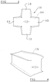
- a "blank" 11 of fabric is illustrated from which an air-bag may be fabricated.
- the blank is of generally cruciform shape having a substantially square central region 12 with four orthogonally extending arms 13. Each arm tapers slightly towards its free end.
- the "blank" of Figure 3 may be folded to form a bag having the configuration of Figure 4 by folding the four arms 13 to extend parallel with each other in a direction which is perpendicular to the plane of the square central portion 12. The free edges of the arms will then abut each other and stitching may be provided, in the positions indicated by the dotted lines 14 of Figure 3, to constitute seams 15 as shown in Figure 4.
- the bag is thus formed of a unitary sheet of fabric but edges of the fabric are joined together by securing seams 15.
- the seams 15 are of general type illustrated in Figure 2, the edge portions of the fabric between the stitching and the edge of the fabric not contributing to the integrity of the bag.
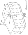
- the tuck 16 brings together, at either end, regions 18,19 of the projecting edge portions of the fabric of the bag which project beyond the securing seams 15. These abutting regions 18 and 19 are joined together by a zig-zag "tear seam” 20. It can be seen, from Figure 5, that four “tear seams” of this type will be provided in the bag. The “tear seams” maintain the “tucks” and limit the internal volume of the bag.
- the "tear seams” When the air-bag is inflated and thus has the condition illustrated in Figure 5, the "tear seams" will initially be placed under slight tension. As the pressure in the bag continues to rise the “tear seams” will rip or tear, thus releasing the tucks 16,17 and effectively increasing the interior volume of the bag. The “tear seams” are so located that inflation of the bag is controlled so that the bag does not hit the passenger or driver to be protected by the bag.
- the "tear seams” will rip or tear, either by the thread forming the stitching breaking, or by the fabric tearing in the region of the stitching or near the stitching. It can be seen that even if the ripping of the "tear seams" causes apertures to form within the material of the bag, these apertures will only be in that part of the material of the bag between the securing seam 15 and the edge of the fabric, in other words in a position corresponding to the edge portions 8 and 9 of Figure 2, and this will not influence the integrity of the bag.
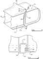
- Figure 6 illustrates an alternate form of bag, similar to that shown in Figure 5, which comprises two side sheets 21,22 which each correspond with one of the arms 13 of the blank of Figure 3, and a single top, end and bottom sheet 23 which corresponds to the two other arms and the central square region of the blank of Figure 3.
- top sheet is stitched to each side sheet along the top of the bag, across the end of the bag and along the bottom of the bag, in the orientation illustrated in Figure 6.
- the bag of Figure 6 may be inverted (or turned inside-out) so that the tucks 16,17 are on the interior of the bag, as shown in Figure 7. This provides the bag with a smoother exterior and minimises the risk of injury to a person who impinges the bag.
- the tearable means is formed of a piece of fabric that extends across and retains a tuck formed in the bag.
- the bag is provided with two opposed tucks 16,17 of the type described above.
- tuck 16 the regions 18 and 19 of the projecting edge portions of the fabric of the bag which extend beyond the securing seams 15 in the region of the tuck are joined together by a piece of fabric 24 which is formed integrally with the region 19, and which has a free end portion which is stitched or otherwise secured to the region 18.
- the piece of fabric 24 is provided with a weakened central region defined by a notch 25 formed in one side of the piece of fabric.
- FIG. 9 provides a sectional view of the arrangement, illustrating how the additional piece of fabric 24 is stitched to the region 18 by a double seam 26.
- Figure 10 illustrates the edge of the piece of fabric used to form the upper part of the bag illustrated in Figure 8, showing the additional piece of fabric 24 with the notch 25.
- the piece of fabric 24 forming the tearable means is formed integrally with the fabric forming the rest of the bag
- the fabric forming the tearable means could comprise a separate element of fabric 27 as illustrated in Figure 11, the extra piece of fabric again having a notch 25 and being secured to the abutting regions 18 and 19 by appropriate seams, one of which, 28, is illustrated schematically.
- the piece of fabric that forms the tearable means has been shown as having one notch formed in one side, the piece of fabric could have two opposed notches formed in the opposed side edges, or could have a central aperture, preferably of "diamond" shape.
- a bag having a tearable means as illustrated in Figures 8 to 10 or as illustrated in Figure 11 could again be turned inside-out, so as to resemble the bag shown in Figure 7.
Landscapes
- Engineering & Computer Science (AREA)
- Mechanical Engineering (AREA)
- Air Bags (AREA)
Description
- THE PRESENT INVENTION relates to an air-bag arrangement and more particularly relates to an air-bag arrangement adapted to protect a driver or passenger in a motor vehicle such as a motor car.
- It has been proposed to provide an air-bag in a motor car positioned in front of the driver or in front of a passenger of the motor car, the bag being adapted to inflate in the event that an accident arises. The bag thus provides a "cushion" for the driver or passenger.
- The design of air-bags is now very sophisticated, and the bag is adapted to be inflated when the driver or passenger is thrown forwardly within the motor vehicle.
- Reference may be made to EP-A-0,344,422 which discloses a bag in which parts of the bag are folded together to form a "tuck" by stitching, the stitching forming a "tear seam". The main purpose of this is to control the way that the bag is inflated. Thus the "tear seam" effectively controls the speed of inflation or the direction in which the bag expands during inflation, so that the bag, when it is inflated, does not hit the driver or passenger with a significant force. The "tear seam" is designed to tear or rip, enabling the "tuck" to open out effectively increasing the interior volume of the bag.
- One disadvantage of the system of EP-A-O,344,422 is that the "tear seam" comprises stitching which passes through part of the bag which forms the boundary between the interior of the bag and the exterior of the bag. When the "tear seam" tears or rips, it is to be understood that either the thread forming the stitching can break or the fabric in the region of the seam can tear. It is possible that the fabric will tear along the line of the stitching, since the fabric will have been pierced by the needle when the stitches have been put in place, and the fabric may thus have been punctured or weakened in the line of the stitching. However, it is also possible that the fabric adjacent the actual stitching may tear or rip. In any event, it is quite possible that the fabric of the bag may become damaged. If the fabric of the bag is damaged and is apertured, the bag may deflate in an undesirable manner, and the bag will then not provide the desired cushioning effect.
- The present invention seeks to provide an improved air-bag arrangement.
- According to this invention there is provided an inflatable bag adapted to protect a driver or passenger in a motor vehicle, the bag being formed from one or more elements of fabric, portions of the fabric being secured together by seams, the bag being provided with one or more tearable means designed to break when the bag is exposed to an internal pressure in excess of a predetermined pressure, the tearable means controlling the way the bag is inflated, the interior volume of the bag being greater when the tearable means have broken wherein there are areas of fabric adjacent the seams which areas do not, if apertured or damaged, affect the integrity of the bag, said tearable means being present in said areas of fabric.
- It is to be understood that the tearable means may comprise a stitched seam where either the thread forming the seam or the fabric through which the thread passes is adapted to tear, or may comprise a specific portion of fabric provided in the region of a stitched seam which is intended to tear when an appropriate force is applied to the fabric.
- Conveniently, the said areas of fabric are under tension when the bag is inflated and define one or more tucks in side walls of the bag.
- In one embodiment, the or each tearable means comprises a stitched seam provided adjacent an edge of elements of fabric secured together by the securing seams, there being edge portions of the fabric extending between the securing seams and the edge of the fabric, the "tear seam" being located in said edge portions.
- In an alternative embodiment of the invention the or each tearable means is defined by a piece of fabric that extends across and retains a tuck formed in the bag. The piece of fabric may be integral with the fabric of the bag or the piece of fabric may be separate from the fabric of the bag. Preferably the piece of fabric has a weakened portion to facilitate tearing of the fabric, and the weakened part may be constituted by one or more notches formed in the edges of the piece of fabric.
- Advantageously, at least one side of the bag is folded to form a tuck so that regions of edge portions of the fabric forming that side of the bag, that is to say portions of the fabric between the edges of the fabric and securing seams provided adjacent the edges of the side of the bag securing that side of the bag to other sides of the bag, are folded to lie adjacent each other, said regions being secured together by said tear seams.
- In one embodiment, the said portions of the fabric which do not determine the integrity of the bag are located on the exterior of the bag. Alternatively, the portions of the bag which do not affect the integrity of the bag are located on the interior of the bag.
- In one embodiment, the bag is made of a single sheet of fabric of generally cruciform shape.
- Alternatively, the bag is made of three sheets of fabric, two sheets forming opposed side walls, and a further sheet forming a top wall, an end and a bottom wall of the bag, in one orientation.
- In order that the invention may be more readily understood, and so that further features thereof may be appreciated, the invention will now be described, by way of example, with reference to the accompanying drawings, in which:
- FIGURE 1 is a view of a conventional seam as provided in an air-bag,
- FIGURE 2 is a view of an alternative form of seam,
- FIGURE 3 is a plan view of a "blank" which can be used for forming a bag,
- FIGURE 4 is a view of a bag being made from the blank of Figure 3,
- FIGURE 5 is a view of the bag of Figure 4 when completed,
- FIGURE 6 is a perspective view of another form of bag,
- FIGURE 7 is a view of the bag of Figure 6 when turned inside out,
- FIGURE 8 is a view, corresponding to Figure 5, illustrating a modified embodiment of the invention,
- FIGURE 9 is a cross-sectional view of Figure 8 taken on the line IX-IX,
- FIGURE 10 is a plan view of part of the fabric forming the bag of Figures 8 and 9, and
- FIGURE 11 is a view of part of a further modified bag in accordance with the invention, with parts thereof cut-away for the sake of clarity of illustration.
- Referring initially to Figure 1 of the drawings, a conventional "interlocked" seam for an air-bag or the like is illustrated. A first sheet of
fabric 1 has a terminal edge thereof folded back on itself to form a U-shapedchannel 2. A second sheet offabric 3, to be connected to the first sheet, has a terminal edge thereof folded back to form aU-shaped channel 4. - The folded back edges are then inter-nested so that the two
channels stitching 5 is placed in position extending through four thicknesses of the fabric. Thus, thestitching 5 extends through the parts of thefabric sheet 1 that form both side walls of thechannel 2 and through parts of thefabric sheet 3 that form both side walls of thechannel 4. - It is to be noted that a seam of this type does not present any exposed free edges of the cloth or fabric.
- Figure 2 illustrates an alternate form of seam where two sheets of
fabric 6,7 are located withedge portions stitching 10 is located in position joining theedge portions edge portions - It is to be appreciated that if an air-bag is made utilising seams of the type illustrated in Figure 2, the
edge portions fabric sheets 6 and 7. Consequently, if any tearing or ripping occurs to theedge portions fabric sheets 6 and 7 as illustrated in Figure 2. - Referring now to Figure 3, a "blank" 11 of fabric is illustrated from which an air-bag may be fabricated. The blank is of generally cruciform shape having a substantially square
central region 12 with four orthogonally extendingarms 13. Each arm tapers slightly towards its free end. - The "blank" of Figure 3 may be folded to form a bag having the configuration of Figure 4 by folding the four
arms 13 to extend parallel with each other in a direction which is perpendicular to the plane of the squarecentral portion 12. The free edges of the arms will then abut each other and stitching may be provided, in the positions indicated by thedotted lines 14 of Figure 3, to constituteseams 15 as shown in Figure 4. The bag is thus formed of a unitary sheet of fabric but edges of the fabric are joined together by securingseams 15. Theseams 15 are of general type illustrated in Figure 2, the edge portions of the fabric between the stitching and the edge of the fabric not contributing to the integrity of the bag. - Referring now to Figure 5 of the accompanying drawings, it can be seen that the bag of Figure 4 has been compressed axially, thus forming a
tuck - It can be seen that the
tuck 16 brings together, at either end,regions securing seams 15. Theseabutting regions - When the air-bag is inflated and thus has the condition illustrated in Figure 5, the "tear seams" will initially be placed under slight tension. As the pressure in the bag continues to rise the "tear seams" will rip or tear, thus releasing the
tucks - The "tear seams" will rip or tear, either by the thread forming the stitching breaking, or by the fabric tearing in the region of the stitching or near the stitching. It can be seen that even if the ripping of the "tear seams" causes apertures to form within the material of the bag, these apertures will only be in that part of the material of the bag between the securing
seam 15 and the edge of the fabric, in other words in a position corresponding to theedge portions - Figure 6 illustrates an alternate form of bag, similar to that shown in Figure 5, which comprises two
side sheets arms 13 of the blank of Figure 3, and a single top, end andbottom sheet 23 which corresponds to the two other arms and the central square region of the blank of Figure 3. - It can be seen that the top sheet is stitched to each side sheet along the top of the bag, across the end of the bag and along the bottom of the bag, in the orientation illustrated in Figure 6.
- The remaining features of the bag are as described with reference to the bag of Figure 5.
- The bag of Figure 6 may be inverted (or turned inside-out) so that the
tucks - It has been found that various types of stitching may be used to form the "tear seams" 20 as described above. Whilst reference has been made to "zig-zag" "tear seams" various forms of stitching may be used comprising one or more straight seams extending parallel with the edge of the fabric, one or more straight seams extending parallel but perpendicularly to the edge of the fabric, or a "castellated" seam. It has been found that these stitched seams do not operate in a totally consistent manner in that the maximum load necessary to cause a stitched seam of this type to tear as compared with the average load, may be significantly greater than the average load. Typically, the maximum load is of the order of two times the average load.
- It has been found that more consistent results can be obtained when the tearable means is formed of a piece of fabric that extends across and retains a tuck formed in the bag.
- Referring now to Figure 8, which illustrates a modified embodiment of the bag illustrated in Figure 6 (the same reference numerals apply to the same parts), the bag is provided with two
opposed tucks regions seams 15 in the region of the tuck are joined together by a piece offabric 24 which is formed integrally with theregion 19, and which has a free end portion which is stitched or otherwise secured to theregion 18. The piece offabric 24 is provided with a weakened central region defined by anotch 25 formed in one side of the piece of fabric. The arrangement is such that when the bag is inflated and subjected to an internal pressure in excess of a predetermined limit, the piece offabric 24 will tear transversely, the tear commencing at thenotch 25. The tear will follow the warp or the weft of the fabric. It has been found that providing a tearable means of this type gives more consistent results in that, in a batch of bags, the maximum force necessary to cause the tearable means to be actuated is very close to the average force for the batch. It can be seen that thetuck 17 is provided with a similar tearable means. Figure 9 provides a sectional view of the arrangement, illustrating how the additional piece offabric 24 is stitched to theregion 18 by adouble seam 26. Figure 10 illustrates the edge of the piece of fabric used to form the upper part of the bag illustrated in Figure 8, showing the additional piece offabric 24 with thenotch 25. - It is to be appreciated that whilst, in the embodiment described with reference to Figures 8 to 10, the piece of
fabric 24 forming the tearable means is formed integrally with the fabric forming the rest of the bag, the fabric forming the tearable means could comprise a separate element offabric 27 as illustrated in Figure 11, the extra piece of fabric again having anotch 25 and being secured to the abuttingregions - Whilst the piece of fabric that forms the tearable means has been shown as having one notch formed in one side, the piece of fabric could have two opposed notches formed in the opposed side edges, or could have a central aperture, preferably of "diamond" shape.
- A bag having a tearable means as illustrated in Figures 8 to 10 or as illustrated in Figure 11 could again be turned inside-out, so as to resemble the bag shown in Figure 7.
- The features disclosed in the foregoing description, in the following Claims and/or in the accompanying drawings may, both separately and in any combination thereof, be material for realising the invention in diverse forms thereof.
Claims (10)
- An inflatable bag adapted to protect a driver or passenger in a motor vehicle, the bag being formed from one or more elements of fabric (12,13,21,22,23), portions of the fabric being secured together by seams (15), the bag being provided with one or more tearable means (20,24,27) designed to break when the bag is exposed to an internal pressure in excess of a predetermined pressure, the tearable means (20,24,27) controlling the way the bag is inflated, the interior volume of the bag being greater when the tearable means (20,24,27) have broken, characterised in that there are areas (18,19) of fabric adjacent the seams(15) which areas do not, if apertured or damaged, affect the integrity of the bag, said tearable means (20,24,27) being present in said areas (18,19) of fabric.
- A bag according to Claim 1 wherein the said areas (18,19) of fabric are under tension when the bag is inflated and define one or more tucks (16,17) in side walls of the bag.
- A bag according to Claim 1 or 2 wherein the or each of said tearable means comprises a stitched seam (20) provided adjacent an edge of elements of fabric secured together by the securing seams (15), there being edge portions of the fabric extending between the securing seams (15) and the edge of the fabric, the seam being located in said edge portions (18,19).
- A bag according to Claim 1 or 2 wherein the or each tearable means is defined by a piece of fabric (24,27) that extends across and retains a tuck (16,17) formed in the bag.
- A bag according to Claim 4 wherein the piece of fabric (24) is integral with the fabric of the bag.
- A bag according to Claim 4 wherein the piece of fabric (27) is separate from the fabric of the bag.
- A bag according to any one of Claims 4 to 6 wherein the piece of fabric (24,27) has a weakened portion to facilitate tearing of the fabric.
- A bag according to Claim 7 wherein the piece of fabric (24,27) has one or more notches (25) formed in the edges thereof to constitute said weakened part.
- A bag according to any one of the preceding Claims wherein at least one side of the bag is folded to form a tuck (16,17) so that regions (18,19) of edge portions of the fabric forming that side of the bag, that is to say portions of the fabric between the edges of the fabric and securing seams (15) provided adjacent the edges of the side of the bag securing that side of the bag to other sides of the bag, are folded to lie adjacent each other, said regions (18,19) being secured together by said tearable means (20,24,27).
- A bag according to any one of Claims 1 to 9 wherein the areas of the bag which do not affect the integrity of the bag are located on the interior of the bag.
Priority Applications (2)
| Application Number | Priority Date | Filing Date | Title |
|---|---|---|---|
| GB9315698A GB2271322B (en) | 1992-10-09 | 1993-07-29 | Improvements in or relating to an air-bag arrangement |
| US08/133,386 US5568938A (en) | 1992-10-09 | 1993-10-08 | Air-bag arrangement |
Applications Claiming Priority (2)
| Application Number | Priority Date | Filing Date | Title |
|---|---|---|---|
| GB9201792A GB2263668B (en) | 1992-01-28 | 1992-01-28 | Improvements in or relating to an air bag arrangement |
| GB9201792 | 1992-01-28 |
Publications (2)
| Publication Number | Publication Date |
|---|---|
| EP0553542A1 EP0553542A1 (en) | 1993-08-04 |
| EP0553542B1 true EP0553542B1 (en) | 1996-05-22 |
Family
ID=10709386
Family Applications (1)
| Application Number | Title | Priority Date | Filing Date |
|---|---|---|---|
| EP19920309219 Expired - Lifetime EP0553542B1 (en) | 1992-01-28 | 1992-10-09 | Improvements in or relating to an air-bag arrangement |
Country Status (4)
| Country | Link |
|---|---|
| EP (1) | EP0553542B1 (en) |
| DE (1) | DE69210985T2 (en) |
| ES (1) | ES2087457T3 (en) |
| GB (1) | GB2263668B (en) |
Cited By (1)
| Publication number | Priority date | Publication date | Assignee | Title |
|---|---|---|---|---|
| DE19643052A1 (en) * | 1996-10-18 | 1997-09-04 | Daimler Benz Ag | Airbag for vehicles with fold(s) |
Families Citing this family (18)
| Publication number | Priority date | Publication date | Assignee | Title |
|---|---|---|---|---|
| US5482317A (en) * | 1993-06-28 | 1996-01-09 | Sandia Corporation | Structurally efficient inflatable protective device |
| WO1995006574A1 (en) * | 1993-08-31 | 1995-03-09 | Alliedsignal Inc. | Air bag with improved tear stitch pattern |
| JPH07125592A (en) * | 1993-11-05 | 1995-05-16 | Takata Kk | Air bag |
| JP3115477B2 (en) * | 1994-06-09 | 2000-12-04 | トヨタ自動車株式会社 | Method of manufacturing airbag bag |
| US5454595A (en) * | 1994-09-08 | 1995-10-03 | Morton International, Inc. | Hidden volume cushion |
| US5520414A (en) * | 1994-11-23 | 1996-05-28 | Milliken Research Corporation | Inflatable restraint cushion |
| US5511821A (en) * | 1994-12-21 | 1996-04-30 | Morton International, Inc. | Vehicle restraint system cushion with sacrificial tear seam |
| DE29510775U1 (en) * | 1995-07-03 | 1995-09-14 | Trw Repa Gmbh, 73553 Alfdorf | Airbag on the passenger side |
| JPH09323605A (en) * | 1996-03-27 | 1997-12-16 | Morton Internatl Inc | Method of protecting occupant within cabin of automobile and method of folding air bag cushion |
| US5823567A (en) * | 1996-07-03 | 1998-10-20 | Precision Fabrics Group, Inc. | Folded inflatable protective device and method for making same |
| GB2318767B (en) * | 1996-10-15 | 2000-11-15 | Autoliv Dev | Improvements in or relating to a folded side impact airbag |
| DE29804239U1 (en) | 1998-03-10 | 1998-08-20 | TRW Occupant Restraint Systems GmbH & Co. KG, 73553 Alfdorf | Airbag for a vehicle occupant restraint system |
| WO2003066388A1 (en) * | 2002-02-07 | 2003-08-14 | Dalphi Metal España, S.A. | Airbag comprising tearable support band |
| GB2386586B (en) | 2002-03-19 | 2005-06-08 | Autoliv Dev | Improvements in or relating to an air-bag |
| DE10224967B4 (en) * | 2002-06-05 | 2007-10-04 | Webasto Ag | Roof module for a vehicle |
| GB2389819A (en) * | 2002-06-18 | 2003-12-24 | Autoliv Dev | Airbag formed from a single element of fabric |
| DE102006024599A1 (en) * | 2006-05-26 | 2007-11-29 | Autoliv Development Ab | Airbag arrangement has sudden drop between first and second levels from passenger's viewpoint in fully expanded state and head section associated with first level |
| CN103874607B (en) * | 2011-10-14 | 2018-04-06 | Tk控股公司 | Air bag module |
Family Cites Families (5)
| Publication number | Priority date | Publication date | Assignee | Title |
|---|---|---|---|---|
| US3810654A (en) * | 1972-05-05 | 1974-05-14 | Gen Motors Corp | Occupant restraint cushion assembly and method of manufacture |
| JPS515730A (en) * | 1974-07-02 | 1976-01-17 | Nissan Motor | Eabatsugusochino batsuguseizohoho |
| DE3544248C1 (en) * | 1985-12-14 | 1987-01-29 | Audi Ag | Inflatable impact cushion |
| DE3818185C1 (en) * | 1988-05-28 | 1989-08-17 | Daimler-Benz Aktiengesellschaft, 7000 Stuttgart, De | |
| US5022675A (en) * | 1989-11-30 | 1991-06-11 | Allied-Signal Inc. | Air bag and folding technique |
-
1992
- 1992-01-28 GB GB9201792A patent/GB2263668B/en not_active Expired - Fee Related
- 1992-10-09 DE DE1992610985 patent/DE69210985T2/en not_active Expired - Fee Related
- 1992-10-09 EP EP19920309219 patent/EP0553542B1/en not_active Expired - Lifetime
- 1992-10-09 ES ES92309219T patent/ES2087457T3/en not_active Expired - Lifetime
Cited By (1)
| Publication number | Priority date | Publication date | Assignee | Title |
|---|---|---|---|---|
| DE19643052A1 (en) * | 1996-10-18 | 1997-09-04 | Daimler Benz Ag | Airbag for vehicles with fold(s) |
Also Published As
| Publication number | Publication date |
|---|---|
| GB9201792D0 (en) | 1992-03-11 |
| DE69210985T2 (en) | 1996-10-31 |
| EP0553542A1 (en) | 1993-08-04 |
| DE69210985D1 (en) | 1996-06-27 |
| ES2087457T3 (en) | 1996-07-16 |
| GB2263668A (en) | 1993-08-04 |
| GB2263668B (en) | 1995-02-01 |
Similar Documents
| Publication | Publication Date | Title |
|---|---|---|
| EP0553542B1 (en) | Improvements in or relating to an air-bag arrangement | |
| US5454595A (en) | Hidden volume cushion | |
| US8096578B2 (en) | Knee airbag | |
| US7695013B2 (en) | Deployment control device for airbag | |
| JP5295820B2 (en) | Air bag and air bag device | |
| JP4132259B2 (en) | Airbag built-in seat | |
| US5732973A (en) | Tuck folded air bag | |
| MXPA02009364A (en) | Air bag tether construction. | |
| US5511821A (en) | Vehicle restraint system cushion with sacrificial tear seam | |
| GB2397805A (en) | Air-bag with expansion panel | |
| US5568938A (en) | Air-bag arrangement | |
| EP2174843B1 (en) | Air-bag | |
| EP1636072B1 (en) | An air-bag | |
| JP2668332B2 (en) | Airbag device for passenger seat | |
| JPH07329694A (en) | Internal pressure adjusting device for air bag | |
| JPH10181503A (en) | Side air bag device | |
| JPH07329685A (en) | Air bag | |
| JP3677607B2 (en) | Vehicle seat structure | |
| JP5309156B2 (en) | Inflatable airbag | |
| JP2000142290A (en) | Vehicular air bag | |
| JP3596103B2 (en) | Passenger airbag | |
| JPH0820305A (en) | Air bag for vehicle | |
| EP1481854A1 (en) | Airbag comprising tearable support band | |
| JP4052611B2 (en) | Airbag body of airbag device | |
| JP7089754B2 (en) | Seat Cover |
Legal Events
| Date | Code | Title | Description |
|---|---|---|---|
| PUAI | Public reference made under article 153(3) epc to a published international application that has entered the european phase |
Free format text: ORIGINAL CODE: 0009012 |
|
| AK | Designated contracting states |
Kind code of ref document: A1 Designated state(s): DE ES FR GB |
|
| 17P | Request for examination filed |
Effective date: 19940121 |
|
| 17Q | First examination report despatched |
Effective date: 19950331 |
|
| RBV | Designated contracting states (corrected) |
Designated state(s): DE ES FR |
|
| GRAH | Despatch of communication of intention to grant a patent |
Free format text: ORIGINAL CODE: EPIDOS IGRA |
|
| GRAA | (expected) grant |
Free format text: ORIGINAL CODE: 0009210 |
|
| AK | Designated contracting states |
Kind code of ref document: B1 Designated state(s): DE ES FR |
|
| REG | Reference to a national code |
Ref country code: ES Ref legal event code: BA2A Ref document number: 2087457 Country of ref document: ES Kind code of ref document: T3 |
|
| REF | Corresponds to: |
Ref document number: 69210985 Country of ref document: DE Date of ref document: 19960627 |
|
| REG | Reference to a national code |
Ref country code: ES Ref legal event code: FG2A Ref document number: 2087457 Country of ref document: ES Kind code of ref document: T3 |
|
| ET | Fr: translation filed | ||
| PLBE | No opposition filed within time limit |
Free format text: ORIGINAL CODE: 0009261 |
|
| STAA | Information on the status of an ep patent application or granted ep patent |
Free format text: STATUS: NO OPPOSITION FILED WITHIN TIME LIMIT |
|
| 26N | No opposition filed | ||
| PGFP | Annual fee paid to national office [announced via postgrant information from national office to epo] |
Ref country code: ES Payment date: 20031126 Year of fee payment: 12 |
|
| PG25 | Lapsed in a contracting state [announced via postgrant information from national office to epo] |
Ref country code: ES Free format text: LAPSE BECAUSE OF NON-PAYMENT OF DUE FEES Effective date: 20041011 |
|
| PGFP | Annual fee paid to national office [announced via postgrant information from national office to epo] |
Ref country code: DE Payment date: 20051006 Year of fee payment: 14 |
|
| PGFP | Annual fee paid to national office [announced via postgrant information from national office to epo] |
Ref country code: FR Payment date: 20051010 Year of fee payment: 14 |
|
| REG | Reference to a national code |
Ref country code: ES Ref legal event code: FD2A Effective date: 20041011 |
|
| PG25 | Lapsed in a contracting state [announced via postgrant information from national office to epo] |
Ref country code: DE Free format text: LAPSE BECAUSE OF NON-PAYMENT OF DUE FEES Effective date: 20070501 |
|
| REG | Reference to a national code |
Ref country code: FR Ref legal event code: ST Effective date: 20070629 |
|
| PG25 | Lapsed in a contracting state [announced via postgrant information from national office to epo] |
Ref country code: FR Free format text: LAPSE BECAUSE OF NON-PAYMENT OF DUE FEES Effective date: 20061031 |