EP0553540B1 - Container having means for stacking on three different levels - Google Patents
Container having means for stacking on three different levels Download PDFInfo
- Publication number
- EP0553540B1 EP0553540B1 EP19920309115 EP92309115A EP0553540B1 EP 0553540 B1 EP0553540 B1 EP 0553540B1 EP 19920309115 EP19920309115 EP 19920309115 EP 92309115 A EP92309115 A EP 92309115A EP 0553540 B1 EP0553540 B1 EP 0553540B1
- Authority
- EP
- European Patent Office
- Prior art keywords
- container
- base
- support member
- state
- support
- Prior art date
- Legal status (The legal status is an assumption and is not a legal conclusion. Google has not performed a legal analysis and makes no representation as to the accuracy of the status listed.)
- Expired - Lifetime
Links
Images


Classifications
-
- B—PERFORMING OPERATIONS; TRANSPORTING
- B65—CONVEYING; PACKING; STORING; HANDLING THIN OR FILAMENTARY MATERIAL
- B65D—CONTAINERS FOR STORAGE OR TRANSPORT OF ARTICLES OR MATERIALS, e.g. BAGS, BARRELS, BOTTLES, BOXES, CANS, CARTONS, CRATES, DRUMS, JARS, TANKS, HOPPERS, FORWARDING CONTAINERS; ACCESSORIES, CLOSURES, OR FITTINGS THEREFOR; PACKAGING ELEMENTS; PACKAGES
- B65D21/00—Nestable, stackable or joinable containers; Containers of variable capacity
- B65D21/02—Containers specially shaped, or provided with fittings or attachments, to facilitate nesting, stacking, or joining together
- B65D21/06—Containers specially shaped, or provided with fittings or attachments, to facilitate nesting, stacking, or joining together with movable parts adapted to be placed in alternative positions for nesting the containers when empty and for stacking them when full
- B65D21/062—Containers specially shaped, or provided with fittings or attachments, to facilitate nesting, stacking, or joining together with movable parts adapted to be placed in alternative positions for nesting the containers when empty and for stacking them when full the movable parts being attached or integral and displaceable into a position overlying the top of the container, e.g. bails, corner plates
Definitions
- the present invention relates to an open topped container which can be assembled with several similar containers to form a vertical column in either a fully nested condition (where an overlying container is partly received within the container which underlies it so that bases of adjacent nested containers are relatively close together) or a stacked condition (in which adjacent containers in the column are supported so that their bases are relatively widely spaced). More particularly the invention concerns open topped containers having pivotally mounted U-shaped bars which are associated with the open top to extend between opposed side walls of the containers and be adjustable to one position in which they provide clearance through the open top for a similar container to be received for nesting and another position in which the bars are located and retained to co-operate with recesses in the base of an overlying container and provide support for that container in column stacking.
- An example of an open topped container capable of nesting or column stacking by use of pivotal bars is disclosed in G.B. A-1,444,356.
- containers which are capable of both nesting and column stacking are well known in the art. Principally these are that the containers when empty can be assembled as a vertical column in a fully nested condition to minimise the space occupied by the containers (as is desirable for storage and transport) and the containers when full can be stacked as a vertical column (which is again convenient for storage and transport) while the support bars ensure that the contents of a container will not be compressed or otherwise damaged by overlying containers. With known open topped containers of this latter type it is frequently found that with several containers stacked as a column, the column occupies an amount of storage space which is not justified by the contents of the containers.
- containers of the kind discussed have been proposed which provide the option of three levels of assembly in forming a vertical column, namely the aforementioned fully nested and stacked conditions and an intermediate nested condition in which adjacent containers in the column are supported so that their bases are spaced at a distance less than that of the stacked condition and greater than that of the fully nested condition.
- Examples of containers which provide the facility for three level column assembly as aforementioned are disclosed in Patent Specifications GB-A-2,104,486 (preamble of claim 1), US-A-4.573,577, GB-A-2,067,167 and CA-A-1,128.878.
- the optional variations of the three level assembly are achieved by pivotally adjusting the U-shaped support bars to predetermined positions so that such bars on an underlying container of two adjacent containers in a column, are positioned either to unimpede the accomodation of the overlying container in the underlying container to permit the fully nested condition or to support the overlying container in either of the stacked or intermediate nested conditions.
- the support is achieved with the U-shaped bars of the underlying container co-operating with channels in the base of the overlying container which channels are selected from an array of such channels in the base.
- an open topped container comprising a base, opposed side walls extending upwardly from the base and two base support means located one towards each end of the side walls and extending between the side walls; each base support means comprising a "U" shaped support member having a back portion which extends between the opposed side walls and leg portions which are mounted for pivotal movement on the side walls so that the support member can be pivotted for effecting selective adjustment of the base support means; the two base support means being selectively pivotal to a first position of adjustment in which the back portions of the support members are out of overlying relationship with the base to provide clearance whereby, in forming a vertical column of similar containers, a first of two such containers can be received from the open top of the second container having its base support means in the first position for the first container to be nested in a deep condition in the second container, to a second position of adjustment in which back portions of the base support means are supported in overlying relationship with the base whereby in forming said vertical column of similar containers the first container can be column
- the base and walls will usually be moulded in plastics with plastics or metal forming the pivotted base support means.
- the support members of the base support means will usually be in the form of U-shaped bars, rods or bar-like components.
- the container will be of generally oblong rectangular parallelopipedon shape with the side walls extending over the longer extent and with a base support means provided towards each end of the container so that the support means provide symmetrical support to the base of an overlying container in a stack.
- each base support means comprises an upper support member and a lower support member which are pivotally mounted on the side walls to be independently pivotal between a first state in which they are supported to overlie the base and a second state in which they are out of overlying relationship with the base and which upper and lower members are arranged so that said first position of adjustment is provided when both the upper and lower support members are in their second state, said second position of adjustment is provided when the upper support member is in its first state for that support member to support the base of a second container in column stacking, and said third position of adjustment is provided when the upper support member is in its second state and the lower support member is in its first state for the lower support member to support the base of a second container in shallow nesting.
- each base support means comprises a single support member which is pivotally mounted on the side walls and selectively pivotal to a high state corresponding to said second position of adjustment, a low state corresponding to the third position of adjustment and a third state corresponding to the first position of adjustment.
- the single support member is maintained in its third state or its high state by abutment with a wall of the container and is movable passed the abutment by displacement of the pivotal mountings of the support member to permit the support member to be adjustable between the third state and the low state through the high state.
- the pivotal mounting of the support member is displaceable relative to the side walls to permit that member to be movable between at least two of its first, second and third positions.
- the displacement of the pivotal mounting of the support member relative to the side walls is preferably effected by the ends of the support member being slidable in respective tracks on the side walls, such tracks conveniently being formed as slots in the side walls.
- the ends of the support member are slidable in tracks it is preferred that in each of the high, low and third states of that member its ends are at the same position in the tracks and at such position the tracks may include seatings within which the respective ends of the support member are received in a stable, relatively firm, manner when the support member is in each of its high, low and third states.
- cam faces are arranged to promote location of the support member in the third state during displacement of the support member from the low state to the third state - this is to facilitate simple and convenient readjustment of the container from a shallow nesting condition to a deep nesting condition.
- the side walls of the container may present the aforementioned cam faces remote from the tracks and with which cam faces the leg portions of the support bar slidably abut to provide the required promotion of the support bar to its high, low or third state.
- the leg portions of the support bar may present cam faces which slidably abut the side walls of the container (possibly abutting predetermined cam faces presented by those side walls) remote from the tracks to provide the required promotion of the support component to its high, low or third state.
- the support member can conveniently be formed as a plastics moulding and this is particularly advantageous where leg portions of that member are of a predetermined shape for edges thereof to present the aforementioned cam faces for abutment against the side walls.
- the container will have one or more end walls which extend between the opposed side walls.
- the single support member can conveniently abut an adjacent end wall.
- the support members of the base support means are supported to be maintained in the second or third positions of adjustment by abutment of the support members against shoulders or seatings presented by upstanding walls of the container.
- the container of the present invention will have its upstanding walls appropriately tapered, splayed and/or stepped as is well known in the art to provide a required configuration for several similar containers to be nested in a vertical column.
- the containers 1 have a generally flat oblong rectangular base 2 upstanding from which are opposed longer side walls 3 and 4 and opposed end walls 5 and 6 which extend between the side walls. Usually the base and walls are formed as a plastics moulding.
- the walls 3 to 6 are stepped to diverge outwardly as they approach and form a rectangular open top 7 within which can be located the base and lower portions of the walls of a similar overlying container (indicated at 1A) to provide nesting in the erection of the vertical column in known manner.
- Extending between the opposed side walls 3 and 4 are two base support means indicated at 8 and 9 which are located, one each, towards the longitudinally opposite ends of the container.
- the base support means 8 and 9 are constructed in an identical manner to each other and serve a similar purpose, for convenience therefore the means 9 need only be described.
- the base support means 9 consists of two metal or plastics support rods or bars 10 and 11 each of which has a straight back portion 12 and leg portions 13.
- the support bar 10 has its leg portions 13 presenting bosses which are pivotally mounted at 14 in the respective side walls 3 and 4 so that the bar 10 can pivot about an axis extending through the pivots 14 for its back portion 12 to be positioned in a rebate 15 in the top edge of the end wall (as shown at the lefthand end of Figure 1) or to be accommodated in seatings 16 in the side walls so that its back portion 10 extends across the open top 7 (as shown at the righthand end of the container in Figure 1) and directly overlies a rebate or channel 2' presented on the underside of the base 2 (see Figure 2).
- the support bar 11 is located within the container 1 at a lower level than the bar 10 and has the ends of its legs 13 presenting bosses which are pivotally mounted at 17 in the side walls 3 and 4.
- the bar 11 can be pivotted optionally so that its back portion 12 will lie on an upwardly directed internal shoulder 18 of the adjacent end wall (as shown for the bar 11 at the lefthand end of the container in Figure 1) or to be seated in rebates 19 so that the back portion 12 of the bar 11 extends across the width of the container parallel to and spaced from the end walls (as shown at the righthand end of the container in Figure 1) and directly overlies the rebate or channel 2' presented on the base 2 (see Figure 2).
- a second similar container can be lowered through the open top of the underlying container 1 so that its base and lower parts of its walls are received within the underlying container until the base of the overlying container stands on the back portions 12 of the two support bars 11.
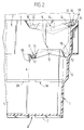
- a second similar container 1A (as indicated in Figure 2) can be received within the open top of the container 1 and lowered to effect nesting in a deep condition.
- the base indicated at 2A of the upper container is at the closest spacing from the base 2 of the underlying container and therefore the underlying container 1 has less space available for the storage of contents than the space which is available when the upper container is supported in a relatively shallow nested condition.
- the maximum depth to which the upper container may be received within the underlying container may be determined in conventional manner, for example by an external flange or rib 1C on the upper container 1A abutting the upper rim around the open top of the underlying container or by the base of the upper container abutting an internal shoulder presented by the walls of the underlying container.
- the upstanding walls 3 to 6 of the container are tapered or splayed to converge as they approach the base 2.
- the walls are shown with a stepped configuration to provide appropriate clearance for nesting and also to ensure that there is adequate space available for the back portion 12 of the support bar 11 (as shown ghosted at 12 in Figure 2) to be positioned out of overlying relationship with the base 2.
- the stepped wall and support bar arrangement shown in Figure 2 two containers can be assembled as a vertical column in any one of a deep nested, shallow nested or column stacked conditions with approximately one third of the depth of the container walls separating one condition from another.
- each of the base support means 8 and 9 is in the form of a single U-shaped support rod or bar 20 having a straight back portion 21 which extends between the opposed side walls 3 and 4 of the container and leg portions 22.
- the base support means 9 has been shown and it will be appreciated that the base support means 8 towards the opposite end of the container will have a similar but mirror image arrangement to that shown.
- the opposite end of the support bar is arranged on the side wall 4 in a similar manner to that shown on the side wall 3.
- the leg portions 22 of the support bar 20 have bosses 23 by which they are pivotally mounted on the respective side walls for rotation about a common axis through the two pivots so that the bar can be selectively pivotted.
- the support bar 20 has the bosses 23 of its leg portions 22 pivotally and slidably mounted in tracks provided by slots 60 in the opposed side walls 3 and 4.
- the slots 60 are elongated substantially parallel with the base 2 and the pivotal bosses 23 at the ends of the leg portions 22 are displaceable along the slots 60.
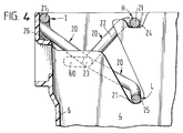
- Figure 4 illustrates the three positions into which the support bar 20 can be pivotally and optionally adjusted; for convenience the support bar 20 is shown in complete lines in each of the three positions and they consist of a high state H in which the back portion 21 overlies the base 2, a low state L in which the back portion 21 overlies the base 2 but is nearer to the base 2 than when in the high state H and a third state I in which the back portion 21 is out of overlying relationship with the base 2.
- the support bar 20 is supported in its high state H by abutment of the bar on a seating 24 extending from a channel 24A in which the leg portions 22 of the bar are conveniently accommodated in the high state.
- the support bar 20 is supported in its low state L by an upwardly directed shoulder or seating 25 in the side wall.
- the support bar 20 is retained in its intermediate state I by abutment with a stop 26 in the form of a small flange or shoulder on the end wall 6.
- a second similar container 1A can be column stacked with its base supported on the back portions 21 of the bars as shown.
- a second similar container 1A can be received within the open top 7 in a deep nested condition similar to that previously discussed in connection with the first embodiment.
- a second similar container 1A can be received within the open top 7 of an underlying container so that the base 2A of the overlying container stands on the back portions 21 of the support bars. Consequently the two containers will be in a shallow nested condition similar to that previously discussed in connection with the first embodiment.
- the support bar 20 is displaceable between its third state I and the low state L effectively through its high state H.
- the support bar 20 can be displaced from the state I selectively into either the high state H or the low state L for column stacking or shallow nesting respectively.
- the support bar back portion 21 is supported on the seating 24 of the side walls.
- the legs 22 can be pivotted upwardly for the back portion 21 to clear the seatings 24 and the pivotal mountings 23 displaced along the slot 60 sufficiently for the back portion 21 to move out of overlying engagement with the seatings 24 so that the support bar can be allowed to fall on to the seating 25 and adopt the low state L.
- the leg portions 22 of the support bar are shown cranked in Figure 4 and also the slot 60 is shown substantially straight and parallel to the base of the container but it will be appreciated that these characteristics can be varied as appropriate for a particular design of container.
- channels or rebates 2' are provided on the underside face of the base 2 to receive and provide firm engagement with the back portions 21 on the support bars of a similar underlying container on which the base may sit.
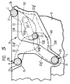
- Figure 5 shows a modification of the arrangement in Figure 4 whereby the pivotal bosses 23 are slidably mounted in L-shaped slots 60A.
- An end 60B of the L-shaped slot 60A provides a seating within which the respective boss 23 is located firmly when the support bar 20 is in each of its H, I or L states.
- the support bar 20 can be pivotted directly between its H and I states.
- the legs 22 are cranked or otherwise shaped to present cam surfaces which react against appropriately profiled cam surfaces presented by the side walls 3 and 4 so that the aforementioned reaction provides guidance for the bar back portion 21 under manually applied pressure to move towards and into the seating 25 of the L state or onto the stop 26 of the I state as the case may be.
- the support bar 20 it is considered particularly advantageous for the support bar 20 to be manually displaceable easily and automatically during pivotal movement from its L state to its I state; the reason for this is that following use of several containers having their support bars in the L state for shallow nesting, the bars of the containers may be readjusted simply, quickly and by inexperienced handlers from the L state to the I state for deep nesting of the empty containers as a stack to facilitate their transport or storage.
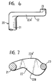
- the legs 22 of the support bar 21 are in the form of plate-like sections from which extend the bosses 23 and the bar back portion 21 as shown in Figure 6 and which sections are in the form of cam plates as indicated in Figure 7 so that the side edges thereof present cam faces of predetermined profile which are intended to facilitate and promote displacement of the support bar during its pivotal movement from the L state to the I state.
- the cam plate-like section of each leg 22 presents a smoothly curved, generally convex rear cam face 22A' and a smoothly curved, generally convex, front cam face 22B.
- cam faces 22A' and 22B are intended to react with cam faces presented on the respective side wall of the container to facilitate a simple and smooth transition of the support bar during its movement from state L to state I.
- the front cam face 22B abuts and slides over a cam face 101 presented by the container side wall and the reaction between the cam faces 22B and 101 causes the boss 23 to be lifted smoothly from its seating 60B in the slot 60A and that boss to be displaced along the slot 60A to a position indicated at 23' in Figure 5.
- the support bar or rod 20 will usually be formed of metal or plastics.
- the support bar shown in Figure 5 is particularly suitable for moulding in plastics, possibly with glass reinforcement, for convenience of economically forming the cam shape plate-like sections for the legs 22.
- the support bar 20 is maintained in its high state H by abutment with the side walls of the container in the seating 24 and is movable passed the seating 24 by displacement of the support bar relative to the seating as the bosses 23 slide along the slots 60 and 60A to permit the support bar to be adjusted between the state I and the low state L, in effect by pivotal movement through the high state H.
- the pivotal bosses 23 are located in the same position in their respective slots.
Landscapes
- Engineering & Computer Science (AREA)
- Mechanical Engineering (AREA)
- Stackable Containers (AREA)
Description
- The present invention relates to an open topped container which can be assembled with several similar containers to form a vertical column in either a fully nested condition (where an overlying container is partly received within the container which underlies it so that bases of adjacent nested containers are relatively close together) or a stacked condition (in which adjacent containers in the column are supported so that their bases are relatively widely spaced). More particularly the invention concerns open topped containers having pivotally mounted U-shaped bars which are associated with the open top to extend between opposed side walls of the containers and be adjustable to one position in which they provide clearance through the open top for a similar container to be received for nesting and another position in which the bars are located and retained to co-operate with recesses in the base of an overlying container and provide support for that container in column stacking. An example of an open topped container capable of nesting or column stacking by use of pivotal bars is disclosed in G.B. A-1,444,356.
- The advantages of containers which are capable of both nesting and column stacking are well known in the art. Principally these are that the containers when empty can be assembled as a vertical column in a fully nested condition to minimise the space occupied by the containers (as is desirable for storage and transport) and the containers when full can be stacked as a vertical column (which is again convenient for storage and transport) while the support bars ensure that the contents of a container will not be compressed or otherwise damaged by overlying containers. With known open topped containers of this latter type it is frequently found that with several containers stacked as a column, the column occupies an amount of storage space which is not justified by the contents of the containers. To alleviate this disadvantage containers of the kind discussed have been proposed which provide the option of three levels of assembly in forming a vertical column, namely the aforementioned fully nested and stacked conditions and an intermediate nested condition in which adjacent containers in the column are supported so that their bases are spaced at a distance less than that of the stacked condition and greater than that of the fully nested condition. Examples of containers which provide the facility for three level column assembly as aforementioned are disclosed in Patent Specifications GB-A-2,104,486 (preamble of claim 1), US-A-4.573,577, GB-A-2,067,167 and CA-A-1,128.878. In each of these examples the optional variations of the three level assembly are achieved by pivotally adjusting the U-shaped support bars to predetermined positions so that such bars on an underlying container of two adjacent containers in a column, are positioned either to unimpede the accomodation of the overlying container in the underlying container to permit the fully nested condition or to support the overlying container in either of the stacked or intermediate nested conditions. In these latter conditions the support is achieved with the U-shaped bars of the underlying container co-operating with channels in the base of the overlying container which channels are selected from an array of such channels in the base. It is an object of the present invention to provide an open topped container which provides a three level assembly facility in forming a column as aforementioned and which is an improvement over known such containers (the most relevant of which is believed to be that disclosed in GB-A-2,104,486).
- According to the present invention there is provided an open topped container comprising a base, opposed side walls extending upwardly from the base and two base support means located one towards each end of the side walls and extending between the side walls; each base support means comprising a "U" shaped support member having a back portion which extends between the opposed side walls and leg portions which are mounted for pivotal movement on the side walls so that the support member can be pivotted for effecting selective adjustment of the base support means; the two base support means being selectively pivotal to a first position of adjustment in which the back portions of the support members are out of overlying relationship with the base to provide clearance whereby, in forming a vertical column of similar containers, a first of two such containers can be received from the open top of the second container having its base support means in the first position for the first container to be nested in a deep condition in the second container, to a second position of adjustment in which back portions of the base support means are supported in overlying relationship with the base whereby in forming said vertical column of similar containers the first container can be column stacked with its base supported on said back portions of the base support means of the second container in the second position, and to a third position of adjustment in which back portions of the base support means are supported in overlying relationship with the base whereby in forming said vertical column of similar containers the first container can be nested in a shallow condition in the second container with the base of the first container supported on said back portions of the base support means of the second container in the third position; the base of the container being provided with channels or rebates arranged so that in both said shallow nested condition and said column stacked condition, back portions of the base support means of the second container co-operate with said channels or rebates in the base of the first container; in said shallow nested condition the base of the first container is spaced from the base of the second container to a greater extent than said spacing when the two containers are in the deep nested condition and to a lesser extent than said spacing when the two containers are column stacked, and in said deep nested, shallow nested and column stacked conditions the first container has its base substantially parallel with the base of the second container CHARACTERISED IN THAT the positions of said back portions of the base support means when in the second position of adjustment directly overlie the positions of said back portions of the respective base support means when in the third position of adjustment and directly overlie channels or rebates in the base.
- As is usual for containers of the kind to which the present invention applies, the base and walls will usually be moulded in plastics with plastics or metal forming the pivotted base support means. The support members of the base support means will usually be in the form of U-shaped bars, rods or bar-like components.
- Typically the container will be of generally oblong rectangular parallelopipedon shape with the side walls extending over the longer extent and with a base support means provided towards each end of the container so that the support means provide symmetrical support to the base of an overlying container in a stack.
- In a preferred embodiment each base support means comprises an upper support member and a lower support member which are pivotally mounted on the side walls to be independently pivotal between a first state in which they are supported to overlie the base and a second state in which they are out of overlying relationship with the base and which upper and lower members are arranged so that said first position of adjustment is provided when both the upper and lower support members are in their second state, said second position of adjustment is provided when the upper support member is in its first state for that support member to support the base of a second container in column stacking, and said third position of adjustment is provided when the upper support member is in its second state and the lower support member is in its first state for the lower support member to support the base of a second container in shallow nesting.
- In a second embodiment each base support means comprises a single support member which is pivotally mounted on the side walls and selectively pivotal to a high state corresponding to said second position of adjustment, a low state corresponding to the third position of adjustment and a third state corresponding to the first position of adjustment. Preferably the single support member is maintained in its third state or its high state by abutment with a wall of the container and is movable passed the abutment by displacement of the pivotal mountings of the support member to permit the support member to be adjustable between the third state and the low state through the high state.
- In a preferred arrangement of the second embodiment the pivotal mounting of the support member is displaceable relative to the side walls to permit that member to be movable between at least two of its first, second and third positions. The displacement of the pivotal mounting of the support member relative to the side walls is preferably effected by the ends of the support member being slidable in respective tracks on the side walls, such tracks conveniently being formed as slots in the side walls. Where the ends of the support member are slidable in tracks it is preferred that in each of the high, low and third states of that member its ends are at the same position in the tracks and at such position the tracks may include seatings within which the respective ends of the support member are received in a stable, relatively firm, manner when the support member is in each of its high, low and third states. It is also preferred to facilitate adjustment of the support member from one state to another that during such adjustment the support member abuts the side walls through cam faces at positions remote from the aforementioned tracks and during sliding movement of the ends of the support member in the respective tracks to a predetermined position, said abutment through the cam faces (possibly assisted by guidance from the ends of the support member in their respective tracks) promotes the support member to become located in at least one of its high, low or third states. Desirably the cam faces are arranged to promote location of the support member in the third state during displacement of the support member from the low state to the third state - this is to facilitate simple and convenient readjustment of the container from a shallow nesting condition to a deep nesting condition. By having the support member in the form of the U-shaped bar or rod with its leg portions pivotally mounted on the side walls of the container and the ends of those leg portions displaceable along the aforementioned tracks, the side walls of the container may present the aforementioned cam faces remote from the tracks and with which cam faces the leg portions of the support bar slidably abut to provide the required promotion of the support bar to its high, low or third state. Alternatively, or in addition, the leg portions of the support bar may present cam faces which slidably abut the side walls of the container (possibly abutting predetermined cam faces presented by those side walls) remote from the tracks to provide the required promotion of the support component to its high, low or third state. The support member can conveniently be formed as a plastics moulding and this is particularly advantageous where leg portions of that member are of a predetermined shape for edges thereof to present the aforementioned cam faces for abutment against the side walls.
- Usually the container will have one or more end walls which extend between the opposed side walls. In the aforementioned third state, the single support member can conveniently abut an adjacent end wall.
- Preferably the support members of the base support means are supported to be maintained in the second or third positions of adjustment by abutment of the support members against shoulders or seatings presented by upstanding walls of the container.
- It will be appreciated that the container of the present invention will have its upstanding walls appropriately tapered, splayed and/or stepped as is well known in the art to provide a required configuration for several similar containers to be nested in a vertical column.
- Two embodiments of an open topped container constructed in accordance with the present invention will now be described, by way of example only, with reference to the accompanying illustrative drawings in which:-
- Figure 1 is a perspective view of a first embodiment in which the base support means is provided by two support bars at each end of the container;
- Figure 2 is a scrap section taken on the line II - II of Figure 1;
- Figure 3 is a perspective view showing part of the second embodiment in which the base support means is provided by a single support bar at each end of the container;
- Figure 4 is a scrap section of the container in Figure 3 schematically illustrating the adjustment available for the single support bar at each end of the container;
- Figure 5 is a scrap section of a container similar to that shown in Figure 4 and illustrates a modification for the base support means;
- Figure 6 is a plan view of an end part length of the support bar in the base support means of Figure 5, and
- Figure 7 is a side elevation of a leg on the support bar of Figure 6.
- The
containers 1 have a generally flat oblongrectangular base 2 upstanding from which are opposedlonger side walls 3 and 4 and opposedend walls open top 7 within which can be located the base and lower portions of the walls of a similar overlying container (indicated at 1A) to provide nesting in the erection of the vertical column in known manner. Extending between theopposed side walls 3 and 4 are two base support means indicated at 8 and 9 which are located, one each, towards the longitudinally opposite ends of the container. The base support means 8 and 9 are constructed in an identical manner to each other and serve a similar purpose, for convenience therefore themeans 9 need only be described. - The base support means 9 consists of two metal or plastics support rods or
bars straight back portion 12 andleg portions 13. Thesupport bar 10 has itsleg portions 13 presenting bosses which are pivotally mounted at 14 in therespective side walls 3 and 4 so that thebar 10 can pivot about an axis extending through thepivots 14 for itsback portion 12 to be positioned in arebate 15 in the top edge of the end wall (as shown at the lefthand end of Figure 1) or to be accommodated inseatings 16 in the side walls so that itsback portion 10 extends across the open top 7 (as shown at the righthand end of the container in Figure 1) and directly overlies a rebate or channel 2' presented on the underside of the base 2 (see Figure 2). - The
support bar 11 is located within thecontainer 1 at a lower level than thebar 10 and has the ends of itslegs 13 presenting bosses which are pivotally mounted at 17 in theside walls 3 and 4. Thebar 11 can be pivotted optionally so that itsback portion 12 will lie on an upwardly directedinternal shoulder 18 of the adjacent end wall (as shown for thebar 11 at the lefthand end of the container in Figure 1) or to be seated inrebates 19 so that theback portion 12 of thebar 11 extends across the width of the container parallel to and spaced from the end walls (as shown at the righthand end of the container in Figure 1) and directly overlies the rebate or channel 2' presented on the base 2 (see Figure 2). - With the two
support bars 10 in their respectively associatedseating 16 and the twosupport bars 11 seated in their respectively associatedrebates 19 it will be seen, particularly from Figure 2 that theback portions 12 will directly overlie the rebate or channel 2' in thebase 2. Alternatively when thesupport bars 10 are pivotted for theirback portions 12 to be seated in their respectively associatedrebates 15 and when the back portions of thebars 11 are supported on their respectively associatedshoulders 18, it will be seen from Figure 2 that the back portions of the respective support bars are out of overlying relationship with thebase 2. - It will be apparent from Figures 1 and 2 that when the two
support bars 10 are pivotted so that they are supported on theseatings 16 presented by upwardly directed shoulders on the side walls, theirback portions 12 extend across the open top of the container in the general plane of that top opening so that a secondsimilar container 1A can be column stacked with itsbase 2 standing on the back portions of thesupport bars 10. Such column stacking permits a major part of the container to be available for receiving goods to be stored or transported whilst alleviating the likelihood of such goods being damaged or crushed by loading from an overlying container in the erection of a column of containers. - By pivotting the
support bars 10 so that they are accommodated in therebates 15 and pivotting the twosupport bars 11 so that they are supported in theseatings 19 for theirback portions 12 to overlie thebase 2 as shown in Figure 2, a second similar container can be lowered through the open top of theunderlying container 1 so that its base and lower parts of its walls are received within the underlying container until the base of the overlying container stands on theback portions 12 of the twosupport bars 11. In this latter condition the space available for the storage of goods within the underlying container between thebase 2 of that container and the base of the overlying container which is supported by thebars 11 will be less than the previous storage space available for the two containers when column stacked; nevertheless this reduction in space may be adequate for certain purposes and may alleviate unnecessary waste of overall storage space which could result from column stacking. - If both the
support bars 10 and thesupport bars 11 are pivotted so that theirback portions 12 are out of overlying relationship with thebase 2 with such back portions resting on theappropriate rebates 15 andshoulders 18, a secondsimilar container 1A (as indicated in Figure 2) can be received within the open top of thecontainer 1 and lowered to effect nesting in a deep condition. In this latter condition the base indicated at 2A of the upper container is at the closest spacing from thebase 2 of the underlying container and therefore theunderlying container 1 has less space available for the storage of contents than the space which is available when the upper container is supported in a relatively shallow nested condition. The maximum depth to which the upper container may be received within the underlying container may be determined in conventional manner, for example by an external flange or rib 1C on theupper container 1A abutting the upper rim around the open top of the underlying container or by the base of the upper container abutting an internal shoulder presented by the walls of the underlying container. - To provide the required nesting the upstanding walls 3 to 6 of the container are tapered or splayed to converge as they approach the
base 2. In the embodiment shown in Figures 1 and 2 the walls are shown with a stepped configuration to provide appropriate clearance for nesting and also to ensure that there is adequate space available for theback portion 12 of the support bar 11 (as shown ghosted at 12 in Figure 2) to be positioned out of overlying relationship with thebase 2. With the stepped wall and support bar arrangement shown in Figure 2, two containers can be assembled as a vertical column in any one of a deep nested, shallow nested or column stacked conditions with approximately one third of the depth of the container walls separating one condition from another. - In the second embodiment, a basic arrangement of which is diagrammatically illustrated in Figures 3 and 4, each of the base support means 8 and 9 is in the form of a single U-shaped support rod or
bar 20 having astraight back portion 21 which extends between theopposed side walls 3 and 4 of the container andleg portions 22. For convenience in Figures 3 to 5 only the base support means 9 has been shown and it will be appreciated that the base support means 8 towards the opposite end of the container will have a similar but mirror image arrangement to that shown. Also only one end of thesupport bar 20 has been shown and it will be appreciated that the opposite end of the support bar is arranged on theside wall 4 in a similar manner to that shown on the side wall 3. Theleg portions 22 of thesupport bar 20 havebosses 23 by which they are pivotally mounted on the respective side walls for rotation about a common axis through the two pivots so that the bar can be selectively pivotted. Thesupport bar 20 has thebosses 23 of itsleg portions 22 pivotally and slidably mounted in tracks provided byslots 60 in theopposed side walls 3 and 4. Theslots 60 are elongated substantially parallel with thebase 2 and thepivotal bosses 23 at the ends of theleg portions 22 are displaceable along theslots 60. Figure 4 illustrates the three positions into which thesupport bar 20 can be pivotally and optionally adjusted; for convenience thesupport bar 20 is shown in complete lines in each of the three positions and they consist of a high state H in which theback portion 21 overlies thebase 2, a low state L in which theback portion 21 overlies thebase 2 but is nearer to thebase 2 than when in the high state H and a third state I in which theback portion 21 is out of overlying relationship with thebase 2. Thesupport bar 20 is supported in its high state H by abutment of the bar on aseating 24 extending from a channel 24A in which theleg portions 22 of the bar are conveniently accommodated in the high state. Thesupport bar 20 is supported in its low state L by an upwardly directed shoulder orseating 25 in the side wall. Thesupport bar 20 is retained in its intermediate state I by abutment with astop 26 in the form of a small flange or shoulder on theend wall 6. - With the
support bar 20 in its high state H and with the two support bars so positioned, a secondsimilar container 1A can be column stacked with its base supported on theback portions 21 of the bars as shown. - With the
support bar 20 pivotted to its intermediate state I so that itsback portion 21 abuts thestop 26 to be out of overlying relationship with thebase 2, a secondsimilar container 1A can be received within the open top 7 in a deep nested condition similar to that previously discussed in connection with the first embodiment. - With both
support bars 20 pivotted into their low state L for theback portion 21 to be supported by theseatings 25 to overlie thebase 2, a secondsimilar container 1A can be received within theopen top 7 of an underlying container so that thebase 2A of the overlying container stands on theback portions 21 of the support bars. Consequently the two containers will be in a shallow nested condition similar to that previously discussed in connection with the first embodiment. - During its pivotal movement the
support bar 20 is displaceable between its third state I and the low state L effectively through its high state H. This is best appreciated from Figure 4 where it will be seen that in its third state I thesupport bar 20 abuts thesupport shoulder 26 on the end wall to permit deep nesting. By pivotal movement, thesupport bar 20 can be displaced from the state I selectively into either the high state H or the low state L for column stacking or shallow nesting respectively. In the high state H the support bar backportion 21 is supported on theseating 24 of the side walls. To move the support bar from its high state H into its low state L, thelegs 22 can be pivotted upwardly for theback portion 21 to clear the seatings 24 and thepivotal mountings 23 displaced along theslot 60 sufficiently for theback portion 21 to move out of overlying engagement with theseatings 24 so that the support bar can be allowed to fall on to theseating 25 and adopt the low state L. Theleg portions 22 of the support bar are shown cranked in Figure 4 and also theslot 60 is shown substantially straight and parallel to the base of the container but it will be appreciated that these characteristics can be varied as appropriate for a particular design of container. From Figure 4 it will be seen that in each of the three states H, I and L of thesupport bar 20, theboss 23 is located at substantially the same position in theslot 60, usually seated at one end of that slot to facilitate its positioning. It will also be seen that in the state H the support bar backportion 21 directly overlies the position of thatportion 21 in the state L. - In accordance with conventional practice the channels or rebates 2' are provided on the underside face of the
base 2 to receive and provide firm engagement with theback portions 21 on the support bars of a similar underlying container on which the base may sit. - Figure 5 shows a modification of the arrangement in Figure 4 whereby the
pivotal bosses 23 are slidably mounted in L-shapedslots 60A. An end 60B of the L-shapedslot 60A provides a seating within which therespective boss 23 is located firmly when thesupport bar 20 is in each of its H, I or L states. When thebosses 23 are in the respective seatings 60B of the container side walls, thesupport bar 20 can be pivotted directly between its H and I states. To effect pivotal movement of the support bar from either its H or I state to its L state, or from its L state to either its H or I state, it is necessary for thebosses 23 to be displaced temporarily and reciprocated from their seatings 60B, along therespective slots 60A and then back to their seatings 60B. To facilitate displacement of the support bar during its movement between the L state and the I state, thelegs 22 are cranked or otherwise shaped to present cam surfaces which react against appropriately profiled cam surfaces presented by theside walls 3 and 4 so that the aforementioned reaction provides guidance for the bar backportion 21 under manually applied pressure to move towards and into theseating 25 of the L state or onto thestop 26 of the I state as the case may be. It is considered particularly advantageous for thesupport bar 20 to be manually displaceable easily and automatically during pivotal movement from its L state to its I state; the reason for this is that following use of several containers having their support bars in the L state for shallow nesting, the bars of the containers may be readjusted simply, quickly and by inexperienced handlers from the L state to the I state for deep nesting of the empty containers as a stack to facilitate their transport or storage. With this in mind, thelegs 22 of thesupport bar 21 are in the form of plate-like sections from which extend thebosses 23 and the bar backportion 21 as shown in Figure 6 and which sections are in the form of cam plates as indicated in Figure 7 so that the side edges thereof present cam faces of predetermined profile which are intended to facilitate and promote displacement of the support bar during its pivotal movement from the L state to the I state. More particularly the cam plate-like section of eachleg 22 presents a smoothly curved, generally convex rear cam face 22A' and a smoothly curved, generally convex,front cam face 22B. With the particular design of support bar mounting shown in Figure 5 both cam faces 22A' and 22B are intended to react with cam faces presented on the respective side wall of the container to facilitate a simple and smooth transition of the support bar during its movement from state L to state I. In Figure 5 as the bar backportion 21 is raised from theseating 25 in the L state during its movement towards the I state, thefront cam face 22B abuts and slides over acam face 101 presented by the container side wall and the reaction between the cam faces 22B and 101 causes theboss 23 to be lifted smoothly from its seating 60B in theslot 60A and that boss to be displaced along theslot 60A to a position indicated at 23' in Figure 5. In this latter position 23' there is adequate clearance of the bar backportion 21 from theseating 25 for the support bar to be pivotted clockwise in Figure 5 about the bosses 23' to approach the I state. As the cam shaped sections of thelegs 22 are rotated clockwise as aforementioned about the bosses 23', the rear cam faces 22A' of those sections move into abutment with and slide over acam face 102 presented by the respective side walls. During this latter sliding movement the reaction between the cam faces 22A' and 102 causes the respective bosses to be displaced smoothly from the position indicated at 23' towards and into the respective slot seatings 60B as the bar backportion 21 is promoted to engage on thestop 26 in its I state. - It will, of course, be appreciated that in Figure 5 various positions for the support bar legs, bar back portion and bosses have been indicated in ghost form or solid lines and that the
slot 60A and cam faces presented by the side walls of the container have been illustrated in ghost form as considered most convenient and appropriate for descriptive purposes. - As previously mentioned, the support bar or
rod 20 will usually be formed of metal or plastics. The support bar shown in Figure 5 is particularly suitable for moulding in plastics, possibly with glass reinforcement, for convenience of economically forming the cam shape plate-like sections for thelegs 22. - In each of the base support arrangements shown in Figures 4 and 5 it will be seen that the
support bar 20 is maintained in its high state H by abutment with the side walls of the container in theseating 24 and is movable passed theseating 24 by displacement of the support bar relative to the seating as thebosses 23 slide along theslots pivotal bosses 23 are located in the same position in their respective slots.
Claims (16)
- An open topped container comprising a base (2), opposed side walls (3, 4) extending upwardly from the base (2) and two base support means (8, 9, 20) located one towards each end of the side walls and extending between the side walls (3, 4); each base support means comprising a "U" shaped support member (10, 11, 20) having a back portion (12, 21) which extends between the opposed side walls (3, 4) and leg portions (13, 22) which are mounted for pivotal movement on the side walls (3, 4) so that the support member (10, 11, 20) can be pivotted for effecting selective adjustment of the base support means (8, 9, 20); the two base support means (8, 9, 20) being selectively pivotal to a first position of adjustment (I) in which the back portions (12, 21) of the support members are out of overlying relationship with the base (2) to provide clearance whereby, in forming a vertical column of similar containers, a first (1A) of two such containers can be received through the open top (7) of the second container (1) having its base support means (8, 9, 20) in the first position (I) for the first container (1A) to be nested in a deep condition in the second container (1), to a second position of adjustment (H) in which back portions (12, 21) of the base support means (8, 9, 20) are supported in overlying relationship with the base (2) whereby in forming said vertical column of similar containers the first container (1A) can be column stacked with its base (2A) supported on said back portions (12, 21) of the base support means (8, 9, 20) of the second container (1) in the second position (H), and to a third position of adjustment (L) in which back portions (12, 21) of the base support means (8, 9, 20) are supported in overlying relationship with the base (2) whereby in forming said vertical column of similar containers the first container (1A) can be nested in a shallow condition in the second container (1) with the base (2A) of the first container (1A) supported on said back portions (12, 21) of the base support means (8, 9, 20) of the second container (1) in the third position (L); the base (2) of the container being provided with channels or rebates (2') arranged so that in both said shallow nested condition and said column stacked condition, back portions (12, 21) of the base support means (8, 9, 20) of the second container (1) co-operate with said channels or rebates (2') in the base (2A) of the first container (1A); in said shallow nested condition the base (2A) of the first container (1A) is spaced from the base (2) of the second container (1) to a greater extent than said spacing when the two containers (1 and 1A) are in the deep nested condition and to a lesser extent than said spacing when the two containers are column stacked, and in said deep nested, shallow nested and column stacked conditions the first container has its base (2A) substantially parallel with the base (2) of the second container CHARACTERISED IN THAT the positions of said back portions (12, 21) of the base support means when in the second position of adjustment (H) directly overlie the positions of said back portions (12, 21) of the respective base support means when in the third position of adjustment (L) and directly overlie channels or rebates (2') in the base (2).
- A container as claimed in claim 1 in which each base support means (8, 9) comprises an upper support member (10) and a lower support member (11) which are pivotally mounted (14, 17) on the walls (3, 4) of the container to be independently pivotal between a first state in which they are supported for their back portions (12) to overlie the base (2) and a second state in which their back portions (12) are out of overlying relationship with the base (2) and which upper and lower support members (10, 11) are arranged so that said first position of adjustment is provided when both said upper and lower support members (10, 11) of the two base support means are in their second state, said second position of adjustment is provided when the upper support member (10) of each base support means (8, 9) is in its first state for the back portion (12) of that support member (10) to support the base (2A) of the second container (1A) in column stacking, and said third position of adjustment is provided when, for each base support means the upper support member (10) is in its second state and the lower support member (11) is in its first state for the back portions (12) of the lower support members (11) to support the base (2A) of a second container (1A) in shallow nesting.
- A container as claimed in claim 1 in which each base support means comprises a single support member (20) pivotally mounted (23) on the opposed side walls (3, 4) and selectively pivotal to a high state (H) corresponding to said second position of adjustment, a low state (L) corresponding to said third position of adjustment and a third state (I) corresponding to said first position of adjustment.
- A container as claimed in claim 3 in which the single support member (20) is maintained in said high state (H) by abutment (24) with a wall (3, 4) of the container and is movable passed said abutment (24) by relative displacement between said abutment (24) and the support member to permit the support member (20) to be adjustable between the third state (I) and the low state (L) through the high state (H).
- A container as claimed in either claim 3 or claim 4 in which the pivotal mounting (23) of the support member (20) is displaceable relative to the side walls (3, 4) to permit said support member (20) to be movable between at least two of the first, second and third positions.
- A container as claimed in claim 5 in which ends (23) of the support member (20) are slidable in respective tracks (60) (preferably slots) in the side walls (3, 4) to permit said displacement.
- A container as claimed in claim 6 in which in each of said high, low and third states of the support member (20) said ends (23) of the support member (20) are at substantially the same position in the respective tracks (60).
- A container as claimed in either claim 6 or claim 7 in which each of said tracks (60) includes a seating (60B) within which the respective end (23) of the support member (20) is received when the support member is in each of its high, low and third states.
- A container as claimed in any one of claims 6 to 8 in which during adjustment of the support member (20) from one state to another state, said support member (20) abuts the side walls (3, 4) through cam faces (22A, 22B, 101) remote from said tracks (60) and during sliding movement of the ends (23) of the support member (20) in the respective tracks (60) to a predetermined position, said abutment through the cam faces (22A, 22B, 101) promotes the support member to become located in at least one of its high, low or third states.
- A container as claimed in claim 9 when appendant to either claim 7 or claim 8 in which said predetermined position is the said same position for the ends (23) of the support member (20) in the tracks (60) in each of the high, low and third states.
- A container as claimed in either claim 9 or claim 10 in which the side walls (3, 4) of the container present cam faces (101) remote from the tracks (60) and with which cam faces (101) the leg portions (22) of the support member (20) slidably abut to provide said promotion of the support member (20).
- A container as claimed in any one of claims 9 to 11 in which the leg portions (22) of the support member (20) present cam faces (22A', 22B) which slidably abut the side walls (3, 4) of the container remote from the tracks (60) to provide said promotion of the support member (20).
- A container as claimed in any one of claims 9 to 12 in which the cam faces (22A', 22B, 101) are arranged to promote location of the support member (20) in the third state (I) during displacement of the support member from the low state (L) to the third state (I).
- A container as claimed in any one of the preceding claims in which end walls (5, 6) are provided that extend between the opposed side walls (3, 4) and in their third states (I) (corresponding to said first position of adjustment) the support members (10, 11, 20) abut the end walls (5, 6).
- A container as claimed in any one of the preceding claims in which the base support means is supported to be maintained in its second and third positions (H, L) of adjustment by abutment on shoulders or seatings (16, 19, 24, 25) presented by walls (3, 4) of the container.
- A container as claimed in any one of the preceding claims in which each support member (10, 11, 20) comprises a plastics moulding.
Priority Applications (1)
| Application Number | Priority Date | Filing Date | Title |
|---|---|---|---|
| EP95114080A EP0697341B1 (en) | 1992-01-30 | 1992-10-07 | Container having means for stacking at three different levels |
Applications Claiming Priority (4)
| Application Number | Priority Date | Filing Date | Title |
|---|---|---|---|
| GB929201985A GB9201985D0 (en) | 1992-01-30 | 1992-01-30 | An open topped container |
| GB9201985 | 1992-01-30 | ||
| GB9202833A GB2263689B (en) | 1992-01-30 | 1992-02-11 | An open topped container |
| GB9202833 | 1992-02-11 |
Related Child Applications (2)
| Application Number | Title | Priority Date | Filing Date |
|---|---|---|---|
| EP95114080A Division EP0697341B1 (en) | 1992-01-30 | 1992-10-07 | Container having means for stacking at three different levels |
| EP95114080.5 Division-Into | 1992-10-07 |
Publications (2)
| Publication Number | Publication Date |
|---|---|
| EP0553540A1 EP0553540A1 (en) | 1993-08-04 |
| EP0553540B1 true EP0553540B1 (en) | 1996-03-27 |
Family
ID=26300231
Family Applications (1)
| Application Number | Title | Priority Date | Filing Date |
|---|---|---|---|
| EP19920309115 Expired - Lifetime EP0553540B1 (en) | 1992-01-30 | 1992-10-07 | Container having means for stacking on three different levels |
Country Status (3)
| Country | Link |
|---|---|
| EP (1) | EP0553540B1 (en) |
| DE (2) | DE69226659T2 (en) |
| GB (1) | GB2288593B (en) |
Families Citing this family (5)
| Publication number | Priority date | Publication date | Assignee | Title |
|---|---|---|---|---|
| GB2264102B (en) * | 1992-02-15 | 1996-09-04 | Mckechnie Uk Ltd | Container |
| GB2289881A (en) * | 1994-06-01 | 1995-12-06 | Richardson Limited | Cullet delivery container |
| GB2331980B (en) * | 1997-12-03 | 2002-03-20 | Mckechnie Uk Ltd | Load transfer for multiple-height stacking |
| GB2373239B (en) * | 2001-03-02 | 2004-10-06 | Mckechnie Invest Holdings | Container |
| GB2428424A (en) | 2005-07-16 | 2007-01-31 | Linpac Materials Handling Ltd | Stackable crate having a RF identification device |
Family Cites Families (6)
| Publication number | Priority date | Publication date | Assignee | Title |
|---|---|---|---|---|
| DE947147C (en) * | 1954-04-09 | 1956-08-09 | Fischer Eckert & Co | Stacking box with swiveling handles |
| US2765099A (en) * | 1955-05-31 | 1956-10-02 | James W Lively | Lug box |
| CA1125193A (en) * | 1979-12-13 | 1982-06-08 | Elsmer W. Kreeger | Three-level baler |
| US4573577A (en) * | 1980-02-08 | 1986-03-04 | Buckhorn Material Handling Group Inc. | Stackable container |
| CA1128878A (en) * | 1980-04-24 | 1982-08-03 | Phillips-Parkway Corporation | Three tier bread tray |
| US4391369A (en) * | 1981-08-31 | 1983-07-05 | Pinckney Molded Plastics, Inc. | Four-level stacking container |
-
1992
- 1992-02-11 GB GB9512133A patent/GB2288593B/en not_active Revoked
- 1992-10-07 DE DE1992626659 patent/DE69226659T2/en not_active Expired - Fee Related
- 1992-10-07 DE DE1992609483 patent/DE69209483T2/en not_active Expired - Fee Related
- 1992-10-07 EP EP19920309115 patent/EP0553540B1/en not_active Expired - Lifetime
Also Published As
| Publication number | Publication date |
|---|---|
| GB9512133D0 (en) | 1995-08-23 |
| DE69209483T2 (en) | 1996-11-28 |
| GB2288593A (en) | 1995-10-25 |
| DE69209483D1 (en) | 1996-05-02 |
| EP0553540A1 (en) | 1993-08-04 |
| DE69226659T2 (en) | 1999-05-06 |
| DE69226659D1 (en) | 1998-09-17 |
| GB2288593B (en) | 1996-01-03 |
Similar Documents
| Publication | Publication Date | Title |
|---|---|---|
| EP0697341A1 (en) | Container having means for stacking at three different levels | |
| US4391369A (en) | Four-level stacking container | |
| US5617953A (en) | Stackable/nestable containers | |
| US4378925A (en) | T-Bracket shelf assembly | |
| US4204658A (en) | Seat-supporting slides | |
| EP0764587B1 (en) | Multi-level nestable container | |
| EP0629558A1 (en) | Stackable container | |
| AU592381B2 (en) | Slide device for an automotive seat | |
| DE69426241T2 (en) | NEGOTIABLE DISPLAY RACK FOR BOTTLES | |
| US4647055A (en) | Carrier trolley, especially for customers of self-service stores | |
| US4577759A (en) | Three-level stacking container | |
| US6145664A (en) | Container | |
| EP2058238B1 (en) | Collapsible container | |
| US7063210B2 (en) | Stackable crate | |
| EP0681966A2 (en) | Stackable dispensing apparatus for wire reels | |
| US4750633A (en) | Storage and transportation case for shelf system | |
| GB2374859A (en) | Open topped container capable of nesting and stacking | |
| JPH11510085A (en) | Chair backrest height adjustment mechanism | |
| GB2067167A (en) | Stackable or nestable containers | |
| EP0553540A1 (en) | Container having means for stacking on three different levels | |
| GB2244972A (en) | Container with pivotally mounted handle | |
| GB2090227A (en) | Container | |
| EP1817239B1 (en) | Metallic lid for a can | |
| JPH06269331A (en) | Folding chair | |
| US6209963B1 (en) | Variable configuration mounting arrangement for a chair back support member |
Legal Events
| Date | Code | Title | Description |
|---|---|---|---|
| PUAI | Public reference made under article 153(3) epc to a published international application that has entered the european phase |
Free format text: ORIGINAL CODE: 0009012 |
|
| AK | Designated contracting states |
Kind code of ref document: A1 Designated state(s): DE FR GB NL SE |
|
| 17P | Request for examination filed |
Effective date: 19930621 |
|
| 17Q | First examination report despatched |
Effective date: 19941024 |
|
| GRAA | (expected) grant |
Free format text: ORIGINAL CODE: 0009210 |
|
| AK | Designated contracting states |
Kind code of ref document: B1 Designated state(s): DE FR GB NL SE |
|
| XX | Miscellaneous (additional remarks) |
Free format text: TEILANMELDUNG 95114080.5 EINGEREICHT AM 08/09/95. |
|
| ET | Fr: translation filed | ||
| REF | Corresponds to: |
Ref document number: 69209483 Country of ref document: DE Date of ref document: 19960502 |
|
| PLBE | No opposition filed within time limit |
Free format text: ORIGINAL CODE: 0009261 |
|
| 26N | No opposition filed | ||
| REG | Reference to a national code |
Ref country code: GB Ref legal event code: IF02 |
|
| REG | Reference to a national code |
Ref country code: GB Ref legal event code: 732E |
|
| REG | Reference to a national code |
Ref country code: GB Ref legal event code: 732E |
|
| NLS | Nl: assignments of ep-patents |
Owner name: LINPAC MATERIALS HANDLING LIMITED Effective date: 20050909 |
|
| REG | Reference to a national code |
Ref country code: FR Ref legal event code: TP |
|
| PGFP | Annual fee paid to national office [announced via postgrant information from national office to epo] |
Ref country code: NL Payment date: 20081005 Year of fee payment: 17 |
|
| PGFP | Annual fee paid to national office [announced via postgrant information from national office to epo] |
Ref country code: DE Payment date: 20081014 Year of fee payment: 17 |
|
| PGFP | Annual fee paid to national office [announced via postgrant information from national office to epo] |
Ref country code: FR Payment date: 20081014 Year of fee payment: 17 |
|
| REG | Reference to a national code |
Ref country code: FR Ref legal event code: CD |
|
| PGFP | Annual fee paid to national office [announced via postgrant information from national office to epo] |
Ref country code: SE Payment date: 20091007 Year of fee payment: 18 |
|
| REG | Reference to a national code |
Ref country code: GB Ref legal event code: 732E Free format text: REGISTERED BETWEEN 20100121 AND 20100127 |
|
| PGFP | Annual fee paid to national office [announced via postgrant information from national office to epo] |
Ref country code: GB Payment date: 20091007 Year of fee payment: 18 |
|
| REG | Reference to a national code |
Ref country code: NL Ref legal event code: V1 Effective date: 20100501 |
|
| REG | Reference to a national code |
Ref country code: FR Ref legal event code: ST Effective date: 20100630 |
|
| PG25 | Lapsed in a contracting state [announced via postgrant information from national office to epo] |
Ref country code: NL Free format text: LAPSE BECAUSE OF NON-PAYMENT OF DUE FEES Effective date: 20100501 Ref country code: FR Free format text: LAPSE BECAUSE OF NON-PAYMENT OF DUE FEES Effective date: 20091102 Ref country code: DE Free format text: LAPSE BECAUSE OF NON-PAYMENT OF DUE FEES Effective date: 20100501 |
|
| GBPC | Gb: european patent ceased through non-payment of renewal fee |
Effective date: 20101007 |
|
| PG25 | Lapsed in a contracting state [announced via postgrant information from national office to epo] |
Ref country code: GB Free format text: LAPSE BECAUSE OF NON-PAYMENT OF DUE FEES Effective date: 20101007 |
|
| PG25 | Lapsed in a contracting state [announced via postgrant information from national office to epo] |
Ref country code: SE Free format text: LAPSE BECAUSE OF NON-PAYMENT OF DUE FEES Effective date: 20101008 |