EP0553052B1 - Pistolet pour pulvérisation électrostatique de matériaux en poudre de diverses couleurs et caractéristiques - Google Patents
Pistolet pour pulvérisation électrostatique de matériaux en poudre de diverses couleurs et caractéristiques Download PDFInfo
- Publication number
- EP0553052B1 EP0553052B1 EP19930500006 EP93500006A EP0553052B1 EP 0553052 B1 EP0553052 B1 EP 0553052B1 EP 19930500006 EP19930500006 EP 19930500006 EP 93500006 A EP93500006 A EP 93500006A EP 0553052 B1 EP0553052 B1 EP 0553052B1
- Authority
- EP
- European Patent Office
- Prior art keywords
- gun
- nozzle
- passage
- rod
- electrode
- Prior art date
- Legal status (The legal status is an assumption and is not a legal conclusion. Google has not performed a legal analysis and makes no representation as to the accuracy of the status listed.)
- Expired - Lifetime
Links
- 239000000843 powder Substances 0.000 title claims description 15
- 238000007590 electrostatic spraying Methods 0.000 title claims description 5
- 239000003086 colorant Substances 0.000 title claims description 4
- 238000010168 coupling process Methods 0.000 claims description 12
- 238000005859 coupling reaction Methods 0.000 claims description 12
- 230000008878 coupling Effects 0.000 claims description 11
- 239000000203 mixture Substances 0.000 claims description 9
- 230000005686 electrostatic field Effects 0.000 claims description 7
- 239000000463 material Substances 0.000 claims description 4
- 238000005507 spraying Methods 0.000 claims description 4
- 239000006185 dispersion Substances 0.000 claims description 2
- 239000012530 fluid Substances 0.000 claims description 2
- 230000037431 insertion Effects 0.000 claims 2
- 238000003780 insertion Methods 0.000 claims 2
- 210000002445 nipple Anatomy 0.000 claims 1
- 239000007921 spray Substances 0.000 description 7
- 239000003973 paint Substances 0.000 description 6
- 239000004020 conductor Substances 0.000 description 4
- 239000000049 pigment Substances 0.000 description 4
- 238000004140 cleaning Methods 0.000 description 3
- 239000011248 coating agent Substances 0.000 description 2
- 238000000576 coating method Methods 0.000 description 2
- 238000010276 construction Methods 0.000 description 2
- 239000011810 insulating material Substances 0.000 description 2
- 230000015572 biosynthetic process Effects 0.000 description 1
- 230000003670 easy-to-clean Effects 0.000 description 1
- 239000012777 electrically insulating material Substances 0.000 description 1
- 210000004907 gland Anatomy 0.000 description 1
- 239000011521 glass Substances 0.000 description 1
- 238000012423 maintenance Methods 0.000 description 1
- 238000004519 manufacturing process Methods 0.000 description 1
- 239000002245 particle Substances 0.000 description 1
- 238000000926 separation method Methods 0.000 description 1
Images


Classifications
-
- B—PERFORMING OPERATIONS; TRANSPORTING
- B05—SPRAYING OR ATOMISING IN GENERAL; APPLYING FLUENT MATERIALS TO SURFACES, IN GENERAL
- B05B—SPRAYING APPARATUS; ATOMISING APPARATUS; NOZZLES
- B05B5/00—Electrostatic spraying apparatus; Spraying apparatus with means for charging the spray electrically; Apparatus for spraying liquids or other fluent materials by other electric means
- B05B5/025—Discharge apparatus, e.g. electrostatic spray guns
- B05B5/053—Arrangements for supplying power, e.g. charging power
- B05B5/0531—Power generators
-
- B—PERFORMING OPERATIONS; TRANSPORTING
- B05—SPRAYING OR ATOMISING IN GENERAL; APPLYING FLUENT MATERIALS TO SURFACES, IN GENERAL
- B05B—SPRAYING APPARATUS; ATOMISING APPARATUS; NOZZLES
- B05B5/00—Electrostatic spraying apparatus; Spraying apparatus with means for charging the spray electrically; Apparatus for spraying liquids or other fluent materials by other electric means
- B05B5/025—Discharge apparatus, e.g. electrostatic spray guns
- B05B5/03—Discharge apparatus, e.g. electrostatic spray guns characterised by the use of gas, e.g. electrostatically assisted pneumatic spraying
- B05B5/032—Discharge apparatus, e.g. electrostatic spray guns characterised by the use of gas, e.g. electrostatically assisted pneumatic spraying for spraying particulate materials
Definitions
- the present invention relates to a gun for electrostatic spraying of powder materials, in particular powder paint of various colors and characteristics, including powder of paint with metallic pigments for metallic paint applications.
- the proposed gun has been designed to simplify the tasks of color change as much as possible, by replacing, essentially, a single piece, which consists of a nozzle, at low cost, quick and very simple assembly and disassembly, associated with body of the gun barrel, having the particularity that this nozzle has a lateral opening for the arrangement, by means of a coupling piece or connection of the supply pipe of the powder-air mixture, which, thus penetrates directly to inside this nozzle and is electrostatically charged outside its axial passage duct.
- the air-powder mixture inlet and conduction pipe extends through the body of the spray gun, as can be seen in European patent EP- A-110 753, property of the depositor, which involves manufacturing the body of the complex gun, because it is necessary to build, inside, said conduit for circulation of the powder-air stream.
- the powder-air mixture when it passes through the body thereof, also circulates near the high voltage generator block, formed, conventionally, by a transformer and an oscillator associated with a voltage multiplier circuit, with which, if the powder contains metallic pigments, this proximity alters the conditions of electrostatic charge of this current of powder-air.
- Patent EP-A-164 837 which relates to an electrostatic spray gun, proposes an exchangeable barrel section, very complex and even, at its terminal section, near the spraying area, two sockets and differentiated conduits for the supply and circulation of pressurized air and fluidized powder paint also by pressurized air, respectively.
- Said terminal portion is, moreover, very bulky with a larger section than the rest of the barrel, which makes its use difficult in the case where it must be inserted into recesses or tubular bodies.
- US-A-5,056,720 describes a gun for electrostatic spray which can be electrically connected alternatively either to an internal high voltage generator or to an external high voltage source.
- the pistol comprises with constructive purposes two sections a first barrel section having means 95 for connecting it to a source of powder-air supply and to a source of supply of pressurized air, means for circulation and the dispersion of these two fluids, at least one electrode 108 of electrostatic charge and means for electrically connecting said electrode 108 to the high voltage power supply 20 and a second handle section attached.
- the barrel section 72 has various tubular portions 74, 76, 96 attached and thus it ends with a nozzle 96, fitted removably to a tubular portion 76 (with an inclined lateral opening 95), which in turn is attached stationary by a screw 80, at an end portion 78 which ends a section 74.
- the attachment of the part 76 requires a unique position of the powder-air supply tube which opens out inside said part.
- the object of the invention is the construction of a gun which can be applied to powder coating materials of various colors and characteristics, including conductive pigments (metallic paint), having the particularity, in addition to fulfilling conditions of simplicity helping the change of color, or, in the case of wear of the spraying section, of ensuring complete separation from the transport and circulation section of the powder-air mixture to the spraying and electrostatic charge zone, relative to the source of generation of said electrostatic charge.
- conductive pigments metallic paint
- Said high voltage generator block placed in the body of the gun and advantageously formed by several independent modules (see EP 110 753, cited) comprises in combination an oscillator and a transformer which convert a direct current of low voltage, supplied to the gun through a low voltage conductive cable, at a high frequency intermediate voltage, and a voltage multiplier circuit which, in turn, transforms said high frequency current into a high voltage direct current for application to one or more field generating electrodes electrostatic.
- the assembly proposes for this purpose the use of spray nozzles which can be replaced, very simple, easy to clean and of low cost, and therefore, easy to replace after a certain time of using them, or in the case of a color change (by providing, alternatively for cleaning, a nozzle for each color, for example), comprising a tubular body provided with a flange which abuts at the front end of the main body of the pistol and provided with a wick which extends it axially behind, and which fits, (or alternatively is screwed), into a housing of said pistol body, at the bottom of which there are means for the electrical connection to the high voltage source to generate the electrostatic field.
- the tubular body of the nozzle has a first conduit of wide passage and of uniform section, which largely surrounds a fixed central rod, deflector holder and finished in a frustoconical flare.
- a tubular section such as a screw connection, acting as connector for connection of the end of a flexible pipe for the circulation of the powder-air mixture to be sprayed which in this way has direct access to an area remote from the electrostatic charge generation block, and having free passage through this first, wide conduit, which is favored by the inclination of said lateral opening, the air-powder stream opening, at the end portion thereof, abutting against the deflector.
- An electrode for electrostatic charge extends through the center of the rod completely electrically insulated, or along the walls of the tubular body, also made of electrically insulating material, according to two possible embodiments of the object of the invention, and emerges outside the first nozzle duct in the electrostatic spraying area.
- the first conduit extends into a second axial conduit to said wick, with reduced passage, through which and adjusted under pressure is inserted the rear section of said insulating rod finished in a deflector body, also electrically insulating, which is arranged in front of the free, distal end of said wick of the tubular body, with the possibility of axial movement relative to the rod, to thus vary the amplitude of the spray field, by controlling the concentration of the electrostatic field produced by the electrode which is arranged near this zone, outside the body of the nozzle.
- Said nozzle is fixed to the main body of the gun, in a possible implementation, by means of a nut member which is screwed, in a threaded section existing at the front end of said gun body.
- the second conduit of the tubular body has a tubular sheath or cover, or a coating of its internal walls acting as a seal, when it is crossed with the deflector holder rod.
- the nozzle explained will be subdivided into two half-pieces that can be coupled by screwing them, one carrying the first duct with its lateral opening and the second , comprising the drill bit for the connection to the body of the gun with a blind axial hole or right through, for fixing the end of the deflector holder rod.
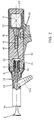
- Figure 1 is a side elevational view, with partial cross section of a gun, constructed according to the invention, and which includes as a characteristic part a nozzle which is illustrated in its mounting situation on the gun, and outside thereof ci, in two alternative implementations in FIGS. 1a and 1b, as well as coupling parts or fittings which couple to this nozzle, for connection of a pipe carrying the powder-air mixture.
- Figure 2 is a sectional view of a possible implementation of the object of the invention, in which the high voltage generator block is formed by several sub-modules, inserted in an axial housing in the barrel of the barrel of the gun, such as described in the Spanish utility model No. 264765 cited.
- Figure 3 illustrates an elevational view with partial section of the front section of the gun, with an alternative attachment of the deflector holder rod to the body of the nozzle.
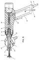
- FIG. 4 shows an elevation view of the gun, which includes a portion of the powder-air mixture supply pipe, connected to the body of the nozzle by a connection fitting, as described.
- Figure 5 is a side elevational view, with partial cross section of a gun, constructed according to a variant of the invention with a hollow rod and a duct for the supply of air to its interior
- the gun comprises a main body -30- made of electro-insulating material, which internally houses a set of elements linked together to generate the electrostatic field, supplied by a low voltage cable.
- -31- i.e. a low to high voltage transformer -12-, associated with an oscillator (included or not inside the handle -37-), the output of this transformer -12- remaining connected to a high voltage multiplier --10-, -11-.
- this transformer -12- forms a first module -32-, and the voltage multiplier a second module -19- mounted axially inside a tubular housing -18- of the pistol body, made of insulating material, so that they can be replaced separately, and remain delimited by a closing cover -25-, in accordance with the construction of the example of the utility model cited n o 264,765.
- a cover -13- also allows access to the transformer -12-.
- the multiplier -10-, - 11- is connected through a conductive cable -33- to a contact socket -8- (Fig.1), -20- (Fig.2), hence an electrode -1 -, -34- will take high-voltage current, said electrode being installed on the nozzle -4-via a conductor -1a- (Fig 1) axial to a rod -2- carrying a deflector -3- , both electrically insulating, or else via a conductor -23- (Fig 2) which extends through the walls of the nozzle -22-.
- the invention proposes (see Figures 1a and 1b), a nozzle -4- (Fig 1), -22- (Fig.2), -50- (Fig.3) extremely simple, having a first conduit -41-, a second conduit -42- for fixing or passing the rod -2- carrying the deflector, the first conduit -41-having a lateral opening -43- for the connection of a coupling part, such as a connector, -14a-, -14b-, for connecting a flexible hose -35- for the circulation of the powder-air mixture, which arrives at said nozzle -4-, -22- - 50-, at a point distant from the high voltage current generation source, for the formation of the electrostatic field.
- a coupling part such as a connector, -14a-, -14b-
- the rod -2- in the implementation illustrated in Figure 1 is arranged through the conduit -42-, adjusted and, preferably, with the interposition of a seal -6- sealing-fixing and present at its distal end portion of the deflector, a threaded section -7-, conductive, forming a contact which is screwed and remains opposite, end-to-end, a second contact -8- which remains connected to the conductor - 33- which connects to the high voltage multiplier -10-, -11-.
- FIG. 3 there is illustrated on a larger scale an alternative implementation of a nozzle -50 which can be replaced, as proposed by the invention, in which the rod -52- carrying, at its free end, the deflector -3- remains fixed by its internal end in a blind perforation -53- from the bottom of the second axial duct to the body of the nozzle; we can see the coupling piece or fitting -54- connected to the lateral opening, the electrodes -51- which are connected, through the conductor -56- to contacts -59- opposite a conductive ring - 55-.
- the section of the wick (44) coupling to the gun body -30- includes a threaded portion -57- which couples by screwing it into the housing -58- before the gun body -30-, also internally threaded inside.
- the part -49- coaxial with the nozzle, having an internal thread -60-, is screwed on the front section of the body of the gun and retains a flange -61- of the body of the nozzle serving as a stop.
- the parts -5-, -49-could be a simple socket coaxially coupled, the section -48- screwed from its rear wick -44-coupling making l 'office connecting the nozzle to the gun body.
- the design of the cited nozzle is extremely simple and inexpensive, and its assembly or replacement involves only the manipulation of the nut -5- -49-, (or possibly unscrew the nozzle -22-, -50) and we can therefore use a nozzle for each color or replace it in the case of wear after a certain time of use.
- the nozzle is made according to the example of FIG. 1b, that is to say by means of two half-pieces -4a- and -4b-couplable by screwing, the only part to be replaced, for the replacement or cleaning, will be that of before -4a-constituted by a simple hose with an inclined lateral opening -43-, greatly simplifying the maintenance costs of the gun.
- the gun incorporates a rod -36- to fix a part of the body of the pipe -35-, near the base of the handle -37- of the gun.
- the wick -44- at the rear of the body of the nozzle -22- which couples to the body of the gun includes, as in FIG. 3, a threaded section -21- which is screwed in a front recess of the gun body where the connectors -26- are defined for the connection of the electrodes -34-.
- FIG. 5 shows an alternative embodiment of the gun according to the invention which comprises an independent pipe -39 for supplying pressurized air, which passes through the body of the gun -30- and is connected end to end through a electrical contact element -8- with the rear end of a hollow rod -29-, support for a deflector (3), with an electrode (1) axial to the central conduit - 39- opening into the extreme zone of the rod -29-beyond the deflector cone -3-.
Landscapes
- Electrostatic Spraying Apparatus (AREA)
Applications Claiming Priority (2)
| Application Number | Priority Date | Filing Date | Title |
|---|---|---|---|
| ES9200131 | 1992-01-22 | ||
| ES9200131A ES2053369B1 (es) | 1992-01-22 | 1992-01-22 | Pistola para pulverizacion electrostatica de material en polvo de distintos colores y diferentes caracteristicas. |
Publications (2)
| Publication Number | Publication Date |
|---|---|
| EP0553052A1 EP0553052A1 (fr) | 1993-07-28 |
| EP0553052B1 true EP0553052B1 (fr) | 1996-12-18 |
Family
ID=8275816
Family Applications (1)
| Application Number | Title | Priority Date | Filing Date |
|---|---|---|---|
| EP19930500006 Expired - Lifetime EP0553052B1 (fr) | 1992-01-22 | 1993-01-22 | Pistolet pour pulvérisation électrostatique de matériaux en poudre de diverses couleurs et caractéristiques |
Country Status (2)
| Country | Link |
|---|---|
| EP (1) | EP0553052B1 (Direct) |
| ES (2) | ES2053369B1 (Direct) |
Cited By (1)
| Publication number | Priority date | Publication date | Assignee | Title |
|---|---|---|---|---|
| US6796519B1 (en) | 1999-09-16 | 2004-09-28 | Nordson Corporation | Powder spray gun |
Families Citing this family (5)
| Publication number | Priority date | Publication date | Assignee | Title |
|---|---|---|---|---|
| DE19623367C1 (de) * | 1996-06-12 | 1997-11-06 | Gema Volstatic Ag | Pulver-Sprühbeschichtungsvorrichtung |
| EP2050506A1 (en) * | 2007-10-19 | 2009-04-22 | Boxal Netherlands B.V. | Powder coating spraying apparatus |
| CN111299000A (zh) * | 2020-03-12 | 2020-06-19 | 宁波西敦医药包衣科技有限公司 | 一种干粉包衣静电喷粉系统 |
| CN114134497B (zh) * | 2021-11-30 | 2024-01-26 | 中冶京诚工程技术有限公司 | 一种用于喷涂粉末的喷嘴及喷涂装置 |
| CN115608530B (zh) * | 2022-09-28 | 2023-09-05 | 广东水电二局股份有限公司 | 一种大直径钢管熔喷防腐用阵列式喷头 |
Family Cites Families (3)
| Publication number | Priority date | Publication date | Assignee | Title |
|---|---|---|---|---|
| US4598871A (en) * | 1984-05-10 | 1986-07-08 | Nordson Corporation | Multiple process electrostatic spray gun having integral power supply |
| US4815666A (en) * | 1987-09-21 | 1989-03-28 | Nordson Corporation | Powder spray gun for quick color changes systems |
| US5056720A (en) * | 1990-09-19 | 1991-10-15 | Nordson Corporation | Electrostatic spray gun |
-
1992
- 1992-01-22 ES ES9200131A patent/ES2053369B1/es not_active Expired - Fee Related
-
1993
- 1993-01-22 ES ES93500006T patent/ES2097479T3/es not_active Expired - Lifetime
- 1993-01-22 EP EP19930500006 patent/EP0553052B1/fr not_active Expired - Lifetime
Cited By (1)
| Publication number | Priority date | Publication date | Assignee | Title |
|---|---|---|---|---|
| US6796519B1 (en) | 1999-09-16 | 2004-09-28 | Nordson Corporation | Powder spray gun |
Also Published As
| Publication number | Publication date |
|---|---|
| ES2053369A2 (es) | 1994-07-16 |
| EP0553052A1 (fr) | 1993-07-28 |
| ES2053369B1 (es) | 1998-05-01 |
| ES2097479T3 (es) | 1997-04-01 |
| ES2053369R (Direct) | 1997-05-16 |
Similar Documents
| Publication | Publication Date | Title |
|---|---|---|
| EP0157702B1 (fr) | Torche de soudage ou coupage à plasma | |
| AU632258B2 (en) | Electrostatic spray gun | |
| CA1298966C (fr) | Dispositif de projection electrostatique de produit en poudre | |
| JPH02241562A (ja) | スプレー塗装装置 | |
| EP0553052B1 (fr) | Pistolet pour pulvérisation électrostatique de matériaux en poudre de diverses couleurs et caractéristiques | |
| FR2635230A1 (fr) | Adaptateur a utiliser pour former un connecteur electrique blinde a deux sorties | |
| US4824026A (en) | Air atomizing electrostatic coating gun | |
| EP0890391A3 (en) | Electrostatic rotary atomizing spray device with improved atomized cup | |
| JPH02503529A (ja) | 静電スプレガン装置及びケーブルアッセンブリ | |
| FR3103718A1 (fr) | Projecteur électrostatique rotatif de produit de revêtement et installation de projection comprenant un tel projecteur | |
| EP3831499A1 (fr) | Projecteur électrostatique rotatif de produit de revêtement, installation de projection comprenant un tel projecteur et procédé de revêtement au moyen d'un tel projecteur | |
| JPH06246193A (ja) | ホース浄化アダプタを備えた静電粉体スプレ・ガン | |
| FR2763263A1 (fr) | Pistolet de pulverisation de poudre par voie electrostatique | |
| US4548363A (en) | Muzzle for electrostatic spray gun | |
| US3292860A (en) | Electrostatic spray coating apparatus | |
| EP0110753B1 (fr) | Perfectionnements apportés aux pistolets électrostatiques | |
| ES2213725T3 (es) | Dispositivo de conexion para un dispositivo de recubrimiento por pulverizacion. | |
| EP0645192B1 (en) | Spray gun for electrostatic spray coating of objects | |
| US3667675A (en) | Electrostatic powder coating apparatus | |
| WO2002011896A1 (fr) | Dispositif de projection de produit de revetement comprenant une buse | |
| US20030006321A1 (en) | Tubular voltage multiplier powder gun | |
| CA2435955C (fr) | Pulverisateur triboelectrique | |
| RU2115487C1 (ru) | Пистолет-распылитель электростатический для порошковых материалов | |
| JP4369058B2 (ja) | スプレイコーティング装置およびスプレイコーティング装置に取り付けられる電極ユニット | |
| US4645151A (en) | Cable and connection apparatus for electrostatic powder guns |
Legal Events
| Date | Code | Title | Description |
|---|---|---|---|
| PUAI | Public reference made under article 153(3) epc to a published international application that has entered the european phase |
Free format text: ORIGINAL CODE: 0009012 |
|
| AK | Designated contracting states |
Kind code of ref document: A1 Designated state(s): BE ES FR GB GR IT |
|
| 17P | Request for examination filed |
Effective date: 19940126 |
|
| 17Q | First examination report despatched |
Effective date: 19950504 |
|
| GRAG | Despatch of communication of intention to grant |
Free format text: ORIGINAL CODE: EPIDOS AGRA |
|
| GRAH | Despatch of communication of intention to grant a patent |
Free format text: ORIGINAL CODE: EPIDOS IGRA |
|
| GRAH | Despatch of communication of intention to grant a patent |
Free format text: ORIGINAL CODE: EPIDOS IGRA |
|
| GRAA | (expected) grant |
Free format text: ORIGINAL CODE: 0009210 |
|
| AK | Designated contracting states |
Kind code of ref document: B1 Designated state(s): BE ES FR GB GR IT |
|
| PG25 | Lapsed in a contracting state [announced via postgrant information from national office to epo] |
Ref country code: GR Free format text: LAPSE BECAUSE OF FAILURE TO SUBMIT A TRANSLATION OF THE DESCRIPTION OR TO PAY THE FEE WITHIN THE PRESCRIBED TIME-LIMIT Effective date: 19961218 Ref country code: GB Effective date: 19961218 |
|
| ITF | It: translation for a ep patent filed | ||
| REG | Reference to a national code |
Ref country code: ES Ref legal event code: FG2A Ref document number: 2097479 Country of ref document: ES Kind code of ref document: T3 |
|
| GBV | Gb: ep patent (uk) treated as always having been void in accordance with gb section 77(7)/1977 [no translation filed] |
Effective date: 19961218 |
|
| PLBE | No opposition filed within time limit |
Free format text: ORIGINAL CODE: 0009261 |
|
| STAA | Information on the status of an ep patent application or granted ep patent |
Free format text: STATUS: NO OPPOSITION FILED WITHIN TIME LIMIT |
|
| PG25 | Lapsed in a contracting state [announced via postgrant information from national office to epo] |
Ref country code: FR Free format text: LAPSE BECAUSE OF NON-PAYMENT OF DUE FEES Effective date: 19971128 |
|
| 26N | No opposition filed | ||
| REG | Reference to a national code |
Ref country code: FR Ref legal event code: ST |
|
| PGFP | Annual fee paid to national office [announced via postgrant information from national office to epo] |
Ref country code: BE Payment date: 20040121 Year of fee payment: 12 |
|
| PGFP | Annual fee paid to national office [announced via postgrant information from national office to epo] |
Ref country code: ES Payment date: 20041228 Year of fee payment: 13 |
|
| PG25 | Lapsed in a contracting state [announced via postgrant information from national office to epo] |
Ref country code: IT Free format text: LAPSE BECAUSE OF NON-PAYMENT OF DUE FEES;WARNING: LAPSES OF ITALIAN PATENTS WITH EFFECTIVE DATE BEFORE 2007 MAY HAVE OCCURRED AT ANY TIME BEFORE 2007. THE CORRECT EFFECTIVE DATE MAY BE DIFFERENT FROM THE ONE RECORDED. Effective date: 20050122 |
|
| PG25 | Lapsed in a contracting state [announced via postgrant information from national office to epo] |
Ref country code: BE Free format text: LAPSE BECAUSE OF NON-PAYMENT OF DUE FEES Effective date: 20050131 |
|
| BERE | Be: lapsed |
Owner name: *DE FUSCO IZQUIERDO FABIO Effective date: 20050131 Owner name: *DE FUSCO LUPO JOSE Effective date: 20050131 |
|
| PG25 | Lapsed in a contracting state [announced via postgrant information from national office to epo] |
Ref country code: ES Free format text: LAPSE BECAUSE OF NON-PAYMENT OF DUE FEES Effective date: 20060123 |
|
| REG | Reference to a national code |
Ref country code: ES Ref legal event code: FD2A Effective date: 20060123 |
|
| BERE | Be: lapsed |
Owner name: *DE FUSCO IZQUIERDO FABIO Effective date: 20050131 Owner name: *DE FUSCO LUPO JOSE Effective date: 20050131 |
|
| PG25 | Lapsed in a contracting state [announced via postgrant information from national office to epo] |
Ref country code: FR Free format text: LAPSE BECAUSE OF NON-PAYMENT OF DUE FEES Effective date: 19970131 |