EP0552822A2 - Dispositif portable électronique pour établir une liaison sécurisée avec un serveur via un terminal - Google Patents
Dispositif portable électronique pour établir une liaison sécurisée avec un serveur via un terminal Download PDFInfo
- Publication number
- EP0552822A2 EP0552822A2 EP19930105918 EP93105918A EP0552822A2 EP 0552822 A2 EP0552822 A2 EP 0552822A2 EP 19930105918 EP19930105918 EP 19930105918 EP 93105918 A EP93105918 A EP 93105918A EP 0552822 A2 EP0552822 A2 EP 0552822A2
- Authority
- EP
- European Patent Office
- Prior art keywords
- server
- microcomputer
- terminal
- transaction
- data
- Prior art date
- Legal status (The legal status is an assumption and is not a legal conclusion. Google has not performed a legal analysis and makes no representation as to the accuracy of the status listed.)
- Granted
Links
Images


Classifications
-
- G—PHYSICS
- G06—COMPUTING; CALCULATING OR COUNTING
- G06K—GRAPHICAL DATA READING; PRESENTATION OF DATA; RECORD CARRIERS; HANDLING RECORD CARRIERS
- G06K17/00—Methods or arrangements for effecting co-operative working between equipments covered by two or more of main groups G06K1/00 - G06K15/00, e.g. automatic card files incorporating conveying and reading operations
- G06K17/0022—Methods or arrangements for effecting co-operative working between equipments covered by two or more of main groups G06K1/00 - G06K15/00, e.g. automatic card files incorporating conveying and reading operations arrangements or provisious for transferring data to distant stations, e.g. from a sensing device
-
- A—HUMAN NECESSITIES
- A63—SPORTS; GAMES; AMUSEMENTS
- A63F—CARD, BOARD, OR ROULETTE GAMES; INDOOR GAMES USING SMALL MOVING PLAYING BODIES; VIDEO GAMES; GAMES NOT OTHERWISE PROVIDED FOR
- A63F13/00—Video games, i.e. games using an electronically generated display having two or more dimensions
- A63F13/20—Input arrangements for video game devices
- A63F13/21—Input arrangements for video game devices characterised by their sensors, purposes or types
- A63F13/213—Input arrangements for video game devices characterised by their sensors, purposes or types comprising photodetecting means, e.g. cameras, photodiodes or infrared cells
-
- A—HUMAN NECESSITIES
- A63—SPORTS; GAMES; AMUSEMENTS
- A63F—CARD, BOARD, OR ROULETTE GAMES; INDOOR GAMES USING SMALL MOVING PLAYING BODIES; VIDEO GAMES; GAMES NOT OTHERWISE PROVIDED FOR
- A63F13/00—Video games, i.e. games using an electronically generated display having two or more dimensions
- A63F13/30—Interconnection arrangements between game servers and game devices; Interconnection arrangements between game devices; Interconnection arrangements between game servers
- A63F13/35—Details of game servers
-
- A—HUMAN NECESSITIES
- A63—SPORTS; GAMES; AMUSEMENTS
- A63F—CARD, BOARD, OR ROULETTE GAMES; INDOOR GAMES USING SMALL MOVING PLAYING BODIES; VIDEO GAMES; GAMES NOT OTHERWISE PROVIDED FOR
- A63F13/00—Video games, i.e. games using an electronically generated display having two or more dimensions
- A63F13/40—Processing input control signals of video game devices, e.g. signals generated by the player or derived from the environment
- A63F13/44—Processing input control signals of video game devices, e.g. signals generated by the player or derived from the environment involving timing of operations, e.g. performing an action within a time slot
-
- A—HUMAN NECESSITIES
- A63—SPORTS; GAMES; AMUSEMENTS
- A63F—CARD, BOARD, OR ROULETTE GAMES; INDOOR GAMES USING SMALL MOVING PLAYING BODIES; VIDEO GAMES; GAMES NOT OTHERWISE PROVIDED FOR
- A63F13/00—Video games, i.e. games using an electronically generated display having two or more dimensions
- A63F13/45—Controlling the progress of the video game
- A63F13/46—Computing the game score
-
- A—HUMAN NECESSITIES
- A63—SPORTS; GAMES; AMUSEMENTS
- A63F—CARD, BOARD, OR ROULETTE GAMES; INDOOR GAMES USING SMALL MOVING PLAYING BODIES; VIDEO GAMES; GAMES NOT OTHERWISE PROVIDED FOR
- A63F13/00—Video games, i.e. games using an electronically generated display having two or more dimensions
- A63F13/50—Controlling the output signals based on the game progress
- A63F13/53—Controlling the output signals based on the game progress involving additional visual information provided to the game scene, e.g. by overlay to simulate a head-up display [HUD] or displaying a laser sight in a shooting game
- A63F13/533—Controlling the output signals based on the game progress involving additional visual information provided to the game scene, e.g. by overlay to simulate a head-up display [HUD] or displaying a laser sight in a shooting game for prompting the player, e.g. by displaying a game menu
-
- A—HUMAN NECESSITIES
- A63—SPORTS; GAMES; AMUSEMENTS
- A63F—CARD, BOARD, OR ROULETTE GAMES; INDOOR GAMES USING SMALL MOVING PLAYING BODIES; VIDEO GAMES; GAMES NOT OTHERWISE PROVIDED FOR
- A63F13/00—Video games, i.e. games using an electronically generated display having two or more dimensions
- A63F13/70—Game security or game management aspects
- A63F13/71—Game security or game management aspects using secure communication between game devices and game servers, e.g. by encrypting game data or authenticating players
-
- A—HUMAN NECESSITIES
- A63—SPORTS; GAMES; AMUSEMENTS
- A63F—CARD, BOARD, OR ROULETTE GAMES; INDOOR GAMES USING SMALL MOVING PLAYING BODIES; VIDEO GAMES; GAMES NOT OTHERWISE PROVIDED FOR
- A63F13/00—Video games, i.e. games using an electronically generated display having two or more dimensions
- A63F13/80—Special adaptations for executing a specific game genre or game mode
-
- A—HUMAN NECESSITIES
- A63—SPORTS; GAMES; AMUSEMENTS
- A63F—CARD, BOARD, OR ROULETTE GAMES; INDOOR GAMES USING SMALL MOVING PLAYING BODIES; VIDEO GAMES; GAMES NOT OTHERWISE PROVIDED FOR
- A63F13/00—Video games, i.e. games using an electronically generated display having two or more dimensions
- A63F13/90—Constructional details or arrangements of video game devices not provided for in groups A63F13/20 or A63F13/25, e.g. housing, wiring, connections or cabinets
- A63F13/95—Storage media specially adapted for storing game information, e.g. video game cartridges
-
- G—PHYSICS
- G06—COMPUTING; CALCULATING OR COUNTING
- G06F—ELECTRIC DIGITAL DATA PROCESSING
- G06F21/00—Security arrangements for protecting computers, components thereof, programs or data against unauthorised activity
- G06F21/30—Authentication, i.e. establishing the identity or authorisation of security principals
- G06F21/31—User authentication
- G06F21/34—User authentication involving the use of external additional devices, e.g. dongles or smart cards
-
- G—PHYSICS
- G06—COMPUTING; CALCULATING OR COUNTING
- G06Q—INFORMATION AND COMMUNICATION TECHNOLOGY [ICT] SPECIALLY ADAPTED FOR ADMINISTRATIVE, COMMERCIAL, FINANCIAL, MANAGERIAL OR SUPERVISORY PURPOSES; SYSTEMS OR METHODS SPECIALLY ADAPTED FOR ADMINISTRATIVE, COMMERCIAL, FINANCIAL, MANAGERIAL OR SUPERVISORY PURPOSES, NOT OTHERWISE PROVIDED FOR
- G06Q20/00—Payment architectures, schemes or protocols
- G06Q20/30—Payment architectures, schemes or protocols characterised by the use of specific devices or networks
- G06Q20/34—Payment architectures, schemes or protocols characterised by the use of specific devices or networks using cards, e.g. integrated circuit [IC] cards or magnetic cards
- G06Q20/341—Active cards, i.e. cards including their own processing means, e.g. including an IC or chip
-
- G—PHYSICS
- G06—COMPUTING; CALCULATING OR COUNTING
- G06Q—INFORMATION AND COMMUNICATION TECHNOLOGY [ICT] SPECIALLY ADAPTED FOR ADMINISTRATIVE, COMMERCIAL, FINANCIAL, MANAGERIAL OR SUPERVISORY PURPOSES; SYSTEMS OR METHODS SPECIALLY ADAPTED FOR ADMINISTRATIVE, COMMERCIAL, FINANCIAL, MANAGERIAL OR SUPERVISORY PURPOSES, NOT OTHERWISE PROVIDED FOR
- G06Q20/00—Payment architectures, schemes or protocols
- G06Q20/30—Payment architectures, schemes or protocols characterised by the use of specific devices or networks
- G06Q20/36—Payment architectures, schemes or protocols characterised by the use of specific devices or networks using electronic wallets or electronic money safes
- G06Q20/363—Payment architectures, schemes or protocols characterised by the use of specific devices or networks using electronic wallets or electronic money safes with the personal data of a user
-
- G—PHYSICS
- G06—COMPUTING; CALCULATING OR COUNTING
- G06Q—INFORMATION AND COMMUNICATION TECHNOLOGY [ICT] SPECIALLY ADAPTED FOR ADMINISTRATIVE, COMMERCIAL, FINANCIAL, MANAGERIAL OR SUPERVISORY PURPOSES; SYSTEMS OR METHODS SPECIALLY ADAPTED FOR ADMINISTRATIVE, COMMERCIAL, FINANCIAL, MANAGERIAL OR SUPERVISORY PURPOSES, NOT OTHERWISE PROVIDED FOR
- G06Q20/00—Payment architectures, schemes or protocols
- G06Q20/38—Payment protocols; Details thereof
- G06Q20/40—Authorisation, e.g. identification of payer or payee, verification of customer or shop credentials; Review and approval of payers, e.g. check credit lines or negative lists
- G06Q20/401—Transaction verification
- G06Q20/4012—Verifying personal identification numbers [PIN]
-
- G—PHYSICS
- G06—COMPUTING; CALCULATING OR COUNTING
- G06Q—INFORMATION AND COMMUNICATION TECHNOLOGY [ICT] SPECIALLY ADAPTED FOR ADMINISTRATIVE, COMMERCIAL, FINANCIAL, MANAGERIAL OR SUPERVISORY PURPOSES; SYSTEMS OR METHODS SPECIALLY ADAPTED FOR ADMINISTRATIVE, COMMERCIAL, FINANCIAL, MANAGERIAL OR SUPERVISORY PURPOSES, NOT OTHERWISE PROVIDED FOR
- G06Q20/00—Payment architectures, schemes or protocols
- G06Q20/38—Payment protocols; Details thereof
- G06Q20/40—Authorisation, e.g. identification of payer or payee, verification of customer or shop credentials; Review and approval of payers, e.g. check credit lines or negative lists
- G06Q20/409—Device specific authentication in transaction processing
- G06Q20/4097—Device specific authentication in transaction processing using mutual authentication between devices and transaction partners
-
- G—PHYSICS
- G07—CHECKING-DEVICES
- G07B—TICKET-ISSUING APPARATUS; FARE-REGISTERING APPARATUS; FRANKING APPARATUS
- G07B15/00—Arrangements or apparatus for collecting fares, tolls or entrance fees at one or more control points
- G07B15/02—Arrangements or apparatus for collecting fares, tolls or entrance fees at one or more control points taking into account a variable factor such as distance or time, e.g. for passenger transport, parking systems or car rental systems
-
- G—PHYSICS
- G07—CHECKING-DEVICES
- G07B—TICKET-ISSUING APPARATUS; FARE-REGISTERING APPARATUS; FRANKING APPARATUS
- G07B15/00—Arrangements or apparatus for collecting fares, tolls or entrance fees at one or more control points
- G07B15/06—Arrangements for road pricing or congestion charging of vehicles or vehicle users, e.g. automatic toll systems
- G07B15/063—Arrangements for road pricing or congestion charging of vehicles or vehicle users, e.g. automatic toll systems using wireless information transmission between the vehicle and a fixed station
-
- G—PHYSICS
- G07—CHECKING-DEVICES
- G07C—TIME OR ATTENDANCE REGISTERS; REGISTERING OR INDICATING THE WORKING OF MACHINES; GENERATING RANDOM NUMBERS; VOTING OR LOTTERY APPARATUS; ARRANGEMENTS, SYSTEMS OR APPARATUS FOR CHECKING NOT PROVIDED FOR ELSEWHERE
- G07C15/00—Generating random numbers; Lottery apparatus
- G07C15/005—Generating random numbers; Lottery apparatus with dispensing of lottery tickets
-
- G—PHYSICS
- G07—CHECKING-DEVICES
- G07F—COIN-FREED OR LIKE APPARATUS
- G07F7/00—Mechanisms actuated by objects other than coins to free or to actuate vending, hiring, coin or paper currency dispensing or refunding apparatus
- G07F7/08—Mechanisms actuated by objects other than coins to free or to actuate vending, hiring, coin or paper currency dispensing or refunding apparatus by coded identity card or credit card or other personal identification means
- G07F7/0866—Mechanisms actuated by objects other than coins to free or to actuate vending, hiring, coin or paper currency dispensing or refunding apparatus by coded identity card or credit card or other personal identification means by active credit-cards adapted therefor
-
- G—PHYSICS
- G07—CHECKING-DEVICES
- G07F—COIN-FREED OR LIKE APPARATUS
- G07F7/00—Mechanisms actuated by objects other than coins to free or to actuate vending, hiring, coin or paper currency dispensing or refunding apparatus
- G07F7/08—Mechanisms actuated by objects other than coins to free or to actuate vending, hiring, coin or paper currency dispensing or refunding apparatus by coded identity card or credit card or other personal identification means
- G07F7/10—Mechanisms actuated by objects other than coins to free or to actuate vending, hiring, coin or paper currency dispensing or refunding apparatus by coded identity card or credit card or other personal identification means together with a coded signal, e.g. in the form of personal identification information, like personal identification number [PIN] or biometric data
- G07F7/1008—Active credit-cards provided with means to personalise their use, e.g. with PIN-introduction/comparison system
-
- A—HUMAN NECESSITIES
- A63—SPORTS; GAMES; AMUSEMENTS
- A63F—CARD, BOARD, OR ROULETTE GAMES; INDOOR GAMES USING SMALL MOVING PLAYING BODIES; VIDEO GAMES; GAMES NOT OTHERWISE PROVIDED FOR
- A63F13/00—Video games, i.e. games using an electronically generated display having two or more dimensions
- A63F13/30—Interconnection arrangements between game servers and game devices; Interconnection arrangements between game devices; Interconnection arrangements between game servers
- A63F13/33—Interconnection arrangements between game servers and game devices; Interconnection arrangements between game devices; Interconnection arrangements between game servers using wide area network [WAN] connections
- A63F13/338—Interconnection arrangements between game servers and game devices; Interconnection arrangements between game devices; Interconnection arrangements between game servers using wide area network [WAN] connections using television networks
-
- A—HUMAN NECESSITIES
- A63—SPORTS; GAMES; AMUSEMENTS
- A63F—CARD, BOARD, OR ROULETTE GAMES; INDOOR GAMES USING SMALL MOVING PLAYING BODIES; VIDEO GAMES; GAMES NOT OTHERWISE PROVIDED FOR
- A63F2300/00—Features of games using an electronically generated display having two or more dimensions, e.g. on a television screen, showing representations related to the game
- A63F2300/10—Features of games using an electronically generated display having two or more dimensions, e.g. on a television screen, showing representations related to the game characterized by input arrangements for converting player-generated signals into game device control signals
- A63F2300/1087—Features of games using an electronically generated display having two or more dimensions, e.g. on a television screen, showing representations related to the game characterized by input arrangements for converting player-generated signals into game device control signals comprising photodetecting means, e.g. a camera
-
- A—HUMAN NECESSITIES
- A63—SPORTS; GAMES; AMUSEMENTS
- A63F—CARD, BOARD, OR ROULETTE GAMES; INDOOR GAMES USING SMALL MOVING PLAYING BODIES; VIDEO GAMES; GAMES NOT OTHERWISE PROVIDED FOR
- A63F2300/00—Features of games using an electronically generated display having two or more dimensions, e.g. on a television screen, showing representations related to the game
- A63F2300/20—Features of games using an electronically generated display having two or more dimensions, e.g. on a television screen, showing representations related to the game characterised by details of the game platform
- A63F2300/206—Game information storage, e.g. cartridges, CD ROM's, DVD's, smart cards
-
- A—HUMAN NECESSITIES
- A63—SPORTS; GAMES; AMUSEMENTS
- A63F—CARD, BOARD, OR ROULETTE GAMES; INDOOR GAMES USING SMALL MOVING PLAYING BODIES; VIDEO GAMES; GAMES NOT OTHERWISE PROVIDED FOR
- A63F2300/00—Features of games using an electronically generated display having two or more dimensions, e.g. on a television screen, showing representations related to the game
- A63F2300/30—Features of games using an electronically generated display having two or more dimensions, e.g. on a television screen, showing representations related to the game characterized by output arrangements for receiving control signals generated by the game device
- A63F2300/308—Details of the user interface
-
- A—HUMAN NECESSITIES
- A63—SPORTS; GAMES; AMUSEMENTS
- A63F—CARD, BOARD, OR ROULETTE GAMES; INDOOR GAMES USING SMALL MOVING PLAYING BODIES; VIDEO GAMES; GAMES NOT OTHERWISE PROVIDED FOR
- A63F2300/00—Features of games using an electronically generated display having two or more dimensions, e.g. on a television screen, showing representations related to the game
- A63F2300/40—Features of games using an electronically generated display having two or more dimensions, e.g. on a television screen, showing representations related to the game characterised by details of platform network
- A63F2300/409—Data transfer via television network
-
- A—HUMAN NECESSITIES
- A63—SPORTS; GAMES; AMUSEMENTS
- A63F—CARD, BOARD, OR ROULETTE GAMES; INDOOR GAMES USING SMALL MOVING PLAYING BODIES; VIDEO GAMES; GAMES NOT OTHERWISE PROVIDED FOR
- A63F2300/00—Features of games using an electronically generated display having two or more dimensions, e.g. on a television screen, showing representations related to the game
- A63F2300/50—Features of games using an electronically generated display having two or more dimensions, e.g. on a television screen, showing representations related to the game characterized by details of game servers
- A63F2300/53—Features of games using an electronically generated display having two or more dimensions, e.g. on a television screen, showing representations related to the game characterized by details of game servers details of basic data processing
- A63F2300/532—Features of games using an electronically generated display having two or more dimensions, e.g. on a television screen, showing representations related to the game characterized by details of game servers details of basic data processing using secure communication, e.g. by encryption, authentication
-
- A—HUMAN NECESSITIES
- A63—SPORTS; GAMES; AMUSEMENTS
- A63F—CARD, BOARD, OR ROULETTE GAMES; INDOOR GAMES USING SMALL MOVING PLAYING BODIES; VIDEO GAMES; GAMES NOT OTHERWISE PROVIDED FOR
- A63F2300/00—Features of games using an electronically generated display having two or more dimensions, e.g. on a television screen, showing representations related to the game
- A63F2300/60—Methods for processing data by generating or executing the game program
- A63F2300/61—Score computation
-
- A—HUMAN NECESSITIES
- A63—SPORTS; GAMES; AMUSEMENTS
- A63F—CARD, BOARD, OR ROULETTE GAMES; INDOOR GAMES USING SMALL MOVING PLAYING BODIES; VIDEO GAMES; GAMES NOT OTHERWISE PROVIDED FOR
- A63F2300/00—Features of games using an electronically generated display having two or more dimensions, e.g. on a television screen, showing representations related to the game
- A63F2300/60—Methods for processing data by generating or executing the game program
- A63F2300/63—Methods for processing data by generating or executing the game program for controlling the execution of the game in time
- A63F2300/638—Methods for processing data by generating or executing the game program for controlling the execution of the game in time according to the timing of operation or a time limit
-
- A—HUMAN NECESSITIES
- A63—SPORTS; GAMES; AMUSEMENTS
- A63F—CARD, BOARD, OR ROULETTE GAMES; INDOOR GAMES USING SMALL MOVING PLAYING BODIES; VIDEO GAMES; GAMES NOT OTHERWISE PROVIDED FOR
- A63F2300/00—Features of games using an electronically generated display having two or more dimensions, e.g. on a television screen, showing representations related to the game
- A63F2300/80—Features of games using an electronically generated display having two or more dimensions, e.g. on a television screen, showing representations related to the game specially adapted for executing a specific type of game
- A63F2300/8064—Quiz
-
- G—PHYSICS
- G06—COMPUTING; CALCULATING OR COUNTING
- G06F—ELECTRIC DIGITAL DATA PROCESSING
- G06F2211/00—Indexing scheme relating to details of data-processing equipment not covered by groups G06F3/00 - G06F13/00
- G06F2211/007—Encryption, En-/decode, En-/decipher, En-/decypher, Scramble, (De-)compress
-
- G—PHYSICS
- G07—CHECKING-DEVICES
- G07F—COIN-FREED OR LIKE APPARATUS
- G07F17/00—Coin-freed apparatus for hiring articles; Coin-freed facilities or services
- G07F17/32—Coin-freed apparatus for hiring articles; Coin-freed facilities or services for games, toys, sports, or amusements
Definitions
- the invention relates to a portable electronic device for establishing a secure connection with a server via a terminal.
- Document WO 87/01835 discloses such a device comprising first interface means for at least receiving data from the server via said terminal, second interface means comprising a keyboard and a display for input and reading. of data by a user of said device, a microcomputer capable of processing the data received by the device, data storage means with protected access and a source of electrical energy to supply the various circuits, said microcomputer being programmed to perform a function authentication at the server level by calculating, from information originating from the server via said terminal and said first interface means, according to an algorithm, an authentication code which is transmitted to the server via said terminal, a calculation of code also being carried out by the server, according to a similar algorithm from said information transmitted to said device , access to the server from said terminal being authorized when there is consistency between the codes calculated by the server and the microcomputer and refused otherwise.
- Such a portable electronic device offers a degree of application limited to controlling access to a computer system.
- the object of the invention is to provide a portable electronic device, such as that defined above, which makes it possible to perform a maximum of functions and applications while retaining sufficient security of use and effective protection against fraudulent use.
- a portable electronic device as defined in claim 1 provides autonomous operation in the sense that once transaction data, such as a certain amount of money, has been stored in memory, the user can access services, bets or games regardless of any connection to the server.
- said first interface means comprise optical reception means such as phototransistors.
- the microcomputer is programmed to make this device active only after entering, on the keyboard, a confidential code identifying the user of the device.
- the portable electronic device preferably includes a storage memory for storing information from the outside.
- the display is advantageously of the liquid crystal (LCD) type and can include eight aligned alphanumeric characters.
- the device preferably has the shape of a rectangular parallelepiped housing of small thickness, in particular of the order of 5 mm.
- the optical reception means are advantageously constituted by phototransistors; these phototransistors are arranged on the edge of a small side of the housing.
- the phototransistors are preferably at most three in number, aligned.
- Phototransistors make it possible to receive optical information from a screen or from active components, of the light-emitting diode type, modulated by an electrical signal.
- the three aligned phototransistors make it possible to obtain a flat device which can be pointed towards the screen and can adapt without setting to the common sizes of screens of computer or telematic terminals.
- the number of phototransistors can be less than three; two phototransistors, while retaining the advantage of adapting to different screen sizes, only allow a lower flow rate.
- the ends of the side of the housing, comprising the phototransistors are provided with buffers, in particular of elastomeric material, of substantially hemispherical shape, allowing better support of the housing against a curved screen.
- the microcomputer is advantageously programmed so that a time delay is provided to return the electronic device to the rest state, after a predetermined time, in particular four minutes, after the device has been activated by entering the correct confidential identification code.
- the microcomputer can also be programmed so as to block the device after consecutive entry of a certain number of incorrect confidential codes, for example four codes, the reactivation of the product can only be ensured by a procedure or a special tool.
- the device comprises, apart from a system clock specific to the microcomputer, a real time clock making it possible to give the device a limited lifespan, to operate the device according to time bands and / or to date the operations, in particular uses and transactions carried out with this portable device.
- the storage memory can be a PROM or an EEPROM, as in memory or microprocessor cards, or a saved RAM.
- PROM or EEPROM solutions require relatively high supply voltages and currents. For security reasons, these memories cannot be programmed from the outside requiring, as on the microprocessor card, self-programming by the microcomputer. These solutions offer a good degree of security but are expensive; they are however justified for certain applications.
- a simpler and less expensive solution is advantageously made from a RAM (internal memory), internal to the microcomputer, saved by the power supply of the device with a very low current and whose write access for the personalization zone can be protected, in particular by a fuse which is blown after the personalization phase.
- RAM internal memory
- the microcomputer comprises a data bus and an address bus which are not accessible from the outside, so that the information from the device cannot be fraudulently read or modified from the outside.
- the keyboard of the device is preferably a numerical keyboard comprising twelve to sixteen keys, namely ten keys corresponding to the numbers 0 ⁇ to 9 and two to six additional function keys which can advantageously be personalized according to the application (bet, game, television toll).
- the display is of the alphanumeric LCD type.
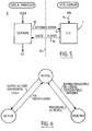
- FIG. 1 of these drawings is a simplified block diagram of a portable electronic device according to the invention.
- Figure 2 is a plan view of the device.
- FIG. 3 is a view along arrow III, FIG. 2.
- FIG. 4 is a view along arrow IV, FIG. 2.
- Figure 5 is a diagram illustrating the principle of identification and authentication.
- Figure 6 is a diagram illustrating the only identification function.
- Figure 7 is a diagram illustrating the authentication function.
- FIG. 8 is a diagram illustrating the use of a device according to the invention with an adapter box directly connected to a terminal.
- FIG. 9 is a diagram illustrating the connection scenario between a terminal and a server using the device of the invention.
- Figure 10 ⁇ is a diagram similar to that of Figure 9, for a wallet function.
- FIG. 11 is a diagram illustrating the advantage of the reading device with three phototransistors for screens of different sizes.
- Figure 12 is a diagram of a self-adaptive circuit to a screen.
- FIG. 13, finally, is a diagram illustrating the operation of the circuit of FIG. 12.
- a portable electronic device 1 of the memory card type comprising an outer box 2 of rectangular parallelepiped shape, and the thickness e ( Figure 3) is small, especially of the order of 5 mm.
- the width l and the length L of the box can be equal to those generally used for credit cards, bank cards, etc., that is to say of the order of 54 mm for l and 85 mm for L.
- the device comprises at least optical reception means R advantageously constituted by phototransistors 3 ( Figure 4) arranged on the edge of a short side of the housing 2, and in particular aligned.
- phototransistors 3 there are three phototransistors.
- FIG. 11 illustrates the advantage of the reading device with at most three phototransistors 3, for screens 48, 49 of different sizes. Screen 48 corresponds to the smallest size, and screen 49 corresponds to the largest size.
- the screen of a terminal generally has a convex shape.
- a pad Q (see FIG. 2), in particular of elastomeric material and of substantially hemispherical shape. , protruding on this edge.
- the reception means R are connected to a microcomputer 4, by means of processing means 5 suitable for self-adapting to a terminal screen 13.
- the transmission of information intended for the means R is carried out by a sequence of light and dark blocks p (see FIG. 8) which appear in a predetermined area of a screen 13 e of terminal 13; due to variations in brightness from one terminal screen to another, a dark block from one terminal may be brighter than a lit block from another terminal.
- the processing means 5 are provided to allow, during an initialization phase, to adjust a comparison threshold as a function of the brightness of the terminal screen.
- the comparison threshold can be defined for each of the phototransistors.
- this threshold can be obtained by discharging a capacitor C, under the control of the microcomputer 4, through a resistor W.
- the charging and discharging of the capacitor C are controlled by the microcomputer 4 to through resistor W by means of an input / output port Z which can be placed in the following states: high state ("1)") for charging the capacitance C, low state ("0 ⁇ ") for its dump ; high impedance state (“HZ”) by maintaining the threshold during reception.
- a comparator K receives, on one input + the signal from the phototransistors and on the other input - the voltage across the terminals of the capacitance C, comparison threshold. Before commissioning, capacity C is charged to its maximum value.
- the capacitance C discharges as represented by the arc of curve U in FIG. 13 (voltage across the capacitance on the ordinate, time on the abscissa), until reaching the desired value, depending on the reception level and determined by the microcomputer.
- the comparison threshold is then kept constant as represented by segment V of FIG. 13, during reception. This comparison threshold is therefore a function of the level of optical reception.
- This variable threshold can be completed by a single fixed for low light levels. The same effect can be obtained by controlling the gain of an amplifier by the microcomputer.
- the coding of the optical transmission is defined so as to reduce the transmission time and adapt to all the networks and protocols connecting the terminal to the central system.
- the main characteristics of this transmission in the context of a computer system are that it is only possible to control the sequencing of the displayed blocks, but not the display times. These characteristics justify the use of at least two phototransistors for the transmission if it is on a computer screen.
- the transmission characteristics on terrestrial or cable television allow the control of display times offering the possibility of synchronous transmission via a single phototransistor.
- the transmission is synchronized using video scanning. This allows the portable device when used with the television to operate and receive information remotely (a few meters) by pointing the product at the screen.
- optical reception and decoding functions recorded in the memory of the microcomputer of the portable device may be specific to the operating mode, telematics or television, but the same device can operate on both supports using one or three phototransistors.
- the device 1 comprises a display 6, preferably with liquid crystal (LCD), forming a rectangular screen 7 (Figure 2) on the housing.
- this screen 7 is designed to display eight alphanumeric characters, aligned.
- the display 6 makes it possible to display information coming from the microcomputer 4.
- a source of electrical energy generally constituted by an electrical cell of reduced dimensions (not shown in the drawings), is provided to supply the various circuits.
- the device comprises a keyboard 8 notably constituted, as shown in FIG. 2, by twelve keys t corresponding respectively to the ten digits 0 ⁇ to 9.
- the keys t are arranged in four rows of three, parallel to the screen 7.
- the keyboard 8 is disposed adjacent to an edge of the housing 2, the left edge as shown in Figure 2, so that a relatively large area 9 is cleared on the right and usable graphically.
- the keyboard 8 allows the user to also enter information into the microcomputer 4.
- the box 2 includes serial input-output means 10 ⁇ connected to the microcomputer 4.
- These means can be a socket or optical coupling means, the optical input advantageously being able to be produced by one of the three phototransistors.
- Such a 10 ⁇ socket allows direct connection to a socket provided in an adapter box 26 which will be discussed in connection with FIG. 8.
- the microcomputer 4 is a masked microcomputer, in C MOS technology. It can be of the type MC 68 HC 0 ⁇ 5B6, of "Motorola", for a version self-programming microcomputer, or of the NEC 7530 ⁇ 8 type for a version with RAM storage memory, or else of the specific circuit type (ASIC) for a version with protected RAM.
- the specific circuit will be developed from a standard microcomputer of the previous types in which the memory protection means will be included. These protection means may be constituted by a blown fuse after writing the memory. It includes a read only memory (ROM) 11 and a storage memory 12.
- the ROM 11 is organized into two areas, namely a program area and a manufacturing area, which will be discussed below.
- the memory 12 is also organized into two areas, namely a data area, and a personalization area, which will be discussed below.
- the data bus and the address bus (not shown in the drawings) of the microcomputer 4 are not accessible from the outside, so as to make it impossible to read or fraudulently modify, from the outside, the information contained by device 1.
- the microcomputer 4 is programmed (the program instructions are stored in the read-only memory 11) so as to make the device active only after entering, on the keyboard 8, a confidential PIN identification code of the user of the device. This confidential code is known only to the holder of the device 1.
- a time delay is advantageously provided to return the microcomputer 4 to the rest state after a predetermined time, in particular 4 minutes, after this microcomputer has been activated by entering the correct confidential code.
- the rest state of the microcomputer 4 corresponds to a state in which this microcomputer does not take into account the information from reception means R.
- the program stored in the memory 11 is further provided for blocking the device 1 after consecutive entry of a certain number of incorrect confidential codes on the keyboard 8, for example four codes.
- the device 1 then becomes unusable, and the reactivation of the device can only be ensured by a special procedure, for example on a server center.
- the device 1 being, in basic application, intended to authorize a connection to a server, from a terminal 13 or equivalent ("MINITEL" console), the microcomputer 4 is programmed (instructions stored in the program area of the memory 11) to ensure an authentication function vis-à-vis the server S. For this, the microcomputer calculates, from information coming from the server, according to an algorithm, a code which appears on the display 6. The user must then enter this code on the keyboard 13c of an i3 terminal (see Figures 7 and 9) connected to the server.
- the calculation of a code is also carried out by the server, according to a similar algorithm, and a comparison of the code calculated by the server and the code entered by the user is carried out by the server; if consistency is found between the two codes, access to the server is given to the user; if there is no consistency between the two calculated codes, access to the server remains prohibited to the user.
- the server or site to be protected is schematically represented in S, on the left part of this figure.
- the dashed line 13 schematically represents a terminal, constituting an interface, located at a distance from the server S and connected, for example by a cable, to the latter.
- This terminal 13 comprises a screen and a keyboard not shown in FIG. 5.
- the device 1 according to the invention is schematically represented on the right part of this FIG. 5.
- the user In order to be able to access the server S from the terminal 13, the user must first enter their personal PIN identification code on the keyboard 8 of the device 1, which is shown diagrammatically by the arrow 14.
- the device 1 If the code is correct, the device 1 is ready to receive information, which can be indicated by a message on the screen 7 ( Figure 2).
- FIG. 5 shows that, during authentication, the device 1 behaves like a key, while the server S behaves like a lock.
- the arrow 15 symbolizes the display on the screen of the terminal 13 of information coming from the server, while the arrow 16 symbolizes the entry of information from the keyboard of the terminal 13.
- the device 1 is in the rest state diagrammed by the upper circle of the diagram.
- the entry of the confidential code, by the user, on the keyboard 8 switches the device to the activated state shown diagrammatically by the circle located at the bottom left of FIG. 6.
- the device is suitable for receiving and processing the optical information appearing on the terminal, to allow the user to access a server.
- the device 1 After a predetermined time by a time delay, in particular of the order of 4 minutes, which corresponds to the end of the identification function, the device 1 returns to the rest state.
- the device 1 switches from the idle state to a deactivated state represented by a circle situated on the right in FIG. 6, prohibiting any use of the device.
- the return from the deactivated state to the rest state can only be ensured by a wake-up procedure which can only be carried out on a server center, in the example described.
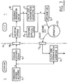
- FIG. 7 is a functional diagram illustrating the authentication function mentioned in connection with the diagram in FIG. 5.
- the left part of this figure corresponds to the communication automaton or lock of the server S.
- the part located to the right of the dashed line (which shows diagrammatically the terminal 13) corresponds to the key constituted by the device 1.
- Block 17 corresponds to the generation of a random number a by the server S.
- Block 18 corresponds to the coding and display on the screen 13 e of the terminal.
- the block 19 corresponds to the optical reception, by the phototransistors 3 of the device 1.
- the block 20 ⁇ corresponds to the decoding, by the microcomputer 4, of the information received.
- Block 21 corresponds to the calculation by the microcomputer 4, of the alphabetical code, from the information received a , according to an algorithm A.
- Block 22 corresponds to the display on the screen 7 of the device 1 of the result x corresponding to code calculated in 21.
- the user or operator shown diagrammatically by a circle 23, after reading on the screen 7, enters the code displayed on the screen 7 on the keyboard 13c of the terminal 13.
- Block 24 corresponds, in the server S, to the calculation of an identification code according to an algorithm B from the random number a , and to the comparison of this calculated code, in the server S, with that entered by the operator 23 on the keyboard 13 c .
- Block 25 relating to device 1, relates to application functions programmed in the microcomputer 4, such as television games, tele bet, pay television, wallet, teleshopping.
- Certain operations require keeping the box 1 relatively long against the screen 13 e of the terminal for the exchange of information.
- an adaptation box 26 (FIG. 8) can be provided for the implementation of the functions requiring a significant exchange of information.
- This housing comprises a housing opening, to the outside, through an opening 27 in which the housing 2 of the device can be engaged.
- the bottom of the housing 27 is equipped with means complementary to the means 10 ⁇ ( Figure 1).
- the box 26 is connected to a cable 28, the other end of which can be connected to a socket 29, in particular of the RS 232 C type, of the terminal 13 or to the peri-computer socket of the MINITEL.
- FIG. 9 is a diagram of the scenario for connecting a terminal 13 to a server S, using the device 1 of the invention. This figure 9 explains the functions described in connection with figure 7.
- the operator from terminal 13, first establishes the connection with the server S, by typing, on the keyboard 13c of terminal 13, a predetermined number.
- Block 30 ⁇ corresponds to the establishment of the connection.
- the server S generates a target (block 32), that is to say shows on the screen 13 e of the terminal light blocks p which, in the example considered, consist of three rectangles aligned as shown in the figure 9.
- the device 1 is in place to receive the information optically.
- the server S in response to pressing the key on the keyboard 13 c , generates and transmits, to the terminal 13, in coded form, a random number, as indicated by block 32.
- the information corresponding to this random number is translated on the screen 13 e by variations in the brightness levels of the blocks p , information which is received by the device 1.
- the latter brings up on the screen 7 an alphabetic or alphanumeric code that the user enters on the keyboard 13 c , which corresponds to block 33 of entry by the server S.
- Block 34 corresponds to the calculation, by the server S, of the code from the random number generated at 32, and to the comparison of this calculated code with that provided from the keyboard 13c .
- the server S can complete the identification of the user, before giving access to the service, by requesting the name of the user (block 35). The user then types his name on the keyboard 13 c .
- the last step accomplished by the server, before giving access to the service is to check, in a file F, as indicated by block 36, the concordance between the identification key, the name and the access rights.
- the user is connected to the service he can use.
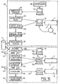
- Figure 10 ⁇ is a diagram illustrating a purse function which can be provided by the device 1 of the invention.
- This function allows the loading of a predetermined sum of money or a number of tokens into the device 1, more precisely into the storage memory 12 of this device, from a server S in which the holder of the device 1 has previously opened and funded an account. This function then allows access to services of the pay-TV type, by subscription or to consumption, or to bets, or other applications by deduction from the amount of money which has been loaded into the memory. storage 12 of device 1.
- the diagram in Figure 10 ⁇ shows an example of implementation of the wallet function.
- the first steps of this program correspond to the prior implementation of the functions of identifying the bearer of the device 1 and of authenticating this bearer with respect to the server. These steps have been represented inside a rectangle 37 and correspond, substantially, to simplified FIG. 9, certain intermediate steps not having been repeated in rectangle 37. The same references have been used in FIG. 10 ⁇ for designate blocks similar to those of FIG. 9 without their description being repeated.
- Block 38 corresponds to the identification of the user by entering the confidential PIN code on the keyboard 8 of the box 2.
- Rectangle 39 encompasses the stages of program concerning the operations after the entry of the wallet service has been given to the user who is in front of the terminal 13 with his device 1.
- the user from the terminal 13, makes, on the keyboard 13c, a request for loading, on his device 1, a sum of money of a determined amount.
- the examination of this request is carried out in block 40 ⁇ ; the server S interrogates its file F to find out if the credit of the user's account is sufficient to allow the loading of the requested amount. If the answer is negative, the request is rejected as shown by exit 41.
- the program of the server S goes to step 42 for the encryption and the certification of the transaction.
- the server S transmits the corresponding information to the terminal 13, this information appearing in the form of light p blocks, clear or dark, on the screen 13 e .
- the device 1 is applied, by the user, against the screen 13 e by its edge provided with phototransistors 3 to collect the information contained in the blocks p .
- the user or operator must then type on the keyboard 13c an instruction corresponding either to the acceptance of the transaction certificate and the bell announced by the server S, or to refuse the certificate; failure to respond by the operator will be considered a refusal.
- Block 43 corresponds to the step of the program of the server S which follows the operator's response. If this response is negative, the transaction is rejected at 44. If the response is positive, the server program goes to the next step represented by block 45 corresponding to the signature, that is to say that, on the server side, the information relating to the transaction is stored as indicated by block 46, while on the device side 1 the amount requested by the operator is actually stored in the memory storage 12 of the device 1 following information transmitted by the server as shown by arrow 47.
- This wallet application can advantageously be implemented using the adapter box 26.
- This payment allows, in particular, the local implementation of game or tele bet application (games of chance, lotteries, matches, horse races, or the like, etc.), in particular from a television or of a "MINITEL”.
- the device 1 of the invention in particular with its purse function, is particularly suitable for pay television.
- the device can be used for remote payment of the subscription to a pay television and receive from the server, in exchange for this payment, a code for the subscription period which will allow this device 1 to control the descrambling of the image.
- the device 1 of the invention can make it possible, still within the framework of a pay-TV, to pay only for a program or a film that the user wants to see on a specific date.
- the device 1, of the invention can provide an account of the films viewed, in particular for audience measurement, and for the payment of copyright.
Abstract
Description
- L'invention est relative à un dispositif portable électronique pour établir une liaison sécurisée avec un serveur via un terminal.
- Il est connu du document WO 87/01835 un tel dispositif comprenant des premiers moyens d'interface pour au moins recevoir des données du serveur via ledit terminal, des seconds moyens d'interface comprenant un clavier et un afficheur pour l'entrée et la lecture de données par un utilisateur dudit dispositif, un microcalculateur propre à traiter les données reçues par le dispositif, des moyens de mémorisation de données à accès protégé et une source d'énergie électrique pour alimenter les divers circuits, ledit microcalculateur étant programmé pour assurer une fonction d'authentification au niveau du serveur en calculant, à partir d'informations provenant du serveur via ledit terminal et lesdits premiers moyens d'interface, suivant un algorithme, un code d'authentification qui est transmis au serveur via ledit terminal, un calcul de code étant également effectué par le serveur, suivant un algorithme semblable à partir desdites informations transmises audit dispositif, l'accès au serveur à partir dudit terminal étant autorisé lorsqu'il y a cohérence entre les codes calculés par le serveur et le microcalculateur et refusé dans le cas contraire.
- Un tel dispositif portable électronique offre un degré d'application limité au contrôle d'accès à un système informatique.
- L'invention a pour but de fournir un dispositif portable électronique, tel que celui défini précédemment, qui permette d'accomplir un maximum de fonctions et d'applications tout en conservant une sûreté d'emploi suffisante et une protection efficace contre des utilisations frauduleuses.
- Il est souhaitable, en outre, qu'un tel dispositif reste d'un encombrement réduit, d'un prix relativement bas pour permettre sa diffusion à grande échelle, et d'une mise en oeuvre simple.
- Un dispositif portable électronique tel que défini dans la revendication 1 offre un fonctionnement autonome en ce sens qu'une fois que des données de transaction, telles qu'une certaine somme d'argent, ont été stockées en mémoire, l'utilisateur peut accéder à des services, des paris ou des jeux indépendamment de tout lien avec le serveur.
- De préférence, lesdits premiers moyens d'interface comprennent des moyens de réception optique tels que des phototransistors.
- De préférence, le microcalculateur est programmé pour ne rendre ce dispositif actif qu'après introduction, sur le clavier, d'un code confidentiel d'identification de l'utilisateur du dispositif.
- Le dispositif portable électronique comprend de préférence une mémoire de stockage pour le stockage d'informations provenant de l'extérieur.
- L'afficheur est avantageusement du type à cristaux liquides (LCD) et peut comporter huit caractères alphanumériques alignés.
- Le dispositif a de préférence la forme d'un boîtier parallélépipédique rectangle de faible épaisseur, notamment de l'ordre de 5 mm. Les moyens de réception optique sont avantageusement constitués par des phototransistors ; ces phototransistors sont disposés sur la tranche d'un petit côté du boîtier. Les phototransistors sont de préférence au plus au nombre de trois, alignés.
- Les phototransistors permettent de recevoir des informations optiques d'un écran ou de composants actifs, de type diodes électroluminescentes, modulés par un signal électrique.
- Les trois phototransistors alignés permettent d'obtenir un dispositif plat qui peut être pointé vers l'écran et peut s'adapter sans paramétrage aux tailles communes d'écrans de terminaux informatiques ou télématiques.
- Le nombre de phototransistors peut être inférieur à trois ; deux phototransistors, tout en permettant de conserver l'avantage de l'adaptation aux différentes tailles d'écran, ne permettent qu'un débit plus faible.
- Une disposition à quatre phototransistors, ou plus, en ligne ne permettrait plus l'adaptation aux différentes tailles d'écran sans paramétrage. Quatre phototransistors disposés en carré permettent une adaptation à tous les écrans, mais impliquent de plaquer le produit à l'écran, rendant le dispositif moins ergonomique et mal adapté aux petits terminaux.
- Avantageusement, les extrémités du côté du boîtier, comportant les phototransistors, sont munies de tampons, notamment en matière èlastomère, de forme sensiblement hémisphérique, permettant un meilleur appui du boîtier contre un écran bombé.
- Le microcalculateur est avantageusement programmé de telle sorte qu'une temporisation soit prévue pour faire retourner le dispositif électronique à l'état de repos, au bout d'un temps prédéterminé, notamment quatre minutes, après que le dispositif a été activé par entrée du code confidentiel correct d'identification.
- Le microcalculateur peut être en outre programmé de manière à bloquer le dispositif après entrée consécutive d'un certain nombre de codes confidentiels erronés, par exemple quatre codes, la réactivation du produit ne pouvant être assurée que par une procédure ou un outil spécial.
- Le dispositif comporte, en dehors d'une horloge système propre au microcalculateur, une horloge temps réel permettant de donner au dispositif une durée de vie limitée, faire fonctionner le dispositif suivant des tranches horaires et/ou dater les opérations, notamment utilisations et transactions effectuées avec ce dispositif portable.
- Le dispositif comporte une mémoire morte (ROM) organisée en deux zones, à savoir :
- une zone programme dans laquelle sont stockées les instructions relatives à :
- la fonction de décodage et réception optique ;
- la fonction d'identification ;
- la fonction d'authentification ;
- les fonctions applicatives, telles que pari, jeu télévisé, porte-monnaie, télé-achat ;
- et une zone fabrication pour mémoriser les informations relatives à la fabrication de la carte et pour initialiser le produit, ces informations concernant :
- le code client ;
- le numéro du masque utilisé pour le microcalculateur ;
- la clé de fabrication, notamment constituée par 128 bits, permettant le contrôle de la personnalisation.
- La mémoire de stockage du dispositif est également organisée en deux zones, à savoir :
- une zone données, pour le stockage d'informations concernant, par exemple, un pari, un jeu, un montant, un nombre de films visionnés dans le cadre d'une télévision à péage, des certificats de transaction, etc... ;
- et une zone personnalisation contenant les informations relatives :
- au code confidentiel (identification);
- à la clé secrète d'authentification ;
- aux paramètres d'exploitation (par exemple blocage de la carte au bout de quatre essais infructueux d'identification) ;
- les diverses clés secrètes éventuellement nécessaires pour les fonctions applicatives.
- La mémoire de stockage peut être une PROM ou une EEPROM, comme dans les cartes à mémoire ou à microprocesseur, ou une RAM sauvegardée.
- Les solutions PROM ou EEPROM nécessitent des tensions et courants d'alimentation relativement importants. Pour des raisons de sécurité, ces mémoires ne peuvent être programmées de l'extérieur nécessitant, comme sur la carte à microprocesseur, une autoprogrammation par le microcalculateur. Ces solutions offrent un bon degré de sécurité mais sont onéreuses ; elles se justifient cependant pour certaines applications.
- Une solution plus simple et moins chère est avantageusement réalisée à partir d'une RAM (mémoire vive), interne au microcalculateur, sauvegardée par l'alimentation du dispositif avec un courant très faible et dont l'accès en écriture pour la zone personnalisation peut être protégée, notamment par un fusible qui est grillé après la phase de personnalisation.
- Le microcalculateur comporte un bus de données et un bus d'adresses non accessibles de l'extérieur, de telle sorte qu'on ne peut lire ni modifier frauduleusement, de l'extérieur, les informations du dispositif.
- Le clavier du dispositif est de préférence un clavier numérique comportant douze à seize touches, à savoir dix touches correspondant aux chiffres 0̸ à 9 et deux à six touches fonctions supplémentaires qui peuvent avantageusement être personnalisées en fonction de l'application (pari, jeu, télévision à péage). L'afficheur est du type alphanumérique LCD.
- L'invention consiste, mises à part les dispositions exposées ci-dessus, en un certain nombre d'autres dispositions dont il sera plus explicitement question ci-après à propos d'un mode de réalisation particulier décrit avec référence aux dessins ci-annexés, mais qui n'est nullement limitatif.
- La figure 1, de ces dessins, est un schéma synoptique simplifié d'un dispositif portable électronique conforme à l'invention.
- La figure 2 est une vue en plan du dispositif.
- La figure 3 est une vue suivant la flèche III, figure 2.
- La figure 4 est une vue suivant la flèche IV, figure 2.
- La figure 5 est un schéma illustrant le principe de l'identification et de l'authentification.
- La figure 6 est un schéma illustrant la seule fonction d'identification.
- La figure 7 est un schéma illustrant la fonction d'authentification.
- La figure 8 est un schéma illustrant l'utilisation d'un dispositif selon l'invention avec un boîtier d'adaptation directement raccordé à un terminal.
- La figure 9 est un schéma illustrant le scénario de connexion entre un terminal et un serveur en utilisant le dispositif de l'invention.
- La figure 10̸ est un schéma semblable à celui de la figure 9, pour une fonction porte-monnaie.
- La figure 11 est un schéma illustrant l'intérêt du dispositif de lecture à trois phototransistors pour des écrans de tailles différentes.
- La figure 12 est un schéma d'un circuit d'autoadaptativité à un écran.
- La figure 13, enfin, est un diagramme illustrant le fonctionnment du circuit de la figure 12.
- En se reportant aux dessins, notamment aux figures 1 à 4, on peut voir un dispositif portable électronique 1, du genre carte à mémoire, comprenant un boîtier extérieur 2 de forme parallélépipédique rectangle, et dont l'épaisseur e (figure 3) est faible, notamment de l'ordre de 5 mm. La largeur l et la longueur L du boîtier peuvent être égales à celles utilisées de manière générale pour les cartes de crédit, cartes bancaires, etc..., c'est-à-dire de l'ordre de 54 mm pour l et de 85 mm pour L.
- Le dispositif comprend au moins des moyens de réception optique R avantageusement constitués par des phototransistors 3 (figure 4) disposés sur la tranche d'un petit côté du boîtier 2, et en particulier alignés. Dans l'exemple considéré, les phototransistors sont au nombre de trois. La figure 11 illustre l'intérêt du dispositif de lecture à au plus trois phototransistors 3, pour des écrans 48, 49 de tailles différentes. L'écran 48 correspond à la plus petite taille, et l'écran 49 à la plus grande taille.
- Lorsque l'on passe d'une taille d'écran à une autre, l'écartement entre les centres des pavés lumineux p1, p2, p3 va changer, alors que l'écartement entre les phototransistors 3 reste constant.
- Avec la disposition à au plus trois phototransistors, l'ensemble des pavés est toujours centré et il est possible d'allonger les pavés droite et gauche p2, p3, suivant la direction d'alignement D des phototransistors, de manière à être sûr que, quelle que soit la taille de l'écran, les phototransistors droite et gauche se trouvent toujours en face d'une partie des pavés p2, p3 correspondants.
- L'écran d'un terminal a généralement une forme convexe. Pour faciliter l'application de la tranche du boîtier 2, munie des phototransistors 3, contre cet écran, on prévoit avantageusement, à chaque extrémité de la tranche, un tampon Q (voir figure 2), notamment en matière élastomère et de forme sensiblement hémisphérique, faisant saillie sur cette tranche.
- Les moyens de réception R, comme illustré sur la figure 1, sont reliés à un microcalculateur 4, par l'intermédiaire de moyens de traitement 5 propres à réaliser une auto-adaptativité à un écran de terminal 13.
- En effet, la transmission d'informations destinées aux moyens R s'effectue par une séquence de pavés lumineux et sombres p (voir figure 8) qui apparaissent en une zone prédéterminée d'un écran 13e de terminal 13 ; en raison des variations de luminosité d'un écran de terminal à un autre, il est possible qu'un pavé sombre d'un terminal soit plus lumineux qu'un pavé éclairé d'un autre terminal. Pour éviter les distorsions de lecture d'un terminal à l'autre, les moyens de traitement 5 sont prévus pour permettre, au cours d'une phase d'initialisation, d'ajuster un seuil de comparaison en fonction de la luminosité de l'écran du terminal. Pour tenir compte de la dispersion de sensibilité des phototransistors, le seuil de comparaison peut être défini pour chacun des phototransistors.
- Comme visible sur la figure 12, ce seuil peut être obtenu par la décharge d'une capacité C, sous le contrôle du microcalculateur 4, à travers une résistance W. La charge et la décharge de la capacité C sont contrôlées par le microcalculateur 4 à travers la résistance W au moyen d'un port d'entrée/sortie Z qui peut être placé dans les états suivants : état haut ("1)") pour la charge de la capacité C, état bas ("0̸") pour sa décharge ; état haute impédance ("HZ") par le maintien du seuil pendant la réception. Un comparateur K reçoit, sur une entrée + le signal provenant des phototransistors et sur l'autre entrée - la tension aux bornes de la capacité C, seuil de comparaison. Avant mise en service, la capacité C est chargée à sa valeur maximale. Pendant l'initialisation, la capacité C se décharge comme représenté par l'arc de courbe U de la figure 13 (tension aux bornes de la capacité en ordonnées, temps en abscisse), jusqu'à atteindre la valeur souhaitée, fonction du niveau de réception et déterminée par le microcalculateur. Le seuil de comparaison est alors maintenu constant comme représenté par le segment V de la figure 13, pendant la réception. Ce seuil de comparaison est donc fonction du niveau de réception optique. Ce seuil variable peut être complété par un seul fixe pour les faibles luminosités. Le même effet peut être obtenu en contrôlant le gain d'un amplificateur par le microcalculateur.
- Le codage de la transmission optique est défini de manière à diminuer le temps de transmission et s'adapter à tous les réseaux et protocoles reliant le terminal au système central. Les caractéristiques principales de cette transmissions dans le cadre d'un système informatique sont qu'il est seulement possible de maîtriser le séquencement des pavés affichés mais pas les temps d'affichage. Ces caractéristiques justifient l'utilisation d'au moins deux phototransistors pour la transmis si on sur un écran informatique. Les caractéristiques de transmission sur télévision hertzienne ou câblée permettent le contrôle des temps d'affichage offrant la possibilité d'une transmission synchrone par l'intermédiaire d'un seul phototransistor. La synchronisation de la transmission s'effectue à l'aide du balayage video. Ceci permet au dispositif portable lorsqu'il est utilisé avec la télévision de fonctionner et recevoir les informations à distance (quelques mètres) en pointant le produit vers l'écran.
- Les fonctions de réception et décodage optiques inscrites dans la mémoire du microcalculateur du dispositif portable pourront être spécifiques au mode d'exploitation , télématique ou télévision, mais le même dispositif pourra fonctionner sur les deux supports en utilisant un ou trois phototransistors.
- Le dispositif 1 comprend un afficheur 6, de préférence à cristaux liquides (LCD), formant un écran rectangulaire 7 (figure 2) sur le boîtier. De préférence, cet écran 7 est prévu pour afficher huit caractères alphanumériques, alignés. L'afficheur 6 permet de visualiser des informations provenant du microcalculateur 4.
- Une source d'énergie électrique, généralement constituée par une pile électrique de dimensions réduites (non représentée sur les dessins), est prévue pour alimenter les divers circuits.
- Le dispositif comporte un clavier 8 notamment constitué, comme représenté sur la figure 2, par douze touches t correspondant respectivement aux dix chiffres 0̸ à 9. Les touches t sont disposées en quatre rangées de trois, parallèles à l'écran 7. Le clavier 8 est disposé adjacent à un bord du boîtier 2, le bord gauche selon la représentation de la figure 2, pour qu'une surface 9, relativement importante, soit dégagée sur la droite et exploitable graphiquement.
- Le clavier 8 permet à l'utilisateur d'entrer également des informations dans le microcalculateur 4.
- Avantageusement, le boîtier 2 comporte des moyens d'entrée-sortie série 10̸ reliés au microcalculateur 4. Ces moyens peuvent être une prise ou des moyens de couplage optique, l'entrée optique pouvant avantageusement être réalisée par un des trois phototransistors. Une telle prise 10̸ permet un raccordement direct sur une prise prévue dans un boîter d'adaptation 26 dont il sera question à propos de la figure 8.
- Le microcalculateur 4 est un microcalculateur masqué, en technologie C MOS. Il peut être du type MC 68 HC 0̸5B6, de "Motorola", pour une version microcalculateur autoprogrammable, ou du type NEC 7530̸8 pour une version à mémoire de stockage RAM, ou alors du type circuit spécifique (ASIC) pour une version à RAM protégée. Le circuit spécifique sera développé à partir d'un microcalculateur standard des types précédents dans lesquels on inclura les moyens de protection de la mémoire. Ces moyens de protection pourront être constitués par un fusible grillé après écriture de la mémoire. Il comporte une mémoire morte (ROM) 11 et une mémoire de stockage 12.
- La mémoire morte 11 est organisée en deux zones à savoir une zone programme et une zone fabrication, dont il sera question plus loin.
- La mémoire 12 est également organisée en deux zones à savoir une zone données, et une zone personnalisation, dont il sera question plus loin.
- Le bus de données et le bus d'adresses (non représentés sur les dessins) du microcalculateur 4 ne sont pas accessibles de l'extérieur, de manière à rendre impossible une lecture ou une modification frauduieuse, depuis l'extérieur, des informations contenues par le dispositif 1.
- Le microcalculateur 4 est programmé (les instructions du programme sont stockées dans la mémoire morte 11) pour ne rendre actif le dispositif qu'après introduction, sur le clavier 8, d'un code confidentiel d'identification PIN de l'utilisateur du dispositif. Ce code confidentiel est connu seulement du titulaire du dispositif 1.
- Une temporisation on est avantageusement prévue pour faire retourner le microcalculateur 4 à l'état de repos au bout d'un temps prédéterminé, notamment de 4 minutes, après que ce microcalculateur a été activé par entrée du code confidentiel correct. L'état de repos du microcalculateur 4 correspond à un état dans lequel ce microcalculateur ne prend pas en compte les informations provenant des moyens de réception R.
- Le programme stocké dans la mémoire 11 est en outre prévu pour bloquer le dispositif 1 après entrée consécutive d'un certain nombre de codes confidentiels erronés sur le clavier 8, par exemple quatre codes. Le dispositif 1 devient alors inutilisable, et la réactivation du dispositif ne peut être assuré que par une procédure spéciale par exemple sur un centre serveur.
- Le dispositif 1 étant, en application de base, destiné à autoriser une connexion sur un serveur, à partir d'un terminal 13 ou équivalent (console de "MINITEL"), le microcalculateur 4 est programmé (instructions stockées dans la zone programme de la mémoire 11) pour assurer une fonction d'authentification vis-à-vis du serveur S. Pour cela le microcalculateur calcule, à partir d'informations provenant du serveur, suivant un algorithme, un code qui apparaît sur l'afficheur 6. L'utilisateur doit alors entrer ce code sur le clavier 13c d'un terminal i3 (voir figures 7 et 9) relié au serveur. Le calcul d'un code est effectué également par le serveur, suivant un algorithme semblable, et une comparaison du code calculé par le serveur et du code introduit par l'utilisateur est effectué par le serveur ; si une cohérence es t constatée entre les deux codes, l'accès au serveur est donné à l'utilisateur ; si aucune cohérence n'apparaît entre les deux codes calculés, l'accès au serveur reste interdit à l'utilisateur.
- Les figures 5 à 7, et la figure 9 permettent de mieux illustrer ces caractéristiques.
- Sur la figure 5 on a schématiquement représenté en S le serveur ou site à protéger, sur la partie gauche de cette figure. Le trait mixte 13 représente schématiquement un terminal, constituant une interface, située à distance du serveur S et reliée, par exemple par un câble, à ce dernier. Ce terminal 13 comporte un écran et un clavier non représentés sur la figure 5. Le dispositif 1 conforme à l'invention est schématiquement représenté sur la partie droite de cette figure 5. Pour pouvoir accéder au serveur S depuis le terminal 13, l'utilisateur doit d'abord introduire son code personnel d'identification PIN sur le clavier 8 du dispositif 1, ce qui est schématisé par la flèche 14.
- Si le code est correct, le dispositif 1 est prêt à recevoir des informations, ce qui peut être signalé par un message sur l'écran 7 (figure 2).
- Le déroulement des opérations sera décrit plus en détail à propos des figures 7 et 9. Le schéma de la figure 5 fait apparaître que, lors de l'authentification, le dispositif 1 se comporte comme une clé, tandis que le serveur S se comporte comme une serrure. La flèche 15 symbolise l'affichage sur l'écran du terminal 13 d' informations provenant du serveur, tandis que la flèche 16 symbolise la saisie d'informations à partir du clavier du terminal 13.
- Le schéma de la figure 6 illustre la fonction d'identification.
- Initialement, le dispositif 1 est à l'état de repos schématisé par le cercle supérieur du schéma.
- L'entrée du code confidentiel, par l'utilisateur, sur le clavier 8 fait passer le dispositif à l'état activé schématisé par le cercle situé en bas à gauche de la figure 6. Dans cet état, le dispositif est propre à recevoir et à traiter les informations optiques apparaissant sur le terminal, pour permettre à l'utilisateur d'accéder à un serveur.
- Au bout d'un temps prédéterminé par une temporisation, notamment de l'ordre de 4 minutes, qui correspond à la fin de la fonction d'identification, le dispositif 1 retourne à l'état de repos.
- S'il y a entrée consécutive de plusieurs codes confidentiels erronés, par exemple quatre codes successifs erronés, le dispositif 1 passe de l'état de repos à un état désactivé représenté par un cercle situé à droite sur la figure 6, interdisant toute utilisation du dispositif.
- Le retour de l'état désactivé à l'état de repos ne peut être assuré que par une procédure de réveil qui ne peut être effectuée que sur un centre serveur, dans l'exemple décrit.
- La figure 7 est un schéma fonctionnel illustrant la fonction d'authentification évoquée à propos du schéma de la figure 5. La partie gauche de cette figure correspond à l'automate de communication ou serrure du serveur S. La partie située à droite du trait mixte (lequel schématise le terminal 13) correspond à la clé constituée par le dispositif 1.
- Le bloc 17 correspond à la génération d'un nombre aléatoire a par le serveur S. Le bloc 18 correspond au codage et à l'affichage sur l'écran 13e du terminal. Le bloc 19 correspond à la réception optique, par les phototransistors 3 du dispositif 1. Le bloc 20̸ correspond au décodage, par le microcalculateur 4, de l'information reçue. Le bloc 21 correspond au calcul par le microcalculateur 4, du code alphabétique, à partir de l'information reçue a, suivant un algorithme A. Le bloc 22 correspond à l'affichage sur l'écran 7 du dispositif 1 du résultat x correspondant au code calculé en 21.
- L'utilisateur ou opérateur, schématisé par un cercle 23, après lecture sur l'écran 7, introduit sur le clavier 13c du terminal 13 le code affiché sur l'écran 7.
- Le bloc 24 correspond, dans le serveur S, au calcul d'un code d'identification suivant un algorithme B à partir du nombre aléatoire a, et à la comparaison de ce code calculé, dans le serveur S, avec celui introduit par l'opérateur 23 sur le clavier 13c.
- Si la comparaison entre les deux codes établit une cohérence, en accord avec les algorithmes A et B, l'accès du système est donné à l'opérateur 23.
- En cas d'absence de cohérence, l'accès demeure interdit.
- Le bloc 25, relatif au dispositif 1, concerne des fonctions applicatives programmées dans le microcalculateur 4, telles que jeux de télévision, télé pari, télévision à péage, porte-monnaie, télé-achat.
- Certaines opérations nécessitent de maintenir relativement longtemps le boîtier 1 contre l'écran 13e du terminal pour les échanges d'informations.
- Pour éviter à l'opérateur d'avoir à tenir le boîtier 2, on peut prévoir un boîtier d'adaptation 26 (figure 8) pour la mise en oeuvre des fonctions nécessitant un échange d'informations important. Ce boîtier comporte un logement débouchant, à l'extérieur, par une ouverture 27 dans laquelle peut être engagé le boîtier 2 du dispositif. Le fond du logement 27 est équipé de moyens complémentaires des moyens 10̸ (figure 1). Le boîtier 26 est raccordé à un câble 28 dont l'autre extrémité peut être branchée sur une prise 29, notamment du type RS 232 C, du terminal 13 ou sur la prise péri-informatique du MINITEL.
- La figure 9 est un schéma du scénario de connexion d'un terminal 13 à un serveur S, à l'aide du dispositif 1 de l'invention. Cette figure 9 explicite les fonctions décrites à propos de la figure 7.
- L'opérateur, à partir du terminal 13, établit tout d'abord la connexion avec le serveur S, en tapant, sur le clavier 13c du terminal 13, un numéro prédéterminé. Le bloc 30̸ correspond à l'établissement de la connexion. Le serveur S génère une mire (bloc 32) c'est-à-dire fait apparaître sur l'écran 13e du terminal des pavés lumineux p qui, dans l'exemple considéré, sont constitués par trois rectangles alignés comme représenté sur la figure 9.
- L'utilisateur présente alors le dispositif 1 manière à placer les phototransistors 3 en face des pavés p. Le dispositif 1 est en place pour recevoir les informations par voie optique. Bien entendu, auparavant, l'utilisateur a dû valider le dispositif 1 en introduisant sur le clavier 8 du boîtier 2 son code confidentiel permettant son identification.
- L'utilisateur appuie alors sur une touche du clavier 13c du terminal. Le serveur S, en réponse à l'enfoncement de la touche du clavier 13c, génère et transmet, au terminal 13, sous forme codée, un nombre aléatoire, comme indiqué par le bloc 32. Les informations correspondant à ce nombre aléatoire se traduisent sur l'écran 13e par des variations de niveaux de luminosité des pavés p, informations qui sont reçues par le dispositif 1. Ce dernier fait apparaître sur l'écran 7 un code alphabétique ou alphanumérique que l'utilisateur introduit sur le clavier 13c, ce qui correspond au bloc 33 de saisie par le serveur S.
- Le bloc 34 correspond au calcul, par le serveur S, du code à partir du nombre aléatoire généré en 32, et à la comparaison de ce code calculé avec celui fourni à partir du clavier 13c.
- Lorsqu'il y a cohérence de ces deux codes, le serveur S peut compléter l'identification de l'utilisateur, avant de donner accès au service, en demandant le nom de l'utilisateur (bloc 35). L'utilisateur tape alors son nom sur le clavier 13c.
- La dernière étape accomplie par le serveur, avant de donner accès au service, est de vérifier, dans un fichier F, comme indiqué par le bloc 36, la concordance entre la clé d'identification, le nom et les droits d'accès. Lorsque la concordance est établie, l'utilisateur est connecté au service qu'il peut utiliser.
- La figure 10̸ est un schéma illustrant une fonction porte-monnaie qui peut être assurée par le dispositif 1 de l'invention.
- Cette fonction permet le chargement d'une somme d'argent prédéterminée ou d'un nombre de jetons dans le dispositif 1, plus précisément dans la mémoire de stockage 12 de ce dispositif, à partir d'un serveur S dans lequel le détenteur du dispositif 1 a préalablement ouvert et approvisionné un compte. Cette fonction permet, ensuite, d'accéder à des services du type télévision à péage, par abonnement ou à la consommation, ou à des paris, ou d'autres applications par prélèvement sur la somme d'argent qui a été chargée dans la mémoire de stockage 12 du dispositif 1.
- Le schéma de la figure 10̸ présente un exemple d'implantation de la fonction porte-monnaie.
- Les premières étapes de ce programme correspondent à la mise en oeuvre préalable des fonctions d'identification du porteur du dispositif 1 et d'authentification de ce porteur vis à vis du serveur. Ces étapes ont été représentées à l'intérieur d'un rectangle 37 et correspondent, sensiblement, à la figure 9 simplifiée, certaines étapes intermédiaires n'ayant pas été reprises dans le rectangle 37. Les mêmes références ont été utilisées sur la figure 10̸ pour désigner des blocs semblables à ceux de la figure 9 sans que leur description soit reprise. Le bloc 38 correspond à l'identification de l'utilisateur par introduction du code PIN confidentiel sur le clavier 8 du boîtier 2.
- Le rectangle 39 englobe les étapes du programme concernant les opérations après que l'entrée du service porte-monnaie a été donnée à l'utilisateur qui se trouve devant le terminal 13 avec son dispositif 1.
- Ll'utilisateur, à partir du terminal 13, effectue, sur le clavier 13c, une demande de chargement, sur son dispositif 1, d'une somme d'argent d'un montant déterminé. L'examen de cette demande est effectué dans le bloc 40̸ ; le serveur S interroge son fichier F pour savoir si le crédit du compte de l'utilisateur est suffisant pour permettre le chargement de la somme demandée. Si la réponse est négative, la demande est rejetée comme schématisé par la sortie 41.
- Si la réponse est affirmative, le programme du serveur S passe à l'étape 42 pour le chiffrement et la certification de la transaction. Le serveur S transmet les informations correspondantes au terminal 13, ces informations apparaissant sous la forme de pavés lumineux p clairs ou obscurs sur l'écran 13e. Le dispositif 1 est appliqué, par l'utilisateur, contre l'écran 13e par sa tranche munie des phototransistors 3 pour recueillir les informations contenues dans les pavés p.
- L'utilisateur ou opérateur doit alors taper sur le clavier 13c une instruction correspondant soit à l'acceptation du certificat de transaction et de la sonne annoncée par le serveur S, soit refuser le certificat ; l'absence de réponse de l'opérateur sera considérée comme un refus.
- Le bloc 43 correspond à l'étape du programme du serveur S qui fait suite à la réponse de l'opérateur. Si cette réponse est négative, la transaction est rejetée en 44. Si la réponse est positive, le programme du serveur passe à l'étape suivante représentée par le bloc 45 correspondant à la signature, c'est-à-dire que, du côté du serveur, les informations relatives à la transaction sont mémorisées comme indiqué par le bloc 46, tandis que du côté dispositif 1 la somme demandée par l'opérateur est effectivement stockée dans la mémoire de stockage 12 du dispositif 1 suite aux informations transmises par le serveur comme sohématisé par la flèche 47.
- On peut prévoir, également, de mémoriser dans le dispositif 1 les informations relatives à la transaction opérée (certificat de transaction stocké dans le dispositif 1).
- Cette application porte-monnaie peut être avantageusement mise en oeuvre à l'aide du boîtier d'adaptation 26.
- Inversement, à partir d'un dispositif 1 dans lequel a été chargée une somme d'argent, il est possible d'accéder à des services, des paris, ou des jeux, en prélevant la somme à payer sur celle stockée dans la mémoire de stockage 12.
- Ce paiement permet, en particulier, la mise en oeuvre locale d'application de jeu ou télé pari (jeux de hasard, loteries, matches, courses de chevaux, ou analogues, etc...), notamment à partir d'une télévision ou d'un "MINITEL".
- Le dispositif 1 de l'invention, notamment avec sa fonction porte-monnaie, est particulièrement adapté pour la télévision à péage.
- Périodiquement, le dispositif peut servir au paiement à distance de l'abonnement à une télévision à péage et recevoir, du serveur, en échange de ce paiement, un code pour la période d'abonnement qui permettra à ce dispositif 1 de contrôler le désembrouillage de l'image.
- Le dispositif 1 de l'invention peut permettre, toujours dans le cadre d'une télévision à péage, de payer uniquement pour une émission ou un film que l'utilisateur souhaite voir à une date déterminée.
- Le dispositif 1, de l'invention, peut fournir un compte-rendu des films visionnés, notamment pour la mesure de l'audience, et pour le paiement des droits d'auteur.
- Dans le cadre d'une animation télévisée ou similaire, il est possible d'envoyer des informations depuis une station émettrice, par voie hertzienne ou par des réseaux câblés de télévision, télématiques, informatiques, etc..., en faisant apparaître une mire sur l'écran du récepteur ou terminal, mire destinée à être lue par les phototransistors du dispositif 1 de l'invention plaqué sur l'écran. Les informations ainsi transmises peuvent permettre de sélectionner des gagnants à un jeu télévisé, et de mettre en place des jeux ou paris en direct sur la télévision.
Claims (15)
- Dispositif portable électronique pour établir une liaison sécurisée avec un serveur (S) via un terminal (13), ledit dispositif comprenant des premiers moyens d'interface (R, 10) pour au moins recevoir des données du serveur via ledit terminal, des seconds moyens d'interface comprenant un clavier (8) et un afficheur (6) pour l'entrée et la lecture de données par un utilisateur dudit dispositif, un microcalculateur (4) propre à traiter les données reçues par le dispositif, des moyens de mémorisation de données (12) à accès protégé et une source d'énergie électrique pour alimenter les divers circuits, ledit microcalculateur (4) étant programmé pour assurer une fonction d'authentification au niveau du serveur (S) en calculant, à partir d'informations provenant du serveur via ledit terminal et lesdits premiers moyens d'interface, suivant un algorithme, un code d'authentification qui est transmis au serveur via ledit terminal, un calcul de code étant également effectué par le serveur, suivant un algorithme semblable à partir desdites informations transmises audit dispositif, l'accès au serveur à partir dudit terminal étant autorisé lorsqu'il y a cohérence entre les codes calculés par le serveur (S) et le microcalculateur (4) et refusé dans le cas contraire, caractérisé en ce que ledit microcalculateur (4) est en outre programmé pour assurer :- la réception via ledit terminal et lesdits premiers moyens d'interface de données chiffrées en provenance du serveur qui sont représentatives d'une transaction effectuée par ledit utilisateur avec ledit serveur via ledit terminal et la mémorisation desdites données de transaction dans lesdits moyens de mémorisation en réponse à la signature de ladite transaction,- l'accès de l'utilisateur à au moins un service ou similaire au moyen dudit dispositif, en fonction desdites données de transaction mémorisées dans les moyens de mémorisation.
- Dispositif selon la revendication 1, caractérisé en ce que lesdites données reçues et mémorisées sous la commande du microcalculateur (4) comprennent des informations relatives à la transaction opérée.
- Dispositif selon la revendication 2, caractérisé en ce que ladite transaction consiste à stocker une somme d'argent d'un montant déterminé dans ledit dispositif et lesdites informations comprennent ledit montant.
- Dispositif selon la revendication 3, caractérisé en ce que ledit microcalculateur (4) est programmé pour assurer, en réponse à l'accès audit service, le prélèvement d'une somme à payer sur celle stockée.
- Dispositif selon l'une quelconque des revendications 2 à 4, caractérisé en ce que lesdites données reçues et mémorisées sous la commande du microcalculateur (4) comprennent un certificat de transaction.
- Dispositif selon l'une quelconque des revendications 1 à 5, caractérisé en ce que ledit microcalculateur (4) est programmé pour assurer la mémorisation desdites données en réponse à la transmission par le serveur (S) d'informations représentatives de ladite signature de la transaction, lesdites données étant également mémorisées dans le serveur (S) en réponse à ladite signature.
- Dispositif selon l'une quelconque des revendications 1 à 6, caractérisé en ce que la réception par ledit dispositif desdites données chiffrées représentatives d'une transaction est conditionnée par l'acceptation préalable de ladite transaction au niveau du serveur.
- Dispositif selon l'une quelconque des revendications 1 à 7, caractérisé par le fait que le microcalculateur (4) est programmé pour ne rendre le dispositif actif qu'après introduction, sur le clavier (8), d'un code confidentiel d'identification de l'utilisateur du dispositif.
- Dispositif selon la revendication 8, caractérisé par le fait que le microcalculateur (4) est programmé de manière à bloquer le dispositif après entrées consécutives d'un certain nombre de codes confidentiels erronés, la réactivation du produit ne pouvant être assurée que par une procédure ou outil spécial.
- Dispositif selon l'une quelconque des revendications 1 à 9, caractérisé par le fait qu'il comprend une mémoire de stockage (12) organisée en deux zones, à savoir une zone données et une zone personnalisation.
- Dispositif selon la revendication 10, caractérisé par le fait que la mémoire de stockage (12) est réalisée en RAM et que l'accès en écriture de la zone personnalisation est protégée par un fusible grillé après personnalisation.
- Dispositif selon l'une quelconque des revendications 1 à 11, caractérisé en ce que lesdits premiers moyens d'interface comprennent des moyens de réception optique.
- Dispositif selon la revendication 12, caractérisé par le fait que les moyens de réception optique sont constitués par des phototransistors (3).
- Dispositif selon l'une quelconque des revendications précédentes, caractérisé par le fait que le clavier (8) est un clavier numérique associé à des touches de fonction et l'afficheur (6) est du type alphanumérique.
- Dispositif selon l'une quelconque des revendications précédentes, caractérisé par le fait que les premiers moyens d'interface comportent des moyens d'entrée/sortie (10) reliés au microcalculateur (4) pour permettre une entrée et une sortie série, et qu'un boîtier d'adaptation (26) est prévu avec un logement débouchant à l'extérieur par une ouverture (27) dans laquelle peut être engagé le dispositif, le fond du logement (27) étant équipé de moyens complémentaires des moyens d'entrée/sortie (10) du dispositif, le boîtier d'adaptation (26) étant raccordé à un câble (28) dont l'autre extrémité peut être branchée sur une prise (29) d'un terminal (13).
Applications Claiming Priority (3)
| Application Number | Priority Date | Filing Date | Title |
|---|---|---|---|
| FR8805306 | 1988-04-21 | ||
| FR8805306A FR2630561B1 (fr) | 1988-04-21 | 1988-04-21 | Dispositif portable electronique destine a etre utilise en liaison avec un ecran |
| EP89401130A EP0338936B1 (fr) | 1988-04-21 | 1989-04-21 | Dispositif portable électronique destiné à être utilisé en liaison avec un écran |
Related Parent Applications (2)
| Application Number | Title | Priority Date | Filing Date |
|---|---|---|---|
| EP89401130.3 Division | 1989-04-21 | ||
| EP89401130A Division EP0338936B1 (fr) | 1988-04-21 | 1989-04-21 | Dispositif portable électronique destiné à être utilisé en liaison avec un écran |
Publications (3)
| Publication Number | Publication Date |
|---|---|
| EP0552822A2 true EP0552822A2 (fr) | 1993-07-28 |
| EP0552822A3 EP0552822A3 (en) | 1994-08-24 |
| EP0552822B1 EP0552822B1 (fr) | 1999-05-19 |
Family
ID=9365537
Family Applications (2)
| Application Number | Title | Priority Date | Filing Date |
|---|---|---|---|
| EP89401130A Expired - Lifetime EP0338936B1 (fr) | 1988-04-21 | 1989-04-21 | Dispositif portable électronique destiné à être utilisé en liaison avec un écran |
| EP93105918A Expired - Lifetime EP0552822B1 (fr) | 1988-04-21 | 1989-04-21 | Dispositif portable électronique pour établir une liaison sécurisée avec un serveur via un terminal |
Family Applications Before (1)
| Application Number | Title | Priority Date | Filing Date |
|---|---|---|---|
| EP89401130A Expired - Lifetime EP0338936B1 (fr) | 1988-04-21 | 1989-04-21 | Dispositif portable électronique destiné à être utilisé en liaison avec un écran |
Country Status (10)
| Country | Link |
|---|---|
| US (1) | US4910775A (fr) |
| EP (2) | EP0338936B1 (fr) |
| JP (1) | JPH01276358A (fr) |
| AT (2) | ATE180334T1 (fr) |
| CA (1) | CA1300757C (fr) |
| DE (2) | DE68929002T2 (fr) |
| ES (2) | ES2049830T3 (fr) |
| FR (1) | FR2630561B1 (fr) |
| HK (1) | HK27397A (fr) |
| SG (1) | SG52263A1 (fr) |
Cited By (4)
| Publication number | Priority date | Publication date | Assignee | Title |
|---|---|---|---|---|
| FR2769446A1 (fr) | 1997-10-02 | 1999-04-09 | Achille Joseph Marie Delahaye | Systeme d'identification et d'authentification |
| WO2001045025A1 (fr) * | 1999-12-17 | 2001-06-21 | Thomson Licensing S.A. | Procede de gestion de jeu a distance securise |
| US7451401B2 (en) * | 1999-05-28 | 2008-11-11 | Nokia Corporation | Real-time, interactive and personalized video services |
| US10555169B2 (en) | 2005-12-21 | 2020-02-04 | Onespan North America Inc. | System and method for dynamic multifactor authentication |
Families Citing this family (57)
| Publication number | Priority date | Publication date | Assignee | Title |
|---|---|---|---|---|
| US5468947A (en) * | 1986-08-08 | 1995-11-21 | Norand Corporation | Pocket size data capture unit with processor and shell modules |
| US5227614A (en) * | 1986-08-15 | 1993-07-13 | Norand Corporation | Core computer processor module, and peripheral shell module assembled to form a pocket size data capture unit |
| US6621942B1 (en) | 1989-09-29 | 2003-09-16 | Intermec Ip Corp. | Data capture apparatus with handwritten data receiving component |
| US6149062A (en) * | 1988-01-14 | 2000-11-21 | Intermec Ip Corp. | Interface with hand-held data capture terminal, proximity and label sensing, and enhanced sensitivity and power efficiency |
| US5136644A (en) * | 1988-04-21 | 1992-08-04 | Telecash | Portable electronic device for use in conjunction with a screen |
| US5297200A (en) * | 1989-04-01 | 1994-03-22 | Nighthawk Electronics Limited | Computer security system |
| US6714983B1 (en) | 1989-04-14 | 2004-03-30 | Broadcom Corporation | Modular, portable data processing terminal for use in a communication network |
| US7388742B2 (en) * | 1989-04-14 | 2008-06-17 | Broadcom Corporation | Portable computerized data communication device |
| FR2658375B2 (fr) * | 1989-05-25 | 1994-04-22 | Adventure | Dispositif electronique destine a permettre la participation d'un individu a un programme telediffuse. |
| EP0667019B1 (fr) * | 1989-06-07 | 2003-09-17 | Intermec IP Corp. | Systeme portatif de saisie de donnees a modules interchangeables |
| KR100191811B1 (ko) * | 1989-10-24 | 1999-06-15 | 이브 오드베르 | 매체 또는 이와 유사한 것에 대하여 대중의 관심을 유발시키기 위한 휴대용 전자장치 |
| US6431451B1 (en) * | 1991-02-25 | 2002-08-13 | Intermec Ip Corp. | Hand-held data capture system with interchangeable modules |
| EP0474923A1 (fr) * | 1990-09-11 | 1992-03-18 | Sigma-Delta N.V. | Appareil pour participer à des jeux de quiz, transmis ou enregistrés |
| US5519433A (en) * | 1991-11-20 | 1996-05-21 | Zing Systems, L.P. | Interactive television security through transaction time stamping |
| US5343239A (en) * | 1991-11-20 | 1994-08-30 | Zing Systems, L.P. | Transaction based interactive television system |
| US5734413A (en) * | 1991-11-20 | 1998-03-31 | Thomson Multimedia S.A. | Transaction based interactive television system |
| CA2117694A1 (fr) * | 1992-03-18 | 1993-09-30 | John R. Martin | Jeu a communications avec une station eloignee a niveau de securite eleve |
| DE4216223A1 (de) * | 1992-05-19 | 1993-11-25 | Peter Wittstock | Vorrichtung zur Wiedergabe von Kurzfilmen und/oder Werbespots und Quizfragen insbesondere in Freizeitanlagen |
| US20090322277A1 (en) * | 1992-11-30 | 2009-12-31 | Broadcom Corporation | Portable computerized data communication device |
| ATE161345T1 (de) * | 1993-03-25 | 1998-01-15 | Philipp J Schneider | Elektronisches kleingerät |
| EP0617386A1 (fr) * | 1993-03-25 | 1994-09-28 | Philipp J. Schneider | Petit appareil électronique |
| US5523794A (en) * | 1993-04-16 | 1996-06-04 | Mankovitz; Roy J. | Method and apparatus for portable storage and use of data transmitted by television signal |
| EP0719369B1 (fr) * | 1993-09-13 | 1998-12-09 | Rockwell International Corporation | Appareil de mise en oeuvre a distance d'une commande |
| EP0647912A1 (fr) * | 1993-10-07 | 1995-04-12 | TELESIA MICROELETTRONICA S.r.l. | Appareil électronique pour jeux basés sur le temps et/ou activités semi-interactives |
| US5432851A (en) * | 1993-10-21 | 1995-07-11 | Tecsec Incorporated | Personal computer access control system |
| US5488571A (en) * | 1993-11-22 | 1996-01-30 | Timex Corporation | Method and apparatus for downloading information from a controllable light source to a portable information device |
| US5960344A (en) * | 1993-12-20 | 1999-09-28 | Norand Corporation | Local area network having multiple channel wireless access |
| US6925439B1 (en) * | 1994-06-20 | 2005-08-02 | C-Sam, Inc. | Device, system and methods of conducting paperless transactions |
| US5590038A (en) * | 1994-06-20 | 1996-12-31 | Pitroda; Satyan G. | Universal electronic transaction card including receipt storage and system and methods of conducting electronic transactions |
| CA2219285A1 (fr) * | 1995-04-25 | 1996-10-31 | Timex Corporation | Transmission de texte et de donnees a partir d'un tube cathodique |
| US5655966A (en) * | 1995-08-07 | 1997-08-12 | Intergame | Method and apparatus for cashless bartop gaming system operation |
| US6697415B1 (en) * | 1996-06-03 | 2004-02-24 | Broadcom Corporation | Spread spectrum transceiver module utilizing multiple mode transmission |
| US5894552A (en) * | 1997-08-15 | 1999-04-13 | The United States Of America As Represented By The Secretary Of The Navy | Method and apparatus for manually switching to a secured network |
| TW469379B (en) * | 1998-02-16 | 2001-12-21 | Sony Computer Entertainment Inc | Portable electronic device |
| DE19853730C2 (de) * | 1998-11-23 | 2001-10-04 | Ibm | Verfahren und Vorrichtung zum Identifizieren und Behandeln von kritischen Chipkartenkommandos |
| US7308426B1 (en) | 1999-08-11 | 2007-12-11 | C-Sam, Inc. | System and methods for servicing electronic transactions |
| US6970850B1 (en) * | 1999-10-27 | 2005-11-29 | Automated Business Companies | Proximity service provider system |
| US6705520B1 (en) | 1999-11-15 | 2004-03-16 | Satyan G. Pitroda | Point of sale adapter for electronic transaction device |
| FR2811446B1 (fr) * | 2000-07-07 | 2004-01-16 | Dixet | Procede de securisation utilisant une transmission d'information par voie optique et disque optique pour la mise en oeuvre de ce procede |
| US7529563B1 (en) | 2000-07-10 | 2009-05-05 | Pitroda Satyan G | System for distribution and use of virtual stored value cards |
| IL141441A0 (en) * | 2001-02-15 | 2002-03-10 | Aharonson Dov | Smart card having an optical communication circuit and a method for use thereof |
| US6523967B2 (en) | 2001-05-01 | 2003-02-25 | Technology Creations, Inc. | Electroluminescent apparatus for illuminating a portable electronic or computing device |
| US7076663B2 (en) * | 2001-11-06 | 2006-07-11 | International Business Machines Corporation | Integrated system security method |
| US20050044387A1 (en) * | 2003-08-18 | 2005-02-24 | Ozolins Helmars E. | Portable access device |
| US7519827B2 (en) * | 2004-04-06 | 2009-04-14 | Verigy (Singapore) Pte. Ltd. | Provisioning and use of security tokens to enable automated test equipment |
| JP4619231B2 (ja) * | 2005-07-29 | 2011-01-26 | 株式会社ジェイテクト | 安全plc |
| US7905777B2 (en) * | 2005-08-04 | 2011-03-15 | Igt | Methods and apparatus for auctioning an item via a gaming device |
| CA2621844C (fr) | 2005-09-08 | 2014-04-22 | Cardlab Aps | Carte de transaction dynamique et procede permettant d'ecrire des informations sur cette carte |
| US8216065B2 (en) | 2005-09-09 | 2012-07-10 | Igt | Gaming system having multiple adjacently arranged gaming machines which each provide a component for a multi-component game |
| EP2667344A3 (fr) | 2005-10-06 | 2014-08-27 | C-Sam, Inc. | Services transactionnels |
| US7857699B2 (en) * | 2006-11-01 | 2010-12-28 | Igt | Gaming system and method of operating a gaming system having a bonus participation bidding sequence |
| DE102007052734B4 (de) * | 2007-06-27 | 2010-12-30 | Universität Tübingen | Vorrichtung und Verfahren zur abhör- und manipulationssicheren Verschlüsselung für Online-Accounts |
| EP2073153A1 (fr) * | 2007-12-18 | 2009-06-24 | Gemplus | Procédé pour autoriser une communication avec un dispositif électronique portable, telle qu'un accès à une zone mémoire, dispositif et système électroniques correspondants |
| EP3035230A1 (fr) | 2014-12-19 | 2016-06-22 | Cardlab ApS | Procédé et ensemble permettant de générer un champ magnétique |
| MA41187A (fr) | 2014-12-19 | 2021-04-07 | Cardlab Aps | Procédé et ensemble pour générer un champ magnétique et procédé de fabrication d'un ensemble |
| EP3082071A1 (fr) | 2015-04-17 | 2016-10-19 | Cardlab ApS | Dispositif pour produire un champ magnétique et procédé associé |
| JP7025135B2 (ja) * | 2016-06-24 | 2022-02-24 | エヌエイチエヌ コーポレーション | 簡易決済方法および簡易決済システム |
Citations (5)
| Publication number | Priority date | Publication date | Assignee | Title |
|---|---|---|---|---|
| FR2582421A1 (fr) * | 1985-05-24 | 1986-11-28 | Lefevre Jean Pierre | Appareil d'authentification d'identite |
| WO1987001835A1 (fr) * | 1985-09-12 | 1987-03-26 | Basil Eliseus Philipsz | Systeme informatique avec securite |
| FR2588396A1 (fr) * | 1985-10-04 | 1987-04-10 | Esparseil Claude | Dispositif electronique de protection d'un acces, notamment a un logiciel et cle pour un tel dispositif |
| WO1987003977A1 (fr) * | 1985-12-26 | 1987-07-02 | Gordian Systems | Cle a circuit integre de commande d'acces a des systemes et a des logiciels informatiques et/ou de mise en securite de communications |
| EP0234954A2 (fr) * | 1986-02-28 | 1987-09-02 | Intellicard International, Inc. | Carte magnétique avec code d'identification |
Family Cites Families (24)
| Publication number | Priority date | Publication date | Assignee | Title |
|---|---|---|---|---|
| US3906460A (en) * | 1973-01-11 | 1975-09-16 | Halpern John Wolfgang | Proximity data transfer system with tamper proof portable data token |
| FR2389284A1 (fr) * | 1977-04-27 | 1978-11-24 | Cii Honeywell Bull | Systeme de traitement d'informations protegeant le secret d'informations confidentielles |
| FR2401459A1 (fr) * | 1977-08-26 | 1979-03-23 | Cii Honeywell Bull | Support d'information portatif muni d'un microprocesseur et d'une memoire morte programmable |
| FR2448826A1 (fr) * | 1979-02-06 | 1980-09-05 | Telediffusion Fse | Carte d'abonnement pour recepteur de videotex et poste de chargement de ladite carte |
| US4339798A (en) * | 1979-12-17 | 1982-07-13 | Remote Dynamics | Remote gaming system |
| FR2492135B1 (fr) * | 1980-09-16 | 1988-01-22 | Cii Honeywell Bull | Appareil de distribution d'objets et d'acquisition de services |
| GB2092343B (en) * | 1981-01-30 | 1985-10-09 | Chalmers David Arthur | Portable data carrier incorporating manually presettable processing modes |
| EP0076255A1 (fr) * | 1981-04-07 | 1983-04-13 | BENTON, William M. | Systeme de verification de transactions utilisant une liaison de communication de donnees optiques |
| GB2126460A (en) * | 1982-07-12 | 1984-03-21 | Peter Kurt Shreck | Video response testing apparatus |
| US4558175A (en) * | 1982-08-02 | 1985-12-10 | Leonard J. Genest | Security system and method for securely communicating therein |
| US4496158A (en) * | 1982-12-13 | 1985-01-29 | Sanders Associates, Inc. | Electro-optical sensor for color television games and training systems |
| US4593376A (en) * | 1983-04-21 | 1986-06-03 | Volk Larry N | System for vending program cartridges which have circuitry for inhibiting program usage after preset time interval expires |
| US4536647A (en) * | 1983-07-15 | 1985-08-20 | Atalla Corporation | Pocket banking terminal, method and system |
| GB2143636A (en) * | 1983-07-22 | 1985-02-13 | Stephen Kenneth Buss | A circuit arrangement and method for detecting markers in a microfilm scanner |
| US4799258A (en) * | 1984-02-13 | 1989-01-17 | National Research Development Corporation | Apparatus and methods for granting access to computers |
| US4599489A (en) * | 1984-02-22 | 1986-07-08 | Gordian Systems, Inc. | Solid state key for controlling access to computer software |
| US4575621A (en) * | 1984-03-07 | 1986-03-11 | Corpra Research, Inc. | Portable electronic transaction device and system therefor |
| US4592546A (en) * | 1984-04-26 | 1986-06-03 | David B. Lockton | Game of skill playable by remote participants in conjunction with a live event |
| DE3585464D1 (de) * | 1984-06-19 | 1992-04-09 | Casio Computer Co Ltd | Intelligente karte. |
| US4800590A (en) * | 1985-01-14 | 1989-01-24 | Willis E. Higgins | Computer key and computer lock system |
| US4701601A (en) * | 1985-04-26 | 1987-10-20 | Visa International Service Association | Transaction card with magnetic stripe emulator |
| FR2605430B1 (fr) * | 1986-10-15 | 1991-06-07 | Audebert Yves | Dispositif electronique destine a permettre l'utilisation d'une carte a memoire avec un systeme auquel elle est destinee |
| US4796181A (en) * | 1986-10-24 | 1989-01-03 | Wiedemer John D | Billing system for computer software |
| US4829166A (en) * | 1986-12-01 | 1989-05-09 | Froelich Ronald W | Computerized data-bearing card and reader/writer therefor |
-
1988
- 1988-04-21 FR FR8805306A patent/FR2630561B1/fr not_active Expired - Lifetime
- 1988-06-09 CA CA000569079A patent/CA1300757C/fr not_active Expired - Lifetime
- 1988-07-11 US US07/217,254 patent/US4910775A/en not_active Expired - Lifetime
- 1988-07-29 JP JP63191999A patent/JPH01276358A/ja active Pending
-
1989
- 1989-04-21 DE DE68929002T patent/DE68929002T2/de not_active Expired - Fee Related
- 1989-04-21 AT AT93105918T patent/ATE180334T1/de not_active IP Right Cessation
- 1989-04-21 EP EP89401130A patent/EP0338936B1/fr not_active Expired - Lifetime
- 1989-04-21 SG SG1996001585A patent/SG52263A1/en unknown
- 1989-04-21 ES ES89401130T patent/ES2049830T3/es not_active Expired - Lifetime
- 1989-04-21 ES ES93105918T patent/ES2133340T3/es not_active Expired - Lifetime
- 1989-04-21 DE DE68911573T patent/DE68911573T2/de not_active Expired - Fee Related
- 1989-04-21 EP EP93105918A patent/EP0552822B1/fr not_active Expired - Lifetime
- 1989-04-21 AT AT89401130T patent/ATE99068T1/de not_active IP Right Cessation
-
1997
- 1997-03-06 HK HK27397A patent/HK27397A/xx not_active IP Right Cessation
Patent Citations (5)
| Publication number | Priority date | Publication date | Assignee | Title |
|---|---|---|---|---|
| FR2582421A1 (fr) * | 1985-05-24 | 1986-11-28 | Lefevre Jean Pierre | Appareil d'authentification d'identite |
| WO1987001835A1 (fr) * | 1985-09-12 | 1987-03-26 | Basil Eliseus Philipsz | Systeme informatique avec securite |
| FR2588396A1 (fr) * | 1985-10-04 | 1987-04-10 | Esparseil Claude | Dispositif electronique de protection d'un acces, notamment a un logiciel et cle pour un tel dispositif |
| WO1987003977A1 (fr) * | 1985-12-26 | 1987-07-02 | Gordian Systems | Cle a circuit integre de commande d'acces a des systemes et a des logiciels informatiques et/ou de mise en securite de communications |
| EP0234954A2 (fr) * | 1986-02-28 | 1987-09-02 | Intellicard International, Inc. | Carte magnétique avec code d'identification |
Non-Patent Citations (5)
| Title |
|---|
| IBM TECHNICAL DISCLOSURE BULLETIN., vol.28, no.3, Ao}t 1985, NEW YORK US pages 1109 - 1122 'Transaction completion code based on digital signatures' * |
| IBM TECHNICAL DISCLOSURE BULLETIN., vol.30, no.3, Ao}t 1987, NEW YORK US pages 1262 - 1265 'Personal transaction card' * |
| LA RECHERCHE, vol.17, no.176, Avril 1986, PARIS FR, XP97270 UGON ET AL. 'Les cartes à puce' * |
| ONDE ELECTRIQUE, vol.64, no.1, Janvier 1984, PARIS FR pages 18 - 23 GUION CHRISTIAN 'La carte à mémoire: choix technologiques et caractéristiques' * |
| TOSHIBA REVIEW, no.159, 1987, TOKYO JP pages 30 - 33 TAMADA ET AL. 'IC card system' * |
Cited By (6)
| Publication number | Priority date | Publication date | Assignee | Title |
|---|---|---|---|---|
| FR2769446A1 (fr) | 1997-10-02 | 1999-04-09 | Achille Joseph Marie Delahaye | Systeme d'identification et d'authentification |
| US7451401B2 (en) * | 1999-05-28 | 2008-11-11 | Nokia Corporation | Real-time, interactive and personalized video services |
| WO2001045025A1 (fr) * | 1999-12-17 | 2001-06-21 | Thomson Licensing S.A. | Procede de gestion de jeu a distance securise |
| FR2802677A1 (fr) * | 1999-12-17 | 2001-06-22 | Thomson Multimedia Sa | Procede de gestion de jeu a distance securise |
| US7294057B2 (en) | 1999-12-17 | 2007-11-13 | Thomson Licensing | Secure method for remote game management |
| US10555169B2 (en) | 2005-12-21 | 2020-02-04 | Onespan North America Inc. | System and method for dynamic multifactor authentication |
Also Published As
| Publication number | Publication date |
|---|---|
| CA1300757C (fr) | 1992-05-12 |
| HK27397A (en) | 1997-03-06 |
| EP0338936B1 (fr) | 1993-12-22 |
| ATE99068T1 (de) | 1994-01-15 |
| SG52263A1 (en) | 1998-09-28 |
| FR2630561A1 (fr) | 1989-10-27 |
| JPH01276358A (ja) | 1989-11-06 |
| FR2630561B1 (fr) | 1992-11-27 |
| DE68929002D1 (de) | 1999-06-24 |
| EP0552822A3 (en) | 1994-08-24 |
| ATE180334T1 (de) | 1999-06-15 |
| ES2133340T3 (es) | 1999-09-16 |
| DE68911573D1 (de) | 1994-02-03 |
| US4910775A (en) | 1990-03-20 |
| DE68929002T2 (de) | 1999-09-16 |
| EP0552822B1 (fr) | 1999-05-19 |
| DE68911573T2 (de) | 1994-07-21 |
| EP0338936A1 (fr) | 1989-10-25 |
| ES2049830T3 (es) | 1994-05-01 |
Similar Documents
| Publication | Publication Date | Title |
|---|---|---|
| EP0552822B1 (fr) | Dispositif portable électronique pour établir une liaison sécurisée avec un serveur via un terminal | |
| EP0425347B1 (fr) | Dispositif portable électronique pour fidéliser un public à un média ou similaire | |
| EP0399897B1 (fr) | Système de participation individuelle à un programme télédiffusé | |
| EP0077238B1 (fr) | Procédé et dispositif pour authentifier la signature d'un message signé | |
| EP0426541B1 (fr) | Procédé de protection contre l'utilisation frauduleuse de cartes à microprocesseur, et dispositif de mise en oeuvre | |
| EP0317400B1 (fr) | Dispositif et procédé de sécurisation d'échange de données entre un terminal vidéotex et un serveur | |
| FR2685510A1 (fr) | Procede d'authentification, par un milieu exterieur, d'un objet portatif connecte a ce milieu par l'intermediaire d'une ligne de transmission, et systeme pour la mise en óoeuvre. | |
| WO2001093216A1 (fr) | Procede de cryptographie et microcircuit pour carte a puce | |
| EP0049650A1 (fr) | Appareil de distribution d'objets et d'acquisition de services | |
| FR2767624A1 (fr) | Dispositif portable electronique pour systeme de communication securisee, et procede d'initialisation de ses parametres | |
| EP1255178A1 (fr) | Dispositif de sécurité pour transaction en ligne | |
| CA2398317A1 (fr) | Systeme et procede de securisation des transmissions d'informations | |
| FR2885246A1 (fr) | Terminal nomade de transactions electroniques securise et systeme de transactions electroniques securise | |
| FR2750273A1 (fr) | Procede de rechargement de cartes prepayees virtuelles | |
| FR2810759A1 (fr) | Procede pour effectuer une transaction commerciale en ligne par l'intermediaire d'un reseau de communication et dispositif electronique pour passer des commandes commerciales en ligne | |
| EP1354288B1 (fr) | Procede utilisant les cartes de paiement electroniques pour securiser les transactions | |
| EP0817144B1 (fr) | Procédé de contrôle de l'utilisation d'un messageur, messageur fonctionnant selon ce procédé et carte à puce pour l'accès conditionné à un messageur | |
| EP1965342A1 (fr) | Procédé pour effectuer une transaction entre un module de paiement et un module de sécurité | |
| EP1502234B1 (fr) | Procede de transmission de donnees entre une carte a puce et un utilisateur, lecteur de carte et carte pour la mise en oeuvre de ce procede | |
| BE899285A (fr) | Dispositif portatif pour la memorisation et le transfert de donnees. | |
| FR2647619A1 (fr) | Dispositif electronique destine a permettre la participation d'un individu a un programme telediffuse | |
| WO1998044464A1 (fr) | Procede de certification d'un cumul dans un lecteur | |
| FR2648587A1 (fr) | Dispositif de securisation d'echange de donnees entre un terminal videotex et un serveur et procede d'initialisation d'un tel dispositif | |
| WO2005031665A1 (fr) | Systeme de machines à sous securise | |
| FR2582830A1 (fr) | Dispositif permettant de determiner une relation entre un document reference et un individu |
Legal Events
| Date | Code | Title | Description |
|---|---|---|---|
| PUAI | Public reference made under article 153(3) epc to a published international application that has entered the european phase |
Free format text: ORIGINAL CODE: 0009012 |
|
| AC | Divisional application: reference to earlier application |
Ref document number: 338936 Country of ref document: EP |
|
| AK | Designated contracting states |
Kind code of ref document: A2 Designated state(s): AT BE CH DE ES FR GB IT LI NL SE |
|
| RIN1 | Information on inventor provided before grant (corrected) |
Inventor name: DELAHAYE, ACHILLE Inventor name: AUDEBERT, YVES |
|
| PUAL | Search report despatched |
Free format text: ORIGINAL CODE: 0009013 |
|
| AK | Designated contracting states |
Kind code of ref document: A3 Designated state(s): AT BE CH DE ES FR GB IT LI NL SE |
|
| 17P | Request for examination filed |
Effective date: 19950213 |
|
| 17Q | First examination report despatched |
Effective date: 19971024 |
|
| GRAG | Despatch of communication of intention to grant |
Free format text: ORIGINAL CODE: EPIDOS AGRA |
|
| GRAG | Despatch of communication of intention to grant |
Free format text: ORIGINAL CODE: EPIDOS AGRA |
|
| GRAH | Despatch of communication of intention to grant a patent |
Free format text: ORIGINAL CODE: EPIDOS IGRA |
|
| GRAH | Despatch of communication of intention to grant a patent |
Free format text: ORIGINAL CODE: EPIDOS IGRA |
|
| GRAA | (expected) grant |
Free format text: ORIGINAL CODE: 0009210 |
|
| AC | Divisional application: reference to earlier application |
Ref document number: 338936 Country of ref document: EP |
|
| AK | Designated contracting states |
Kind code of ref document: B1 Designated state(s): AT BE CH DE ES FR GB IT LI NL SE |
|
| RAP1 | Party data changed (applicant data changed or rights of an application transferred) |
Owner name: ACTIVCARD EUROPE |
|
| REF | Corresponds to: |
Ref document number: 180334 Country of ref document: AT Date of ref document: 19990615 Kind code of ref document: T |
|
| REG | Reference to a national code |
Ref country code: CH Ref legal event code: EP |
|
| GBT | Gb: translation of ep patent filed (gb section 77(6)(a)/1977) |
Effective date: 19990519 |
|
| REG | Reference to a national code |
Ref country code: CH Ref legal event code: NV Representative=s name: KIRKER & CIE SA |
|
| REF | Corresponds to: |
Ref document number: 68929002 Country of ref document: DE Date of ref document: 19990624 |
|
| REG | Reference to a national code |
Ref country code: ES Ref legal event code: FG2A Ref document number: 2133340 Country of ref document: ES Kind code of ref document: T3 |
|
| PLBE | No opposition filed within time limit |
Free format text: ORIGINAL CODE: 0009261 |
|
| STAA | Information on the status of an ep patent application or granted ep patent |
Free format text: STATUS: NO OPPOSITION FILED WITHIN TIME LIMIT |
|
| 26N | No opposition filed | ||
| REG | Reference to a national code |
Ref country code: GB Ref legal event code: IF02 |
|
| PGFP | Annual fee paid to national office [announced via postgrant information from national office to epo] |
Ref country code: SE Payment date: 20020319 Year of fee payment: 14 |
|
| PGFP | Annual fee paid to national office [announced via postgrant information from national office to epo] |
Ref country code: FR Payment date: 20020328 Year of fee payment: 14 |
|
| PGFP | Annual fee paid to national office [announced via postgrant information from national office to epo] |
Ref country code: DE Payment date: 20020410 Year of fee payment: 14 |
|
| PGFP | Annual fee paid to national office [announced via postgrant information from national office to epo] |
Ref country code: CH Payment date: 20020411 Year of fee payment: 14 |
|
| PGFP | Annual fee paid to national office [announced via postgrant information from national office to epo] |
Ref country code: GB Payment date: 20020416 Year of fee payment: 14 |
|
| PGFP | Annual fee paid to national office [announced via postgrant information from national office to epo] |
Ref country code: ES Payment date: 20020429 Year of fee payment: 14 Ref country code: AT Payment date: 20020429 Year of fee payment: 14 |
|
| PGFP | Annual fee paid to national office [announced via postgrant information from national office to epo] |
Ref country code: NL Payment date: 20020430 Year of fee payment: 14 |
|
| PGFP | Annual fee paid to national office [announced via postgrant information from national office to epo] |
Ref country code: BE Payment date: 20020514 Year of fee payment: 14 |
|
| PG25 | Lapsed in a contracting state [announced via postgrant information from national office to epo] |
Ref country code: GB Free format text: LAPSE BECAUSE OF NON-PAYMENT OF DUE FEES Effective date: 20030421 Ref country code: AT Free format text: LAPSE BECAUSE OF NON-PAYMENT OF DUE FEES Effective date: 20030421 |
|
| PG25 | Lapsed in a contracting state [announced via postgrant information from national office to epo] |
Ref country code: SE Free format text: LAPSE BECAUSE OF NON-PAYMENT OF DUE FEES Effective date: 20030422 Ref country code: ES Free format text: LAPSE BECAUSE OF NON-PAYMENT OF DUE FEES Effective date: 20030422 |
|
| PG25 | Lapsed in a contracting state [announced via postgrant information from national office to epo] |
Ref country code: LI Free format text: LAPSE BECAUSE OF NON-PAYMENT OF DUE FEES Effective date: 20030430 Ref country code: CH Free format text: LAPSE BECAUSE OF NON-PAYMENT OF DUE FEES Effective date: 20030430 Ref country code: BE Free format text: LAPSE BECAUSE OF NON-PAYMENT OF DUE FEES Effective date: 20030430 |
|
| BERE | Be: lapsed |
Owner name: *ACTIVCARD EUROPE Effective date: 20030430 |
|
| PG25 | Lapsed in a contracting state [announced via postgrant information from national office to epo] |
Ref country code: NL Free format text: LAPSE BECAUSE OF NON-PAYMENT OF DUE FEES Effective date: 20031101 Ref country code: DE Free format text: LAPSE BECAUSE OF NON-PAYMENT OF DUE FEES Effective date: 20031101 |
|
| NLV4 | Nl: lapsed or anulled due to non-payment of the annual fee |
Effective date: 20031101 |
|
| EUG | Se: european patent has lapsed | ||
| GBPC | Gb: european patent ceased through non-payment of renewal fee |
Effective date: 20030421 |
|
| REG | Reference to a national code |
Ref country code: CH Ref legal event code: PL |
|
| PG25 | Lapsed in a contracting state [announced via postgrant information from national office to epo] |
Ref country code: FR Free format text: LAPSE BECAUSE OF NON-PAYMENT OF DUE FEES Effective date: 20031231 |
|
| REG | Reference to a national code |
Ref country code: FR Ref legal event code: ST |
|
| REG | Reference to a national code |
Ref country code: ES Ref legal event code: FD2A Effective date: 20030422 |
|
| PG25 | Lapsed in a contracting state [announced via postgrant information from national office to epo] |
Ref country code: IT Free format text: LAPSE BECAUSE OF NON-PAYMENT OF DUE FEES;WARNING: LAPSES OF ITALIAN PATENTS WITH EFFECTIVE DATE BEFORE 2007 MAY HAVE OCCURRED AT ANY TIME BEFORE 2007. THE CORRECT EFFECTIVE DATE MAY BE DIFFERENT FROM THE ONE RECORDED. Effective date: 20050421 |