EP0552743B1 - Automatic slide-on panel loading system - Google Patents
Automatic slide-on panel loading system Download PDFInfo
- Publication number
- EP0552743B1 EP0552743B1 EP93100811A EP93100811A EP0552743B1 EP 0552743 B1 EP0552743 B1 EP 0552743B1 EP 93100811 A EP93100811 A EP 93100811A EP 93100811 A EP93100811 A EP 93100811A EP 0552743 B1 EP0552743 B1 EP 0552743B1
- Authority
- EP
- European Patent Office
- Prior art keywords
- pack
- supporting surface
- fact
- panels
- stack
- Prior art date
- Legal status (The legal status is an assumption and is not a legal conclusion. Google has not performed a legal analysis and makes no representation as to the accuracy of the status listed.)
- Expired - Lifetime
Links
Images

Classifications
-
- B—PERFORMING OPERATIONS; TRANSPORTING
- B65—CONVEYING; PACKING; STORING; HANDLING THIN OR FILAMENTARY MATERIAL
- B65H—HANDLING THIN OR FILAMENTARY MATERIAL, e.g. SHEETS, WEBS, CABLES
- B65H3/00—Separating articles from piles
- B65H3/24—Separating articles from piles by pushers engaging the edges of the articles
- B65H3/242—Separating articles from piles by pushers engaging the edges of the articles for separating a part of the pile, i.e. several articles at once
-
- B—PERFORMING OPERATIONS; TRANSPORTING
- B65—CONVEYING; PACKING; STORING; HANDLING THIN OR FILAMENTARY MATERIAL
- B65H—HANDLING THIN OR FILAMENTARY MATERIAL, e.g. SHEETS, WEBS, CABLES
- B65H3/00—Separating articles from piles
- B65H3/46—Supplementary devices or measures to assist separation or prevent double feed
- B65H3/54—Pressing or holding devices
-
- B—PERFORMING OPERATIONS; TRANSPORTING
- B65—CONVEYING; PACKING; STORING; HANDLING THIN OR FILAMENTARY MATERIAL
- B65H—HANDLING THIN OR FILAMENTARY MATERIAL, e.g. SHEETS, WEBS, CABLES
- B65H2301/00—Handling processes for sheets or webs
- B65H2301/40—Type of handling process
- B65H2301/42—Piling, depiling, handling piles
- B65H2301/422—Handling piles, sets or stacks of articles
- B65H2301/4228—Dividing piles
Definitions
- the present invention relates to a slide-on system for automatically loading panels of wood, plastic or similar material, and which is especially suitable for applications involving thin, undulated panels.
- Known slide-on panel loading systems feature a transfer bar with push members by which a pack of panels is pushed off the top of a stack into the work station.
- a transfer bar with push members by which a pack of panels is pushed off the top of a stack into the work station.
- one or more panels underneath the pack being loaded invariably inch forward in the direction of the work station, due to friction between the underside of the bottom panel in the moving pack and the top surface of the panel underneath, which friction is further accentuated by the weight of the moving pack and the undulated design of the panels.
- Slippage of the underlying panels not forming part of the pack for loading creates serious problems by virtue of the offset position assumed by the underlying panels in relation to the moving pack. This invariably results in handling and aligning problems when loading the next pack, and very often in high-cost machine stoppages for restoring acceptable loading conditions.
- German Patent DE 3619676 A1 it is described a slide-on panel loading system that comprises a pushing member that presents an ending part that is beak like.
- An inferior part of the ending part is movable under the push of an advancement device, and the superior part, that presents a plane surface normal to the feeding direction of the panels as high as the pack of panel that we have to feed on, is movable in comparison with the inferior part under the push of a pushing device mounted on the inferior part.
- This kind of slide-on panel loading system presents the disadvantage that, in case of adhesion of one panel to the others, it's impossible to stop the panels disposed under the pack of panel we want to move, with the consequence that the thickness of the pack of panel varies in an undetermined way.
- an automatic slide-on panel loading system comprising:
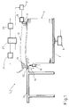
- Number 1 in Fig.s 1 and 2 indicates a slide-on system for automatically loading panels 2 arranged in a stack 3 on a platform 4 moved parallel to itself by a fluid actuator 5.
- System 1 also comprises a bar 6 moved parallel to itself by an electric motor 7 connected to bar 6 in known manner and therefore shown only schematically.
- the ends of bar 6 slide along respective slideways 8, and, on the side facing stack 3, bar 6 presents two push members 11 which, as bar 6 moves forward, push a pack 12 of panels 2 on to the supporting surface 13 of a work station featuring production machines (not shown).
- the height of platform 4 and therefore of the top panel 2 in stack 3 determines the height of, and therefore the number of panels 2 in, pack 12.
- system 1 comprises, between surface 13 and stack 3, a device 14 for arresting the panels 2 underlying pack 12 and which tend to inch towards surface 13.
- Device 14 comprises two parallel vertical plates 15 positioned a given distance apart and each connected to a respective fluid actuator 16. At the top end, each plate 15 presents a tapered tip having a vertical face on the side facing stack 3, and an oblique face on the side facing surface 13.
- Each plate 15 is movable vertically along a respective slideway 17 housed inside a recess 18 (Fig.3) formed along the lateral edge of supporting surface 13 facing stack 3.
- each plate 15 is mechanically integral with, e.g. welded to, a respective horizontal plate 21, which, on the opposite side to that connected mechanically to plate 15, presents a vertical through hole 22.
- Each actuator 16 presents a vertical threaded rod 23 fitted firstly with a nut 24, then itself fitted through hole 22 in plate 21, and finally fitted with a second nut 25.
- a preloaded helical spring 26 is wound about rod 23, and which provides for pressing plate 21 on to nut 25 and so pushing plate 15 upwards.
- system 1 presents an electronic control system 27 for controlling actuators 5 and 16 via respective fluid systems 28 and 31 (shown schematically), as well as for controlling motor 7.
- control system 27 provides for controlling translation of platform 4, bar 6 and plates 15.
- Two sensors 32, one for each plate 15, are connected to control system 27 for signaling to system 27 the passage of pack 12 over the gap housing device 14.
- each sensor 32 consists of a microswitch housed in a recess 33 formed in the top face of supporting surface 13, over recess 18.
- Each microswitch presents a fixed blade 34 inside recess 33 and in which is defined a first electrical contact; and a flexible blade 35 extending upwards beyond the top face of supporting surface 13, and in which is defined a second electrical contact.
- sensors 32 signal to system 27 the arrival of pack 12 on to supporting surface 13, by virtue of the weight of pack 12 flexing blade 35 inwards of recess 33 and so connecting the two electrical contacts of the microswitch.
- rods 23 of actuators 16 are set to the bottom limit position, so that the tip of plates 15 does not extend beyond the top face of supporting surface 13; and, having determined the height of pack 12 for loading, bar 6 is moved towards supporting surface 13.
- the height of pack 12 is determined by adjusting the height of platform 4, or, if push members 11 are equipped with a manual or automatic height adjusting device, by adjusting the height of push members 11 in relation to bar 6.
- Systems are also available on the market for determining the height of pack 12 by adjusting the height of both platform 4 and push members 11.
- pack 12 On reaching the edge of supporting surface 13, pack 12 activates sensors 32, which, via control system 27, operate actuators 16 so as to raise rods 23 and, via springs 26, also plates 15, and so that the tips of plates 15 contact the bottom panel 2 in the moving pack 12.
- the upward travel of rods 23 may be regulated by control system 27 as a function of the height of pack 12.
- the tips of plates 15 remain permanently contacting bottom panel 2 in the moving pack 12, by virtue of the pressure exerted on the respective plate 15-plate 21 assemblies by springs 26, which thus act as dampers for counteracting any vertical displacement of plates 15 caused by the undulated design of the moving pack 12.
- plates 15 may also be used for aligning panels 2 in the next pack 12, by increasing the upward travel of rods 23 and, consequently, plates 15 as compared with that required for contacting the bottom panel 2 in the moving pack 12, and by moving bar 6 just enough to align all the panels 2 in the new pack 12 against plates 15.
- control system 27 lowers rods 23 and moves bar 6 towards supporting surface 13; and, upon pack 12 activating sensors 32, rods 23 are raised, so that plates 15 arrest the panels 2 underneath pack 12 and which tend to inch towards supporting surface 13.
- the device for arresting the underlying panels remains permanently contacting the bottom edge of the moving pack by means of pressure exerted on the bottom edge throughout the loading stage, thus ensuring effective arrest of the underlying panels throughout the loading operation.
- the panel arrester may also be used for aligning the panels in the next pack.
- push members 11 may be designed differently from those described herein, and may, for example, be known types in the form of an articulated quadrilateral, or feature grips for gripping pack 12.
- the height of pack 12 may be determined using methods other than those described or mentioned by way of alternatives herein.
- Panel arrester 14 may present one or more plates 15, which in turn may be shaped differently from those described herein.
- device 14 may present a single central plate 15 with a large-area stop face. Changes may also be made to the manner in which the tip of plate 15 is maintained permanently contacting the bottom edge of pack 12. For example, provision may be made for a spring acting directly on plate 15, or the functions of spring 26 may be performed by actuator 16 of device 14 itself.
- device 14 may present, for example, an electric motor or lever mechanism for operating plate 15.
- the passage of pack 12 on to supporting surface 13 may be detected by sensors other than those described herein, e.g. optical, proximity or pressure sensors.
- sensors 32 which may, for example, be fitted to the tip of plate 15, the upward movement of which may be effected, not by sensors, but after a given operating time of bar 6.
Landscapes
- Engineering & Computer Science (AREA)
- Mechanical Engineering (AREA)
- Sheets, Magazines, And Separation Thereof (AREA)
- Press Drives And Press Lines (AREA)
- Stacking Of Articles And Auxiliary Devices (AREA)
- Devices For Post-Treatments, Processing, Supply, Discharge, And Other Processes (AREA)
- Casting Support Devices, Ladles, And Melt Control Thereby (AREA)
- De-Stacking Of Articles (AREA)
Abstract
Description
- The present invention relates to a slide-on system for automatically loading panels of wood, plastic or similar material, and which is especially suitable for applications involving thin, undulated panels.
- Known slide-on panel loading systems feature a transfer bar with push members by which a pack of panels is pushed off the top of a stack into the work station. Particularly when loading thin, undulated panels, one or more panels underneath the pack being loaded invariably inch forward in the direction of the work station, due to friction between the underside of the bottom panel in the moving pack and the top surface of the panel underneath, which friction is further accentuated by the weight of the moving pack and the undulated design of the panels. Slippage of the underlying panels not forming part of the pack for loading creates serious problems by virtue of the offset position assumed by the underlying panels in relation to the moving pack. This invariably results in handling and aligning problems when loading the next pack, and very often in high-cost machine stoppages for restoring acceptable loading conditions.
- In the German Patent DE 3619676 A1 it is described a slide-on panel loading system that comprises a pushing member that presents an ending part that is beak like. An inferior part of the ending part is movable under the push of an advancement device, and the superior part, that presents a plane surface normal to the feeding direction of the panels as high as the pack of panel that we have to feed on, is movable in comparison with the inferior part under the push of a pushing device mounted on the inferior part. This kind of slide-on panel loading system presents the disadvantage that, in case of adhesion of one panel to the others, it's impossible to stop the panels disposed under the pack of panel we want to move, with the consequence that the thickness of the pack of panel varies in an undetermined way.
- In the US Patent 3174633 it is described a slide-on panel loading system that presents a pushing device that moves a pack of panels that presents a fixed thickness just because the said device presents a complex pneumatic device that prevents the packs from adhering one to the other, when they are one on top of the other, through a breathe of compressed air that issue from a flexible hose that the operator must place between the two said packs.
- It is an object of the present invention to provide an automatic slide-on panel loading system designed to overcome the aforementioned drawbacks, i.e. designed to prevent slippage of the panels underlying the moving pack being loaded.
- Further objects and advantages of the present invention will be disclosed in the following description.
- According with the present invention, there is provided an automatic slide-on panel loading system comprising:
- a stack of panels from which to remove a pack of a given height;
- a work station having a supporting surface;
- a transfer bar for feeding said pack on to said supporting surface by means of at least one push member; and
- a device, installed between said stack and said supporting surface, for arresting the panels underlying said pack and which tend to be trailed forward by the movement of said pack;
- at least one body for arresting said panels underlying said pack;
- push means for pushing said body against the bottom surface of said moving pack;
- sensing means for detecting the passage, at a given point, of said pack; and
- an electronic control system for controlling said push means and to which said sensing means are connected;
- said electronic control system activating said push means, in relation with the signal of said sensing means, so as to bring said body into contact with the bottom surface of said moving pack for arresting said panels underlying said pack.
- A preferred, non-limiting embodiment of the present invention will be described by way of example with reference to the accompanying drawings, in which:
- Fig.1 shows a side view of an automatic slide-on panel loading system;
- Fig.2 shows a plan view of the Fig.1 system;
- Fig.3 shows a larger-scale, partially sectioned view of a detail in the Fig.1 system.
- Number 1 in Fig.s 1 and 2 indicates a slide-on system for automatically loading
panels 2 arranged in astack 3 on a platform 4 moved parallel to itself by afluid actuator 5. System 1 also comprises abar 6 moved parallel to itself by an electric motor 7 connected tobar 6 in known manner and therefore shown only schematically. The ends ofbar 6 slide alongrespective slideways 8, and, on theside facing stack 3,bar 6 presents twopush members 11 which, asbar 6 moves forward, push apack 12 ofpanels 2 on to the supportingsurface 13 of a work station featuring production machines (not shown). The height of platform 4 and therefore of thetop panel 2 instack 3 determines the height of, and therefore the number ofpanels 2 in,pack 12. - With reference to Fig.s 1 and 3, as
pack 12 is loaded on tosurface 13, one ormore panels 2 underneathpack 12 also inch towardssurface 13, due to friction between the underside of thebottom panel 2 in the movingpack 12 and theunderlying panel 2, which friction is further accentuated by the weight of the movingpack 12 and the undulated design ofpanels 2. To overcome the above drawback, and the problems resulting from it and described previously, system 1 comprises, betweensurface 13 andstack 3, adevice 14 for arresting thepanels 2underlying pack 12 and which tend to inch towardssurface 13.Device 14 comprises two parallelvertical plates 15 positioned a given distance apart and each connected to arespective fluid actuator 16. At the top end, eachplate 15 presents a tapered tip having a vertical face on theside facing stack 3, and an oblique face on theside facing surface 13. Eachplate 15 is movable vertically along arespective slideway 17 housed inside a recess 18 (Fig.3) formed along the lateral edge of supportingsurface 13 facingstack 3. - At the bottom end, each
plate 15 is mechanically integral with, e.g. welded to, a respectivehorizontal plate 21, which, on the opposite side to that connected mechanically toplate 15, presents a vertical throughhole 22. Eachactuator 16 presents a vertical threadedrod 23 fitted firstly with anut 24, then itself fitted throughhole 22 inplate 21, and finally fitted with asecond nut 25. Betweennut 24 andplate 21, a preloadedhelical spring 26 is wound aboutrod 23, and which provides for pressingplate 21 on tonut 25 and so pushingplate 15 upwards. - With reference to Fig.1, system 1 presents an
electronic control system 27 for controllingactuators control system 27 provides for controlling translation of platform 4,bar 6 andplates 15. Twosensors 32, one for eachplate 15, are connected tocontrol system 27 for signaling tosystem 27 the passage ofpack 12 over thegap housing device 14. - In the Fig.3 embodiment, each
sensor 32 consists of a microswitch housed in arecess 33 formed in the top face of supportingsurface 13, overrecess 18. Each microswitch presents afixed blade 34 insiderecess 33 and in which is defined a first electrical contact; and aflexible blade 35 extending upwards beyond the top face of supportingsurface 13, and in which is defined a second electrical contact. In the example shown,sensors 32 signal tosystem 27 the arrival ofpack 12 on to supportingsurface 13, by virtue of the weight ofpack 12flexing blade 35 inwards ofrecess 33 and so connecting the two electrical contacts of the microswitch. - In actual use, at the start of the loading cycle,
rods 23 ofactuators 16 are set to the bottom limit position, so that the tip ofplates 15 does not extend beyond the top face of supportingsurface 13; and, having determined the height ofpack 12 for loading,bar 6 is moved towards supportingsurface 13. The height ofpack 12 is determined by adjusting the height of platform 4, or, ifpush members 11 are equipped with a manual or automatic height adjusting device, by adjusting the height ofpush members 11 in relation tobar 6. Systems are also available on the market for determining the height ofpack 12 by adjusting the height of both platform 4 and pushmembers 11. On reaching the edge of supportingsurface 13, pack 12 activatessensors 32, which, viacontrol system 27, operateactuators 16 so as to raiserods 23 and, viasprings 26, alsoplates 15, and so that the tips ofplates 15 contact thebottom panel 2 in the movingpack 12. The upward travel ofrods 23 may be regulated bycontrol system 27 as a function of the height ofpack 12. The tips ofplates 15 remain permanently contactingbottom panel 2 in the movingpack 12, by virtue of the pressure exerted on the respective plate 15-plate 21 assemblies bysprings 26, which thus act as dampers for counteracting any vertical displacement ofplates 15 caused by the undulated design of the movingpack 12. Thepanels 2 underneath the movingpack 12, and which tend to inch towards supportingsurface 13, are permitted only a small amount of displacement and so prevented from sliding on tosurface 13, by virtue of contacting and being arrested by the vertical portion ofplates 15. Upon pack 12 clearing recess 33,blades 35 spring back to the original position, thus de-activatingsensors 32; andcontrol system 27 lowersrods 23 and, consequently,plates 15, for loading thenext pack 12. - Between one loading cycle and the next,
plates 15 may also be used for aligningpanels 2 in thenext pack 12, by increasing the upward travel ofrods 23 and, consequently,plates 15 as compared with that required for contacting thebottom panel 2 in the movingpack 12, and by movingbar 6 just enough to align all thepanels 2 in thenew pack 12 againstplates 15. At this point,control system 27 lowersrods 23 and movesbar 6 towards supportingsurface 13; and, uponpack 12 activatingsensors 32,rods 23 are raised, so thatplates 15 arrest thepanels 2 underneathpack 12 and which tend to inch towards supportingsurface 13. - The advantages of the present invention will be clear from the foregoing description.
- In particular, it provides for preventing the panels underneath the moving pack from inching towards the work station, thus enabling troublefree handling and alignment of the panels in subsequent packs, with no machine stoppages required. The device for arresting the underlying panels remains permanently contacting the bottom edge of the moving pack by means of pressure exerted on the bottom edge throughout the loading stage, thus ensuring effective arrest of the underlying panels throughout the loading operation. As already stated, the panel arrester may also be used for aligning the panels in the next pack. Further points to note are the straightforward design and, hence, low production cost of the system according to the present invention, and that fact that it may be applied to existing plants with no major alterations required.
- To those skilled in the art it will be clear that changes may be made to system 1 as described and illustrated herein without, however, departing from the scope of the present invention as defined in claims 1-9.
- In particular,
push members 11 may be designed differently from those described herein, and may, for example, be known types in the form of an articulated quadrilateral, or feature grips forgripping pack 12. The height ofpack 12 may be determined using methods other than those described or mentioned by way of alternatives herein.Panel arrester 14 may present one ormore plates 15, which in turn may be shaped differently from those described herein. For example,device 14 may present a singlecentral plate 15 with a large-area stop face. Changes may also be made to the manner in which the tip ofplate 15 is maintained permanently contacting the bottom edge ofpack 12. For example, provision may be made for a spring acting directly onplate 15, or the functions ofspring 26 may be performed byactuator 16 ofdevice 14 itself. In place ofactuators 16,device 14 may present, for example, an electric motor or lever mechanism for operatingplate 15. The passage ofpack 12 on to supportingsurface 13 may be detected by sensors other than those described herein, e.g. optical, proximity or pressure sensors. Finally, changes may also be made to the location ofsensors 32, which may, for example, be fitted to the tip ofplate 15, the upward movement of which may be effected, not by sensors, but after a given operating time ofbar 6.
Claims (9)
- An automatic slide-on panel loading system comprising:a stack (3) of panels (2) from which to remove a pack (12) of a given height;a work station having a supporting surface (13);a transfer bar (6) for feeding said pack (12) on to said supporting surface (13) by means of at least one push member (11); anda device (14), installed between said stack (3) and said supporting surface (13), for arresting the panels (2) underlying said pack (12) and which tend to be trailed forward by the movement of said pack (12);characterised by the fact that said device (14) comprises:at least one body (15) for arresting said panels (2) underlying said pack (12);push means (16) for pushing said body (15) against the bottom surface of said moving pack (12);sensing means (32) for detecting the passage, at a given point, of said pack (12); andan electronic control system (27) for controlling said push means (16) and to which said sensing means (32) are connected;said electronic control system (27) activating said push means (16), in relation with the signal of said sensing means (32), so as to bring said body (15) into contact with the bottom surface of said moving pack (12) for arresting said panels (2) underlying said pack (12).
- A system as claimed in Claim 1, characterised by the fact that the said control system (27) also controlls operation of said bar (6).
- A system as claimed in Claim 1 or 2, characterised by the fact that said sensing means (32) are installed between said body (15) and said supporting surface (13).
- A system as claimed in any one of the foregoing Claims, characterised by the fact that said device (14) presents elastic means (26) for pushing said body (15) upwards and for enabling relative movement of said body (15) and said push means (16), so that the portion of said body (15) contacting the bottom edge of said pack (12) remains permanently contacting said edge even if this is undulated.
- A system as claimed in Claim 4, characterised by the fact that push means comprise a fluid actuator (16) having a vertical rod (23) fitted with said body (15) which is free to move in relation to said rod (23); said elastic means (26) being installed between said rod (23) and said body (15).
- A system as claimed in Claim 5, characterised by the fact that it comprises a platform (4) for supporting said stack (3); and a means (5), enable by said control means (27), for moving said platform (4).
- A system as claimed in any one of the foregoing Claims, characterised by the fact that said body comprises a vertical plate (15) having, at the top end, a tapered tip defined by a vertical face on the side facing said stack (3) and by an oblique face on the side facing said supporting surface (13); said plate (15) being movable vertically along a slideway (17) housed inside a recess (18) formed along the lateral edge of said supporting face (13) facing said stack (3).
- A system as claimed in any one of the foregoing Claims, characterised by the fact that said sensing means comprise at least one microswitch (32) having a fixed blade (34) housed inside a recess (33) in the top face of said supporting surface (13) and in which is defined a first electric contact; and a flexible blade (35) extending upwards beyond the top face of said supporting surface (13) and in which is defined a second electric contact; said pack (12), on being fed on to said supporting surface (13), pressing said flexible blade (35) on to said fixed blade (34) and so electrically contact the same.
- A system as claimed in any one of the foregoing Claims, characterised by the fact that said arresting device (14) comprises two said bodies (15) located a given distance.
Applications Claiming Priority (2)
| Application Number | Priority Date | Filing Date | Title |
|---|---|---|---|
| ITBO920026A IT1258015B (en) | 1992-01-21 | 1992-01-21 | SLIDING SYSTEM FOR THE AUTOMATIC LOADING OF PANELS |
| ITBO920026 | 1992-01-21 |
Publications (2)
| Publication Number | Publication Date |
|---|---|
| EP0552743A1 EP0552743A1 (en) | 1993-07-28 |
| EP0552743B1 true EP0552743B1 (en) | 1997-04-09 |
Family
ID=11337948
Family Applications (1)
| Application Number | Title | Priority Date | Filing Date |
|---|---|---|---|
| EP93100811A Expired - Lifetime EP0552743B1 (en) | 1992-01-21 | 1993-01-20 | Automatic slide-on panel loading system |
Country Status (6)
| Country | Link |
|---|---|
| US (1) | US5443356A (en) |
| EP (1) | EP0552743B1 (en) |
| AT (1) | ATE151381T1 (en) |
| DE (1) | DE69309506T2 (en) |
| ES (1) | ES2103038T3 (en) |
| IT (1) | IT1258015B (en) |
Families Citing this family (8)
| Publication number | Priority date | Publication date | Assignee | Title |
|---|---|---|---|---|
| FI96298C (en) * | 1992-11-19 | 1996-06-10 | Sunds Defibrator Panelhandling | Method for feeding a disc bundle from a disc stack |
| IT1292888B1 (en) * | 1997-04-29 | 1999-02-11 | Selco Spa | PLAN BODY TRANSFER SYSTEM. |
| US6106220A (en) | 1998-09-10 | 2000-08-22 | Ouellette Machinery Systems, Inc. | Slipsheet retainer for bulk depalletizer/palletizer |
| IT1305385B1 (en) * | 1998-09-07 | 2001-05-04 | Selco Spa | EQUIPMENT FOR PANEL SUPPLY TO A DISCONNECTION SYSTEM AND RELATED PROCEDURE |
| IT1309239B1 (en) * | 1999-05-07 | 2002-01-16 | Selco Spa | PANEL COLLECTION AND FEEDING SYSTEM |
| ES2223252B1 (en) * | 2002-12-09 | 2006-04-16 | M. Maravillas Bono Simo | DEVICE FOR MEASURING THE DENSITY OF CERAMIC PARTS. |
| JP5645332B2 (en) * | 2010-04-29 | 2014-12-24 | 株式会社Isowa | Corrugated cardboard batch dividing apparatus, counter ejector with batch dividing function, and corrugated cardboard batch dividing method |
| WO2020092425A1 (en) * | 2018-10-29 | 2020-05-07 | Usnr, Llc | Tilt hoists and lumber unstacking systems |
Family Cites Families (19)
| Publication number | Priority date | Publication date | Assignee | Title |
|---|---|---|---|---|
| DE317370C (en) * | ||||
| US2988236A (en) * | 1956-12-04 | 1961-06-13 | S & S Corrugated Paper Mach | Blank stacking, straightening, and delivery device |
| US2963177A (en) * | 1957-03-13 | 1960-12-06 | S & S Corrugated Paper Mach | Blank stacking, straightening and delivery device |
| US2940617A (en) * | 1957-03-20 | 1960-06-14 | Charles R Stevens Inc | Apparatus for removing blocks of sheets and the like from stacks and feeding them forwardly |
| US3174633A (en) * | 1961-01-11 | 1965-03-23 | Charles R Stevens | Apparatus for repetitively unstacking blocks of sheet material |
| US3664522A (en) * | 1969-09-04 | 1972-05-23 | Yuro Goto | Article handling apparatus |
| US3744649A (en) * | 1972-05-05 | 1973-07-10 | Ward Machinery Co | Squaring and bundle counting machine |
| CH556788A (en) * | 1972-10-06 | 1974-12-13 | Bobst Fils Sa J | STRONG OR CORRUGATED SHEET FEEDING DEVICE. |
| DE2433128A1 (en) * | 1974-07-10 | 1976-01-22 | Righi Vertriebs Gmbh | Plate bundle removal system from stack top - thrusts to one side and lifts and then back again |
| DD143068A1 (en) * | 1979-04-20 | 1980-07-30 | Karl Marx | BOGENRUECKHALTESYSTEM |
| JPS5847738A (en) * | 1981-09-14 | 1983-03-19 | Matsushita Electric Works Ltd | No less than one and no more than one sheet feeder of plywood |
| US4405124A (en) * | 1981-12-17 | 1983-09-20 | Tomoe Special Machine Co., Ltd. | Tag feed mechanism |
| JPS6012428A (en) * | 1983-07-04 | 1985-01-22 | Canon Inc | Sheet feeder |
| IT1186805B (en) * | 1985-01-08 | 1987-12-16 | Giben Impianti Spa | LIFTING TABLE WITH SELF-LEVELING APPARATUS FOR THE SUPPLY OF PACKAGES OF PANELS TO A WORKING PLANT FOR EXAMPLE A MACHINE OR A SECTOR NATURE PLANT |
| DE3619676A1 (en) * | 1986-06-11 | 1987-12-17 | Bielomatik Leuze & Co | Separation device for multilayer stacks of sheet layers |
| NO167194C (en) * | 1989-01-20 | 1991-10-16 | Media Craft As | DEVICE FOR SEPARATION OF NUMBER OF LEAVES E.L. FROM A STACK OF LEAVES E.L. |
| US5044874A (en) * | 1990-05-16 | 1991-09-03 | Thermoguard Equipment, Inc. | Stack dividing mechanism for a corrugated sheet unstacking and feeding apparatus |
| US5135213A (en) * | 1990-10-15 | 1992-08-04 | Xerox Corporation | Apparatus for method for high speed sheet feeding |
| US5205703A (en) * | 1991-05-14 | 1993-04-27 | Thermoguard Equipment, Inc. | Top sheet hold down for stacked sheet handling machine |
-
1992
- 1992-01-21 IT ITBO920026A patent/IT1258015B/en active IP Right Grant
-
1993
- 1993-01-20 AT AT93100811T patent/ATE151381T1/en not_active IP Right Cessation
- 1993-01-20 EP EP93100811A patent/EP0552743B1/en not_active Expired - Lifetime
- 1993-01-20 DE DE69309506T patent/DE69309506T2/en not_active Expired - Lifetime
- 1993-01-20 ES ES93100811T patent/ES2103038T3/en not_active Expired - Lifetime
- 1993-01-21 US US08/006,650 patent/US5443356A/en not_active Expired - Fee Related
Also Published As
| Publication number | Publication date |
|---|---|
| ATE151381T1 (en) | 1997-04-15 |
| EP0552743A1 (en) | 1993-07-28 |
| ITBO920026A0 (en) | 1992-01-21 |
| US5443356A (en) | 1995-08-22 |
| DE69309506D1 (en) | 1997-05-15 |
| IT1258015B (en) | 1996-02-20 |
| ITBO920026A1 (en) | 1993-07-21 |
| ES2103038T3 (en) | 1997-08-16 |
| DE69309506T2 (en) | 1997-11-13 |
Similar Documents
| Publication | Publication Date | Title |
|---|---|---|
| US4623292A (en) | Sheet stack delivery method and apparatus | |
| US5169284A (en) | Grasping and transfer claw | |
| US4971515A (en) | Apparatus for moving individual sheets from a stack of sheets | |
| EP0336332B1 (en) | Apparatus for picking-up, stacking and destacking and transporting glass-panes | |
| US4804173A (en) | Method and apparatus for moving individual sheets from a stack of sheets | |
| GB2137177A (en) | A device for controlling delivery of sheets from a stack in a sheet processing machine | |
| EP0552743A1 (en) | Automatic slide-on panel loading system | |
| EP0190754B1 (en) | Semi-rigid sheet separation device and method | |
| US5848785A (en) | Sheet material feeding and unloading apparatus | |
| JP2834724B2 (en) | Sheet feeder | |
| EP0316038A2 (en) | Automatic loading unit for sheet units onto functional machines equipped with a conveyor | |
| US3698707A (en) | Sheet stacker and control stack removing means | |
| US6746012B2 (en) | Method and device for controlling one sheet-material guiding element independently of the other | |
| CA2370831C (en) | Method and system for providing sheet stack level control | |
| US4127198A (en) | Device for positioning a metal sheet on a transfer conveyor | |
| EP0282489B1 (en) | Movable sensing apparatus | |
| EP0147319B1 (en) | Method and apparatus for sequentially feeding sheet stacks | |
| KR102146713B1 (en) | Connection device and method for connecting strips to form a tire component | |
| EP0588361A1 (en) | Device for loading plastic sheet material into the mold of a molding press | |
| US4959944A (en) | Separating, feeding, and metering of a range of covers without the need for intermediate adjustment | |
| CN117585401A (en) | Material taking device and material taking method | |
| CN117961950A (en) | Material taking clamp and robot | |
| DE3915371C2 (en) | Device for controlling the lifting movement of a stacking table | |
| CN109108481A (en) | marking device and heater production line | |
| CN113443429A (en) | Carrying and transferring device and product grabbing device thereof |
Legal Events
| Date | Code | Title | Description |
|---|---|---|---|
| PUAI | Public reference made under article 153(3) epc to a published international application that has entered the european phase |
Free format text: ORIGINAL CODE: 0009012 |
|
| AK | Designated contracting states |
Kind code of ref document: A1 Designated state(s): AT DE ES FR GB IT |
|
| 17P | Request for examination filed |
Effective date: 19931215 |
|
| 17Q | First examination report despatched |
Effective date: 19950324 |
|
| GRAG | Despatch of communication of intention to grant |
Free format text: ORIGINAL CODE: EPIDOS AGRA |
|
| GRAH | Despatch of communication of intention to grant a patent |
Free format text: ORIGINAL CODE: EPIDOS IGRA |
|
| GRAH | Despatch of communication of intention to grant a patent |
Free format text: ORIGINAL CODE: EPIDOS IGRA |
|
| GRAA | (expected) grant |
Free format text: ORIGINAL CODE: 0009210 |
|
| AK | Designated contracting states |
Kind code of ref document: B1 Designated state(s): AT DE ES FR GB IT |
|
| REF | Corresponds to: |
Ref document number: 151381 Country of ref document: AT Date of ref document: 19970415 Kind code of ref document: T |
|
| REF | Corresponds to: |
Ref document number: 69309506 Country of ref document: DE Date of ref document: 19970515 |
|
| RAP2 | Party data changed (patent owner data changed or rights of a patent transferred) |
Owner name: SELCO S.P.A. |
|
| ET | Fr: translation filed | ||
| REG | Reference to a national code |
Ref country code: ES Ref legal event code: FG2A Ref document number: 2103038 Country of ref document: ES Kind code of ref document: T3 |
|
| PLBE | No opposition filed within time limit |
Free format text: ORIGINAL CODE: 0009261 |
|
| STAA | Information on the status of an ep patent application or granted ep patent |
Free format text: STATUS: NO OPPOSITION FILED WITHIN TIME LIMIT |
|
| 26N | No opposition filed | ||
| REG | Reference to a national code |
Ref country code: GB Ref legal event code: IF02 |
|
| PGFP | Annual fee paid to national office [announced via postgrant information from national office to epo] |
Ref country code: GB Payment date: 20020107 Year of fee payment: 10 |
|
| PGFP | Annual fee paid to national office [announced via postgrant information from national office to epo] |
Ref country code: FR Payment date: 20020129 Year of fee payment: 10 |
|
| PGFP | Annual fee paid to national office [announced via postgrant information from national office to epo] |
Ref country code: AT Payment date: 20020130 Year of fee payment: 10 |
|
| PG25 | Lapsed in a contracting state [announced via postgrant information from national office to epo] |
Ref country code: GB Free format text: LAPSE BECAUSE OF NON-PAYMENT OF DUE FEES Effective date: 20030120 Ref country code: AT Free format text: LAPSE BECAUSE OF NON-PAYMENT OF DUE FEES Effective date: 20030120 |
|
| GBPC | Gb: european patent ceased through non-payment of renewal fee | ||
| PG25 | Lapsed in a contracting state [announced via postgrant information from national office to epo] |
Ref country code: FR Free format text: LAPSE BECAUSE OF NON-PAYMENT OF DUE FEES Effective date: 20030930 |
|
| REG | Reference to a national code |
Ref country code: FR Ref legal event code: ST |
|
| PGFP | Annual fee paid to national office [announced via postgrant information from national office to epo] |
Ref country code: DE Payment date: 20110119 Year of fee payment: 19 Ref country code: IT Payment date: 20110127 Year of fee payment: 19 |
|
| PGFP | Annual fee paid to national office [announced via postgrant information from national office to epo] |
Ref country code: ES Payment date: 20110128 Year of fee payment: 19 |
|
| PG25 | Lapsed in a contracting state [announced via postgrant information from national office to epo] |
Ref country code: DE Free format text: LAPSE BECAUSE OF NON-PAYMENT OF DUE FEES Effective date: 20120801 |
|
| REG | Reference to a national code |
Ref country code: DE Ref legal event code: R119 Ref document number: 69309506 Country of ref document: DE Effective date: 20120801 |
|
| PG25 | Lapsed in a contracting state [announced via postgrant information from national office to epo] |
Ref country code: IT Free format text: LAPSE BECAUSE OF NON-PAYMENT OF DUE FEES Effective date: 20120120 |
|
| REG | Reference to a national code |
Ref country code: ES Ref legal event code: FD2A Effective date: 20130708 |
|
| PG25 | Lapsed in a contracting state [announced via postgrant information from national office to epo] |
Ref country code: ES Free format text: LAPSE BECAUSE OF NON-PAYMENT OF DUE FEES Effective date: 20120121 |