EP0552164B1 - Transponder reader arm assembly - Google Patents
Transponder reader arm assembly Download PDFInfo
- Publication number
- EP0552164B1 EP0552164B1 EP91914205A EP91914205A EP0552164B1 EP 0552164 B1 EP0552164 B1 EP 0552164B1 EP 91914205 A EP91914205 A EP 91914205A EP 91914205 A EP91914205 A EP 91914205A EP 0552164 B1 EP0552164 B1 EP 0552164B1
- Authority
- EP
- European Patent Office
- Prior art keywords
- arm
- transponder reader
- transponder
- arm assembly
- set forth
- Prior art date
- Legal status (The legal status is an assumption and is not a legal conclusion. Google has not performed a legal analysis and makes no representation as to the accuracy of the status listed.)
- Expired - Lifetime
Links
- 244000144972 livestock Species 0.000 claims abstract description 9
- 230000004044 response Effects 0.000 claims description 7
- 241000283690 Bos taurus Species 0.000 description 31
- 241001465754 Metazoa Species 0.000 description 13
- 235000013365 dairy product Nutrition 0.000 description 10
- 230000006378 damage Effects 0.000 description 6
- 244000144980 herd Species 0.000 description 4
- 235000015097 nutrients Nutrition 0.000 description 4
- 230000000712 assembly Effects 0.000 description 3
- 238000000429 assembly Methods 0.000 description 3
- 208000027418 Wounds and injury Diseases 0.000 description 2
- 208000014674 injury Diseases 0.000 description 2
- 229910052500 inorganic mineral Inorganic materials 0.000 description 2
- 238000004519 manufacturing process Methods 0.000 description 2
- 238000000034 method Methods 0.000 description 2
- 235000010755 mineral Nutrition 0.000 description 2
- 239000011707 mineral Substances 0.000 description 2
- 239000004460 silage Substances 0.000 description 2
- 235000013343 vitamin Nutrition 0.000 description 2
- 229940088594 vitamin Drugs 0.000 description 2
- 229930003231 vitamin Natural products 0.000 description 2
- 239000011782 vitamin Substances 0.000 description 2
- 235000019764 Soybean Meal Nutrition 0.000 description 1
- 240000008042 Zea mays Species 0.000 description 1
- 235000005824 Zea mays ssp. parviglumis Nutrition 0.000 description 1
- 235000002017 Zea mays subsp mays Nutrition 0.000 description 1
- 235000013339 cereals Nutrition 0.000 description 1
- 235000005822 corn Nutrition 0.000 description 1
- 235000020247 cow milk Nutrition 0.000 description 1
- 238000007599 discharging Methods 0.000 description 1
- 238000006073 displacement reaction Methods 0.000 description 1
- 238000005516 engineering process Methods 0.000 description 1
- 235000013305 food Nutrition 0.000 description 1
- 239000004463 hay Substances 0.000 description 1
- 238000009434 installation Methods 0.000 description 1
- 230000006651 lactation Effects 0.000 description 1
- 238000012423 maintenance Methods 0.000 description 1
- 235000013336 milk Nutrition 0.000 description 1
- 239000008267 milk Substances 0.000 description 1
- 210000004080 milk Anatomy 0.000 description 1
- 239000000203 mixture Substances 0.000 description 1
- 235000016709 nutrition Nutrition 0.000 description 1
- 230000003287 optical effect Effects 0.000 description 1
- 230000010355 oscillation Effects 0.000 description 1
- 239000004455 soybean meal Substances 0.000 description 1
- 238000003466 welding Methods 0.000 description 1
Images

Classifications
-
- A—HUMAN NECESSITIES
- A01—AGRICULTURE; FORESTRY; ANIMAL HUSBANDRY; HUNTING; TRAPPING; FISHING
- A01K—ANIMAL HUSBANDRY; AVICULTURE; APICULTURE; PISCICULTURE; FISHING; REARING OR BREEDING ANIMALS, NOT OTHERWISE PROVIDED FOR; NEW BREEDS OF ANIMALS
- A01K11/00—Marking of animals
- A01K11/006—Automatic identification systems for animals, e.g. electronic devices, transponders for animals
-
- A—HUMAN NECESSITIES
- A01—AGRICULTURE; FORESTRY; ANIMAL HUSBANDRY; HUNTING; TRAPPING; FISHING
- A01K—ANIMAL HUSBANDRY; AVICULTURE; APICULTURE; PISCICULTURE; FISHING; REARING OR BREEDING ANIMALS, NOT OTHERWISE PROVIDED FOR; NEW BREEDS OF ANIMALS
- A01K5/00—Feeding devices for stock or game ; Feeding wagons; Feeding stacks
- A01K5/02—Automatic devices
- A01K5/0266—Automatic devices with stable trolleys, e.g. suspended
-
- A—HUMAN NECESSITIES
- A01—AGRICULTURE; FORESTRY; ANIMAL HUSBANDRY; HUNTING; TRAPPING; FISHING
- A01K—ANIMAL HUSBANDRY; AVICULTURE; APICULTURE; PISCICULTURE; FISHING; REARING OR BREEDING ANIMALS, NOT OTHERWISE PROVIDED FOR; NEW BREEDS OF ANIMALS
- A01K5/00—Feeding devices for stock or game ; Feeding wagons; Feeding stacks
- A01K5/02—Automatic devices
- A01K5/0275—Automatic devices with mechanisms for delivery of measured doses
Definitions
- This invention concerns an arm especially useful in dairy barns and the like for carrying a reader for a transponder worn by cattle.
- the arm is carried by a feed car which moves on a rail through the barn, with the arm placing the reader in close proximity to the transponder.
- the arm is advantageously constructed to yield in response to stationary objects and return to its original position to avoid injury to cattle and damage to the unit.
- the increased size of the dairy herds has been accompanied by a sophistication in the management of the herd for increased productivity.
- One of the advances which have occurred as technology has advanced is the use of a feed car which can move from stall to stall of a feeding barn to deliver food to the cow. This has been accompanied by a recognition that each individual cow may have different feed requirements for either maintenance, calving or lactation.
- the dairy farmer in order to maximize revenue, the dairy farmer must chart each of his cows in order to provide the optimum ration corresponding to the cow's milk production and nutritional requirements.
- the feed car has thus served to reduce labor requirements and has recently been configured to provide a total mixed ration for the cattle in the barn. That is to say, the feed car is equipped to deliver portions of silage, grain, vitamins and minerals and other nutrients simultaneously in one combined feeding. The feed car has also been able to deliver an individualized total mixed ration so that each animal receives a customized mix of nutrients to satisfy his or her feed requirements. This has been accomplished in one of two ways.
- the first method has been to have each customized ration fed to a specific stall. This has required that the cow be directed to the same stall for each feeding.
- the alternative method has been to have each cow wear a transponder which identifies the cow for determining the ration it is to receive.
- a reader picked up the radio signal sent by the transponder and sent it to a computer where the ration was ascertained from the memory.
- the reader and transponder work together much like a bar code read by an optical scanner for many consumer products.
- the computer then signals the feed car to provide the appropriate individualized ration to the cow by discharging the selected nutrients programmed into the data base for that animal.
- NL-A-7900341 there is described a cow shed with stalls arranged around an annular array.
- a feed car is carried on an overhead conveyor which delivers feed to the feed car and which can swing about a central axis for moving the feed car between stalls.
- a rigid arm carrying the transponder reader is fixedly mounted to the feed car.
- a chief problem in developing a satisfactory reader arm is the requirement that the reader be placed in close proximity to the transponder in order to detect the signal.
- Each transponder has only a very short range to prevent a plurality of signals being simultaneously received by a reader.
- a second problem associated with the first has been the need to orient the reader in a proper position to read the transponder worn by the animal.
- a third problem has been to develop a reader arm which is yieldable to such obstructions as a stall stanchion or a cow's head to prevent injury to the animal or to the arm.
- the arm must be able to yield in a vertical as well as a horizontal plane, as a cow may step on the arm as it passes by.
- the arm must be self-centering so that upon yielding, it will return to its original position and will not continuously oscillate and thereby slap a cow after yielding to an obstruction.
- the present invention provides a transponder reader arm assembly in combination with a feed car, the feed car being movable along a path for feeding livestock in response to signals sent by individual transponders associated with members of the livestock, the transponder reader arm assembly comprising an arm mounted to said feed car to extend in a transverse orientation relative to the path of said feed car, and a transponder reader mounted adjacent an end of the arm remote from the feed car for the car to dispense feed to the members of the livestock in response to signals received by said transponder reader from said individual transponders, characterised in that the transponder arm is coupled to the feed car by a pivot mechanism allowing pivotal movement of the arm relative to the feed car and including a device to bias the arm to the transverse orientation.
- the transponder reader arm assembly described herein can position the reader in close proximity to the transponder while being yieldable to prevent damage to the unit or the animals being fed.
- the arm is pivotally mounted relative to the feed car so that it may swing in a horizontal direction and about a generally vertical axis.
- the biasing means is a return spring which bias the arm to a centre position from which the arm can pivot in opposite directions.
- the transponder reader arm includes a first member mounted to the feed car for pivoting in a generally horizontal plane and a second member coupled to the first member to pivot in a generally vertical plane.
- a biasing means in the form of a return spring is provided for biasing the second member into a desired, aligned position relative to the first member. This enables the reader arm to yield without breaking in response to forces applied thereto, such as a cow stepping on the arm or raising up and over an obstacle left on the feed table.
- a pair of parallel arms are mounted to the feed car and are interconnected adjacent their ends remote from the feed car by a connecting linkage means maintaining them in parallel alignment.
- the arms are each pivotally mounted to the mounting framework and preferably include centering springs as outlined above for returning the arms to their desired, outwardly extending orientation when yielding, for example, in a horizontal plane.
- the transponder reader is mounted to the connecting linkage and thus is maintained in a constant orientation parallel to the path of the feed car in order to position the transponder reader in close proximity to the animal and thus the transponder to be read.
- Each of the arms may be constructed of two members as described above for additional flexibility in a vertical plane.
- an automatic animal feeding unit 10 adapted for feeding dairy animals such as cows 12, broadly includes a pair of transponder reader arm assemblies 14A and 14B adapted for mounting to a feed car 16 which is movable along a path defined by an overhead rail 18. Each cow wears a transponder 20 which emits a radio signal identifying the individual cow 12.
- the animal feeding unit 10 normally operates in a feeding barn where the cows 12 stand between stanchions 22 and feed from the feed car 16 is deposited on the floor or feed table 24 for consumption by the cow 12 at each respective stall.
- transponder reader arm assemblies 14A and 14B each include a mounting bracket 26, at least one pivotally mounted transponder reader arm 28 and a transponder reader 30. As shown in Fig. 1, the mounting bracket 26 may carry opposite, outwardly extending transponder reader arms 28A and 28B so that two rows of cows 12 may be serviced by a single feed car 16.
- the mounting bracket 26 includes structure enabling each transponder reader arm 28 to be adjusted vertically and horizontally outwardly according to the particular configuration of the barn in which they are used.
- This structure on mounting bracket 26 includes a frame 32 secured to the feed car 16 by welding, bolts or the like and a pair of downwardly extending legs 34 and 36 connected to transponder reader arm assemblies 14A and 14B respectively.
- Frame 32 is provided with a pair of elongated slots 38 and 40 which extend horizontally in a direction transverse to the path of the feed car 16 for each leg 34 and 36.
- a clamp 42 is slidably mounted to the frame 32 by a pair of adjustment bolts 44 secured by corresponding nuts.
- the clamp 42 is provided with an clamping bolt 46 which holds one of the legs 34 or 36 in position between the clamp 42 and the frame 32.
- the clamping bolt 46 is threadably inserted into the clamp 42 so that it may be loosened to permit vertical adjustment of the leg held thereby.
- adjustment bolts 44 may be loosened to permit shifting of the arm in a transverse direction relative to the path of the feed car 16.
- legs 34 and 36 depend downwardly for pivotally mounting transponder reader arms 28 thereto.
- the transponder reader arms shown as 28A and 28B are similarly mounted to legs 34 and 36, respectively, and Figure 3 illustrates the pivotal mounting structure of each arm 28A and 28B.
- Each arm 28 includes first and second members referred to as inboard end 48 and distal end 50.
- Inboard end 48 includes a bearing 52 having finger 54 extending normally inboard therefrom.
- a bolt 56 threadably coupled to nut 58, extends through bearing 52 and mounts transponder reader arm 28 to flange 60 which is welded or otherwise secured to one of legs 34 or 36.
- Arm 28 is biased to a normally outwardly extending orientation in a direction transverse to the path of the feed car 16 by coil spring 62.
- Coil spring 62 is connected to finger 54 and to a tensioner 64 adjustable along slot 66 in flange 60 as shown in Figures 1, 2 and 6.
- arms 28 are pivotal in a generally horizontal plane by the pivoting action provided by inboard end 48 about bolt 56.
- transponder reader arms 28 include structure enabling distal end 50 to pivot in a generally vertical plane relative to inboard end 48.
- inboard end 48 is separate from distal end 50 but are connected by cantilever spring 68.
- the biasing force applied by cantilever spring is transmitted along reach 70 which is inserted through distal end 50.
- the proximate portion 72 of cantilever spring 68 is provided with an eye 74 for adjustable connection to spring mount 76 connected to inboard end 48.
- Spring mount 76 is generally arcuate in configuration and is slotted in a vertical plane therealong to permit varying the basing force supplied by cantilever spring 68.
- Cantilever spring 68 is held in place by bolt 78 which passes through frontplate 80 and a bushing 81 carrying spring 68.
- Bolt 78 passes through the geometric center of cantilever spring 68, bushing 81 and through distal end 50 before passing through backplate 82 and is secured by a lock nut.
- Cantilever spring 68 serves to limit bouncing of the distal end 50 following displacement upon engagement with an obstacle and subsequent release.
- the frontplate 80 and the backplate 82 hold the cantilever spring in position against distal end 50 and substantially limit its pivoting to a vertical plane oriented transversely to the path of the feed car.
- each distal end 50 includes a riser portion 83 which serves to place the transponder reader 30 in close proximity to the transponder 20 worn by the cow.
- the transponder reader arm assembly 14A is shown in Figure 2 which includes a pair of parallel transponder reader arms 28A and 28A' as shown and described hereinabove.
- the transponder reader arms 28A and 28A' are interconnected by U-shaped connecting linkage 84 which extends through receivers 86 and 86' to enable arms 28A and 28A' to pivot horizontally relative to connecting linkage 84.
- a crosspin 88 holds connecting linkage 84 in place but allows connecting linkage 84 to pivot relative to arms 28A and 28A'.
- the connecting linkage 84, and thus the transponder reader 30 is oriented continuously outwardly in the same direction which preferably is parallel to the path of the feed car 16.
- the transponder reader 30 includes a back mount 88 which couples transponder reader 30 to connecting linkage 84.
- transponder reader arm assembly 14B a single transponder reader arm 28B carries a transponder reader 30 at its distal end 50.
- the transponder reader 30 as shown in Figure 6 may be secured to the distal end 50 by any conventional means such as the back mount 88 shown in Figure 5 but expanded to fit the arm 28B.
- the arm 28B is in all other respects identical to arm 28A and is free to pivot horizontally and is provided with a distal end which is free to pivot vertically just as in arm 28A.
- the animal feeding unit travels along a rail or rails suspended from the ceiling of the dairy barn.
- the rail 18 as shown in Figure 1 is oriented into the drawing page, and thus the transponder reader arms 28A and 28B extend outwardly therefrom in a direction transverse to the path of travel of the feed car 16.
- each transponder reader 30 is electronically coupled by a cable 90 to the computer carrying the identifier data base for enabling the transponder reader to communicate with the feed car for delivering the proper ration to each cow.
- the feeding unit 10 After the feed car is charged with the desired nutrient components such as hay, soybean meal, silage, corn, vitamins and minerals and the like, the feeding unit 10 begins to move along the path defined by rail 18. Upon reaching the first stanchion 22, the feed car may deposit a "teaser" ration to draw the cow's head down to place the transponder 20 in close proximity to the transponder reader 30. The transponder reader 30 then reads the signal emitted by the transponder and communicates it to the feed car for supplying the desired ration to the cow 12.
- a "teaser" ration to draw the cow's head down to place the transponder 20 in close proximity to the transponder reader 30.
- the transponder reader 30 then reads the signal emitted by the transponder and communicates it to the feed car for supplying the desired ration to the cow 12.
- the transponder reader arm assembly 14 hereof is especially useful in a dairy barn because a cow 12 may have her head down and in the way of the transponder 30.
- the transponder reader arm assembly hereof is free to pivot out of the way of the cow or other obstruction, with the coil spring serving to return the arm to its desired, outwardly extending orientation.
- the coil spring 62 is positioned and tensioned by tensioner 64 so that the arm will not swing wildly to "slap" a cow and thus make her fearful of the feeding unit 10 and thus impair her productivity.
- the arms 28A and 28B are free to pivot horizontally to allow the feeding unit 10 to move past a cow 12 or other obstacle in the way of the arms without harm to the obstacle or damage to the arms.
- each of the arms 28A and 28B is free to pivot vertically in the event a cow 12 were to step on the transponder reader 30 or other vertical force is applied to the arm 28.
- the cantilever spring 68 yields in response to such vertical force and returns the distal end 50 of the arm to the original, desired, outwardly extending position as shown in solid lines in Figure 1.
- the spring 68 also serves to prevent "bouncing" or excessive oscillation of the distal end 50 when the displacing force is removed, and may be adjusted in tension along spring mount 76 should increased biasing force be necessary.
Landscapes
- Life Sciences & Earth Sciences (AREA)
- Environmental Sciences (AREA)
- Birds (AREA)
- Animal Husbandry (AREA)
- Biodiversity & Conservation Biology (AREA)
- Zoology (AREA)
- Feeding And Watering For Cattle Raising And Animal Husbandry (AREA)
- Housing For Livestock And Birds (AREA)
Abstract
Description
- This invention concerns an arm especially useful in dairy barns and the like for carrying a reader for a transponder worn by cattle. The arm is carried by a feed car which moves on a rail through the barn, with the arm placing the reader in close proximity to the transponder. The arm is advantageously constructed to yield in response to stationary objects and return to its original position to avoid injury to cattle and damage to the unit.
- Animal husbandry has long been a labor intensive operation requiring an extraordinary amount of human labor in the care and feeding of the livestock. This has been particularly true of the dairy industry, which has required that the animals be milked, fed and maintained for optimum milk production. In recent years, the size of the herd of the average dairy operation has grown due to the economies of scale connected with the equipment and overhead costs.
- The increased size of the dairy herds has been accompanied by a sophistication in the management of the herd for increased productivity. One of the advances which have occurred as technology has advanced is the use of a feed car which can move from stall to stall of a feeding barn to deliver food to the cow. This has been accompanied by a recognition that each individual cow may have different feed requirements for either maintenance, calving or lactation. Thus, in order to maximize revenue, the dairy farmer must chart each of his cows in order to provide the optimum ration corresponding to the cow's milk production and nutritional requirements.
- The feed car has thus served to reduce labor requirements and has recently been configured to provide a total mixed ration for the cattle in the barn. That is to say, the feed car is equipped to deliver portions of silage, grain, vitamins and minerals and other nutrients simultaneously in one combined feeding. The feed car has also been able to deliver an individualized total mixed ration so that each animal receives a customized mix of nutrients to satisfy his or her feed requirements. This has been accomplished in one of two ways.
- The first method has been to have each customized ration fed to a specific stall. This has required that the cow be directed to the same stall for each feeding.
- The alternative method has been to have each cow wear a transponder which identifies the cow for determining the ration it is to receive. A reader picked up the radio signal sent by the transponder and sent it to a computer where the ration was ascertained from the memory. The reader and transponder work together much like a bar code read by an optical scanner for many consumer products. The computer then signals the feed car to provide the appropriate individualized ration to the cow by discharging the selected nutrients programmed into the data base for that animal.
- While this system has shown great promise for greater efficiency and management of the dairy herd, a chief drawback has been the expense associated with installation of the system. The systems currently in place have required a reader at each stall in order to detect the signal transmitted by the transponder worn by each animal. Thus, a multitude of readers were required and no suitable system had been developed for mounting a single reader to the feed car for reading the transponders.
- In NL-A-7900341 there is described a cow shed with stalls arranged around an annular array. A feed car is carried on an overhead conveyor which delivers feed to the feed car and which can swing about a central axis for moving the feed car between stalls. A rigid arm carrying the transponder reader is fixedly mounted to the feed car.
- A chief problem in developing a satisfactory reader arm is the requirement that the reader be placed in close proximity to the transponder in order to detect the signal. Each transponder has only a very short range to prevent a plurality of signals being simultaneously received by a reader.
- A second problem associated with the first has been the need to orient the reader in a proper position to read the transponder worn by the animal.
- A third problem has been to develop a reader arm which is yieldable to such obstructions as a stall stanchion or a cow's head to prevent injury to the animal or to the arm. The arm must be able to yield in a vertical as well as a horizontal plane, as a cow may step on the arm as it passes by.
- Additionally, the arm must be self-centering so that upon yielding, it will return to its original position and will not continuously oscillate and therebyslap
 a cow after yielding to an obstruction.
- With a view to overcoming these problems the present invention provides a transponder reader arm assembly in combination with a feed car, the feed car being movable along a path for feeding livestock in response to signals sent by individual transponders associated with members of the livestock, the transponder reader arm assembly comprising an arm mounted to said feed car to extend in a transverse orientation relative to the path of said feed car, and a transponder reader mounted adjacent an end of the arm remote from the feed car for the car to dispense feed to the members of the livestock in response to signals received by said transponder reader from said individual transponders, characterised in that the transponder arm is coupled to the feed car by a pivot mechanism allowing pivotal movement of the arm relative to the feed car and including a device to bias the arm to the transverse orientation.
- The transponder reader arm assembly described herein can position the reader in close proximity to the transponder while being yieldable to prevent damage to the unit or the animals being fed. The arm is pivotally mounted relative to the feed car so that it may swing in a horizontal direction and about a generally vertical axis. The biasing means is a return spring which bias the arm to a centre position from which the arm can pivot in opposite directions.
- In preferred forms, the transponder reader arm includes a first member mounted to the feed car for pivoting in a generally horizontal plane and a second member coupled to the first member to pivot in a generally vertical plane. A biasing means in the form of a return spring is provided for biasing the second member into a desired, aligned position relative to the first member. This enables the reader arm to yield without breaking in response to forces applied thereto, such as a cow stepping on the arm or raising up and over an obstacle left on the feed table.
- In a particular embodiment a pair of parallel arms are mounted to the feed car and are interconnected adjacent their ends remote from the feed car by a connecting linkage means maintaining them in parallel alignment. The arms are each pivotally mounted to the mounting framework and preferably include centering springs as outlined above for returning the arms to their desired, outwardly extending orientation when yielding, for example, in a horizontal plane. The transponder reader is mounted to the connecting linkage and thus is maintained in a constant orientation parallel to the path of the feed car in order to position the transponder reader in close proximity to the animal and thus the transponder to be read. Each of the arms may be constructed of two members as described above for additional flexibility in a vertical plane.
- A full understanding of the invention will be gained from the detailed description which follows reference being made to the accompanying drawings in which:-
- Fig. 1 is a front elevational view or the transponder reader arm assembly in accordance with the present invention, showing a first cow-engaging arm assembly in accordance with the present invention mounted to a mounting frame on a feed car on the right side of the drawing and an alternate cow-engaging arm assembly illustrating an alternate embodiment mounted on the mounting frame on the left of the drawing;
- Fig. 2 is an enlarged horizontal cross-sectional view taken along line 2-2 of Fig. 1 showing a transponder reader arm assembly including a pair of cow-engaging arms pivotal in a horizontal plane interconnected by connecting linkage carrying a transponder reader;
- Fig. 3 is an enlarged side elevational view showing the pivotal mounting structure and vertical pivoting structure associated with arms of each embodiment of the present invention;
- Fig. 4 is an enlarged side elevational view of the adjustable mounting frame for horizontally and vertically locating the transponder reader arms hereof;
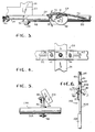
- Fig. 5 is an enlarged side elevational view of the connecting linkage which interconnects the pair of transponder reader arms as shown on the right of Fig. 1 and which carries the transponder reader; and
- Fig. 6 is an enlarged horizontal cross-sectional view taken along line 6-6 of Fig. 1 showing an alternate embodiment of the transponder reader arm assembly in accordance with the present invention.
- Referring now to the drawings, an automatic
animal feeding unit 10 adapted for feeding dairy animals such ascows 12, broadly includes a pair of transponderreader arm assemblies feed car 16 which is movable along a path defined by anoverhead rail 18. Each cow wears atransponder 20 which emits a radio signal identifying theindividual cow 12. Theanimal feeding unit 10 normally operates in a feeding barn where thecows 12 stand betweenstanchions 22 and feed from thefeed car 16 is deposited on the floor or feed table 24 for consumption by thecow 12 at each respective stall. - In greater detail, transponder
reader arm assemblies mounting bracket 26, at least one pivotally mountedtransponder reader arm 28 and atransponder reader 30. As shown in Fig. 1, themounting bracket 26 may carry opposite, outwardly extendingtransponder reader arms 28A and 28B so that two rows ofcows 12 may be serviced by asingle feed car 16. - The
mounting bracket 26 includes structure enabling eachtransponder reader arm 28 to be adjusted vertically and horizontally outwardly according to the particular configuration of the barn in which they are used. This structure onmounting bracket 26 includes aframe 32 secured to thefeed car 16 by welding, bolts or the like and a pair of downwardly extendinglegs reader arm assemblies - Referring now to Figure 4, the adjusting structure associated with the
mounting bracket 26 may be seen in greater detail.Frame 32 is provided with a pair ofelongated slots feed car 16 for eachleg clamp 42 is slidably mounted to theframe 32 by a pair ofadjustment bolts 44 secured by corresponding nuts. Theclamp 42 is provided with an clamping bolt 46 which holds one of thelegs clamp 42 and theframe 32. The clamping bolt 46 is threadably inserted into theclamp 42 so that it may be loosened to permit vertical adjustment of the leg held thereby. Similarly,adjustment bolts 44 may be loosened to permit shifting of the arm in a transverse direction relative to the path of thefeed car 16. - As may be seen in Figure 1,
legs transponder reader arms 28 thereto. The transponder reader arms shown as 28A and 28B are similarly mounted tolegs arm 28A and 28B. Eacharm 28 includes first and second members referred to asinboard end 48 anddistal end 50.Inboard end 48 includes abearing 52 havingfinger 54 extending normally inboard therefrom. Abolt 56, threadably coupled tonut 58, extends through bearing 52 and mountstransponder reader arm 28 to flange 60 which is welded or otherwise secured to one oflegs -
Arm 28 is biased to a normally outwardly extending orientation in a direction transverse to the path of thefeed car 16 bycoil spring 62.Coil spring 62 is connected tofinger 54 and to a tensioner 64 adjustable alongslot 66 inflange 60 as shown in Figures 1, 2 and 6. As shown in the drawings,arms 28 are pivotal in a generally horizontal plane by the pivoting action provided byinboard end 48 aboutbolt 56. - In addition,
transponder reader arms 28 include structure enablingdistal end 50 to pivot in a generally vertical plane relative toinboard end 48. As shown in Figure 3,inboard end 48 is separate fromdistal end 50 but are connected bycantilever spring 68. The biasing force applied by cantilever spring is transmitted alongreach 70 which is inserted throughdistal end 50. Theproximate portion 72 ofcantilever spring 68 is provided with an eye 74 for adjustable connection tospring mount 76 connected toinboard end 48.Spring mount 76 is generally arcuate in configuration and is slotted in a vertical plane therealong to permit varying the basing force supplied bycantilever spring 68.Cantilever spring 68 is held in place bybolt 78 which passes through frontplate 80 and abushing 81 carryingspring 68.Bolt 78 passes through the geometric center ofcantilever spring 68,bushing 81 and throughdistal end 50 before passing throughbackplate 82 and is secured by a lock nut.Cantilever spring 68 serves to limit bouncing of thedistal end 50 following displacement upon engagement with an obstacle and subsequent release. The frontplate 80 and thebackplate 82 hold the cantilever spring in position againstdistal end 50 and substantially limit its pivoting to a vertical plane oriented transversely to the path of the feed car. As may be seen in Figure 1, eachdistal end 50 includes a riser portion 83 which serves to place thetransponder reader 30 in close proximity to thetransponder 20 worn by the cow. - The transponder
reader arm assembly 14A is shown in Figure 2 which includes a pair of paralleltransponder reader arms transponder reader arms U-shaped connecting linkage 84 which extends throughreceivers 86 and 86' to enablearms linkage 84. Acrosspin 88 holds connectinglinkage 84 in place but allows connectinglinkage 84 to pivot relative toarms linkage 84, and thus thetransponder reader 30, is oriented continuously outwardly in the same direction which preferably is parallel to the path of thefeed car 16. As shown in Figure 5, thetransponder reader 30 includes aback mount 88 which couplestransponder reader 30 to connectinglinkage 84. - In the embodiment illustrated by transponder
reader arm assembly 14B, a single transponder reader arm 28B carries atransponder reader 30 at itsdistal end 50. Thetransponder reader 30 as shown in Figure 6 may be secured to thedistal end 50 by any conventional means such as theback mount 88 shown in Figure 5 but expanded to fit the arm 28B. The arm 28B is in all other respects identical toarm 28A and is free to pivot horizontally and is provided with a distal end which is free to pivot vertically just as inarm 28A. - In operation, the animal feeding unit travels along a rail or rails suspended from the ceiling of the dairy barn. The
rail 18 as shown in Figure 1 is oriented into the drawing page, and thus thetransponder reader arms 28A and 28B extend outwardly therefrom in a direction transverse to the path of travel of thefeed car 16. - The
clamp 42 may be shifted sideways withinslots transponder reader arms 28 corresponding to the configuration of the dimensions of the dairy barn, and thelegs transponder reader 30 relative to thecow 12. Of course, eachtransponder reader 30 is electronically coupled by acable 90 to the computer carrying the identifier data base for enabling the transponder reader to communicate with the feed car for delivering the proper ration to each cow. - After the feed car is charged with the desired nutrient components such as hay, soybean meal, silage, corn, vitamins and minerals and the like, the
feeding unit 10 begins to move along the path defined byrail 18. Upon reaching thefirst stanchion 22, the feed car may deposit a "teaser" ration to draw the cow's head down to place thetransponder 20 in close proximity to thetransponder reader 30. Thetransponder reader 30 then reads the signal emitted by the transponder and communicates it to the feed car for supplying the desired ration to thecow 12. - The transponder reader arm assembly 14 hereof is especially useful in a dairy barn because a
cow 12 may have her head down and in the way of thetransponder 30. The transponder reader arm assembly hereof is free to pivot out of the way of the cow or other obstruction, with the coil spring serving to return the arm to its desired, outwardly extending orientation. Thecoil spring 62 is positioned and tensioned by tensioner 64 so that the arm will not swing wildly to "slap" a cow and thus make her fearful of thefeeding unit 10 and thus impair her productivity. As shown in phantom in both Figure 2 and Figure 6, thearms 28A and 28B are free to pivot horizontally to allow thefeeding unit 10 to move past acow 12 or other obstacle in the way of the arms without harm to the obstacle or damage to the arms. - Yet further, the
distal end 50 of each of thearms 28A and 28B is free to pivot vertically in the event acow 12 were to step on thetransponder reader 30 or other vertical force is applied to thearm 28. Thecantilever spring 68 yields in response to such vertical force and returns thedistal end 50 of the arm to the original, desired, outwardly extending position as shown in solid lines in Figure 1. Thespring 68 also serves to prevent "bouncing" or excessive oscillation of thedistal end 50 when the displacing force is removed, and may be adjusted in tension alongspring mount 76 should increased biasing force be necessary.
Claims (15)
- A transponder reader arm assembly in combination with a feed car (16), the feed car being movable along a path for feeding livestock in response to signals sent by individual transponders associated with members (12) of the livestock, the transponder reader arm assembly (14A; 14B) comprising an arm (28) mounted to said feed car to extend in a transverse orientation relative to the path of said feed car, and a transponder reader (30) mounted adjacent an end of the arm remote from the feed car for the car to dispense feed to the members of the livestock in response to signals received by said transponder reader from said individual transponders, characterised in that the transponder arm (28) is coupled to the feed car by a pivot mechanism allowing pivotal movement of the arm relative to the feed car and including a device (62;68) to bias the arm to the transverse orientation.
- A transponder reader arm assembly as set forth in claim 1 wherein the biasing device (62;68) biases the arm (28) to a centred position wherein the arm extends in the transverse orientation, the arm being pivotable in opposite directions from said centred position.
- A transponder reader arm assembly as set forth in claim 1 or 2, wherein said arm (28) is substantially perpendicular to the path of said car (16) in the transverse orientation thereof.
- A transponder reader arm assembly as set forth in claim 1,2 or 3 therein said arm (28) is pivotable about a generally vertical axis.
- A transponder reader arm assembly as set forth in any one of claims 1 to 4, wherein said arm assembly is mounted to the feed car (16) by means (26) enabling the vertical height of said arm (28) to be adjusted relative to said car.
- A transponder reader arm assembly as set forth in any one of claims 1 to 5 wherein said arm (28) is mounted to the feed car (16) by means (26) enabling the horizontal distance of said remote end of the arm from said feed car to be adjusted.
- A transponder reader arm assembly as set forth in any one of claims 1 to 6, wherein said arm (28) is pivotable in a generally horizontal plane.
- A transponder reader arm assembly as set forth in any one of claims 1 to 6, wherein said arm (28) is pivotable in a generally vertical plane.
- A transponder reader arm assembly according to any one of claims 1 to 6, wherein said arm (28) includes a first member (48) and a second member (50), the first member (48) being mounted to the feed car (16) by the pivot mechanism to allow the arm to pivot in a generally horizontal plane, and the second member (50) being coupled to the first member (48) for pivotable movement of the second member in a generally vertical plane.
- A transponder reader arm assembly as set forth in claim 9 including biasing means (68) acting between the first and second arm members (48;50) to bias the second member (50) into alignment with said first member (48).
- A transponder reader arm assembly as set forth in claim 10, wherein said biasing means (68) is adjustably connected to said first arm member (48) for varying the biasing force exerted thereby on the second arm member (50).
- A transponder reader arm assembly as set forth in any one of claims 1 to 11, wherein said transponder reader (30) is mounted in substantial alignment with said remote end of the arm (28).
- A transponder reader arm assembly as set forth in any one of claims 1 to 12, including a second arm (28A') connected to said feed car (16) and spaced from the first arm (28A), and means (84) interconnecting the first and second arms adjacent the ends thereof remote from the feed car to maintain the first and second arms in parallel orientation during pivotal movement of the first arm.
- A transponder reader arm assembly as set forth in claim 13, wherein said transponder reader (30) is carried on the interconnecting means (84) intermediate said first and second arms (28A;28A').
- A transponder reader arm assembly according to claim 12,13 or 14, wherein the second arm (28A') is of substantially the same form as the first arm (28A').
Applications Claiming Priority (3)
| Application Number | Priority Date | Filing Date | Title |
|---|---|---|---|
| US07/553,522 US5088447A (en) | 1990-07-16 | 1990-07-16 | Transponder reader arm assembly |
| US553522 | 1990-07-16 | ||
| PCT/US1991/004901 WO1992001371A1 (en) | 1990-07-16 | 1991-07-11 | Transponder reader arm assembly |
Publications (3)
| Publication Number | Publication Date |
|---|---|
| EP0552164A1 EP0552164A1 (en) | 1993-07-28 |
| EP0552164A4 EP0552164A4 (en) | 1993-12-08 |
| EP0552164B1 true EP0552164B1 (en) | 1997-05-28 |
Family
ID=24209733
Family Applications (1)
| Application Number | Title | Priority Date | Filing Date |
|---|---|---|---|
| EP91914205A Expired - Lifetime EP0552164B1 (en) | 1990-07-16 | 1991-07-11 | Transponder reader arm assembly |
Country Status (4)
| Country | Link |
|---|---|
| US (1) | US5088447A (en) |
| EP (1) | EP0552164B1 (en) |
| DE (1) | DE69126313D1 (en) |
| WO (1) | WO1992001371A1 (en) |
Families Citing this family (33)
| Publication number | Priority date | Publication date | Assignee | Title |
|---|---|---|---|---|
| US5172121A (en) * | 1991-04-30 | 1992-12-15 | Consolidated Rail Corp. | System for automatic identification of rail cars |
| CA2185702A1 (en) * | 1995-01-17 | 1996-07-25 | William T. Smeester | Automatic animal feeder and insecticide sprayer |
| US6899791B2 (en) | 1997-08-08 | 2005-05-31 | Andritz Inc. | Method of pretreating lignocellulose fiber-containing material in a pulp refining process |
| US7228816B2 (en) * | 2004-03-22 | 2007-06-12 | Robert Michael Turner | Animal feeding device and method |
| US9784041B2 (en) * | 2004-04-15 | 2017-10-10 | National Oilwell Varco L.P. | Drilling rig riser identification apparatus |
| US20050284382A1 (en) * | 2004-05-27 | 2005-12-29 | George Stantchev | Method and apparatus for selectively feeding animals |
| SE527691C2 (en) * | 2004-10-01 | 2006-05-09 | Delaval Holding Ab | Apparatus and method for automatic milking of animals |
| JP4413212B2 (en) * | 2006-09-15 | 2010-02-10 | 日本テキサス・インスツルメンツ株式会社 | Livestock management system and cage |
| US7685966B2 (en) * | 2006-11-03 | 2010-03-30 | Goehring Heidi L | Lidded pet dish |
| US9161511B2 (en) * | 2010-07-06 | 2015-10-20 | Technologies Holdings Corp. | Automated rotary milking system |
| US8707905B2 (en) | 2010-08-31 | 2014-04-29 | Technologies Holdings Corp. | Automated system for applying disinfectant to the teats of dairy livestock |
| US9149018B2 (en) | 2010-08-31 | 2015-10-06 | Technologies Holdings Corp. | System and method for determining whether to operate a robot in conjunction with a rotary milking platform based on detection of a milking claw |
| US10111401B2 (en) | 2010-08-31 | 2018-10-30 | Technologies Holdings Corp. | System and method for determining whether to operate a robot in conjunction with a rotary parlor |
| US8800487B2 (en) | 2010-08-31 | 2014-08-12 | Technologies Holdings Corp. | System and method for controlling the position of a robot carriage based on the position of a milking stall of an adjacent rotary milking platform |
| US9215861B2 (en) | 2011-04-28 | 2015-12-22 | Technologies Holdings Corp. | Milking box with robotic attacher and backplane for tracking movements of a dairy animal |
| US8683946B2 (en) | 2011-04-28 | 2014-04-01 | Technologies Holdings Corp. | System and method of attaching cups to a dairy animal |
| US8671885B2 (en) | 2011-04-28 | 2014-03-18 | Technologies Holdings Corp. | Vision system for robotic attacher |
| US9049843B2 (en) | 2011-04-28 | 2015-06-09 | Technologies Holdings Corp. | Milking box with a robotic attacher having a three-dimensional range of motion |
| US10357015B2 (en) | 2011-04-28 | 2019-07-23 | Technologies Holdings Corp. | Robotic arm with double grabber and method of operation |
| US9161512B2 (en) | 2011-04-28 | 2015-10-20 | Technologies Holdings Corp. | Milking box with robotic attacher comprising an arm that pivots, rotates, and grips |
| US10127446B2 (en) | 2011-04-28 | 2018-11-13 | Technologies Holdings Corp. | System and method for filtering data captured by a 2D camera |
| US9265227B2 (en) | 2011-04-28 | 2016-02-23 | Technologies Holdings Corp. | System and method for improved attachment of a cup to a dairy animal |
| US9681634B2 (en) | 2011-04-28 | 2017-06-20 | Technologies Holdings Corp. | System and method to determine a teat position using edge detection in rear images of a livestock from two cameras |
| US9107379B2 (en) | 2011-04-28 | 2015-08-18 | Technologies Holdings Corp. | Arrangement of milking box stalls |
| US9043988B2 (en) | 2011-04-28 | 2015-06-02 | Technologies Holdings Corp. | Milking box with storage area for teat cups |
| US8885891B2 (en) | 2011-04-28 | 2014-11-11 | Technologies Holdings Corp. | System and method for analyzing data captured by a three-dimensional camera |
| US9058657B2 (en) | 2011-04-28 | 2015-06-16 | Technologies Holdings Corp. | System and method for filtering data captured by a 3D camera |
| US8903129B2 (en) | 2011-04-28 | 2014-12-02 | Technologies Holdings Corp. | System and method for filtering data captured by a 2D camera |
| US8746176B2 (en) | 2011-04-28 | 2014-06-10 | Technologies Holdings Corp. | System and method of attaching a cup to a dairy animal according to a sequence |
| US9357744B2 (en) * | 2011-04-28 | 2016-06-07 | Technologies Holdings Corp. | Cleaning system for a milking box stall |
| US9258975B2 (en) | 2011-04-28 | 2016-02-16 | Technologies Holdings Corp. | Milking box with robotic attacher and vision system |
| US9107378B2 (en) | 2011-04-28 | 2015-08-18 | Technologies Holdings Corp. | Milking box with robotic attacher |
| CN112021193B (en) * | 2020-09-04 | 2022-04-15 | 重庆市天友乳业股份有限公司 | Breed and throw feeder with fodder |
Family Cites Families (14)
| Publication number | Priority date | Publication date | Assignee | Title |
|---|---|---|---|---|
| US2578863A (en) * | 1949-02-11 | 1951-12-18 | Seift & Company | Individual poultry feeding unit |
| GB1242385A (en) * | 1967-06-20 | 1971-08-11 | John Edward Moffitt | Identification system |
| SU378208A1 (en) * | 1971-02-15 | 1973-04-18 | FEEDER FEED | |
| SU467727A1 (en) * | 1972-01-26 | 1975-04-25 | Головное Специальное Конструкторское Бюро По Комплекусу Машин Для Ферм Крупного Рогатого Скота | Indicator to determine the location of the animal |
| US4129855A (en) * | 1977-07-15 | 1978-12-12 | Rodrian J | Animal identification system |
| US4313397A (en) * | 1980-01-22 | 1982-02-02 | Markum Donnie D | Apparatus for motivating animals to move |
| US4463353A (en) * | 1981-08-17 | 1984-07-31 | Ralston Purina Company | Animal feeding and monitoring system |
| US4426955A (en) * | 1981-12-16 | 1984-01-24 | Optek, Inc. | Identification and animal feeding apparatus |
| SU1168156A1 (en) * | 1984-02-27 | 1985-07-23 | Саратовский Ордена "Знак Почета" Институт Механизации Сельского Хозяйства Им.М.И.Калинина | Feed distributor |
| US4617876A (en) * | 1984-11-28 | 1986-10-21 | Hayes Norman J | Animal identification and control system |
| US4712511A (en) * | 1985-08-15 | 1987-12-15 | Zamzow Donald D | Programmed mix and delivery system |
| US4655170A (en) * | 1985-12-02 | 1987-04-07 | Dasilva Daniel R | Animal identification feed control system |
| FR2595202B3 (en) * | 1986-03-06 | 1988-07-15 | Lerin Patrick | DEVICE FOR THE DISPENSING OF FLOURAL OR GRANULAR PRODUCTS AND, IN PARTICULAR, FOOD FOR ANIMALS |
| JPS6364863A (en) * | 1986-09-05 | 1988-03-23 | 株式会社東芝 | Conveyance device |
-
1990
- 1990-07-16 US US07/553,522 patent/US5088447A/en not_active Expired - Lifetime
-
1991
- 1991-07-11 WO PCT/US1991/004901 patent/WO1992001371A1/en not_active Ceased
- 1991-07-11 DE DE69126313T patent/DE69126313D1/en not_active Expired - Lifetime
- 1991-07-11 EP EP91914205A patent/EP0552164B1/en not_active Expired - Lifetime
Also Published As
| Publication number | Publication date |
|---|---|
| DE69126313D1 (en) | 1997-07-03 |
| WO1992001371A1 (en) | 1992-02-06 |
| EP0552164A1 (en) | 1993-07-28 |
| US5088447A (en) | 1992-02-18 |
| EP0552164A4 (en) | 1993-12-08 |
Similar Documents
| Publication | Publication Date | Title |
|---|---|---|
| US5088447A (en) | Transponder reader arm assembly | |
| EP0565189B1 (en) | A construction for automatically milking animals | |
| EP0194729B1 (en) | Implement for milking animals | |
| EP0634097B1 (en) | A construction for automatically milking animals | |
| US5909716A (en) | Apparatus for and a method of milking animals | |
| NL9200091A (en) | MILK MACHINE. | |
| EP0880889B1 (en) | An implement for milking animals | |
| NL9401113A (en) | Construction with a device for automatic milking of animals. | |
| NL9401069A (en) | Device for automatic milking of animals. | |
| US5826536A (en) | Construction including an implement for milking animals | |
| EP1419689A3 (en) | An implement for automatically feeding animals | |
| EA009146B1 (en) | Device and method for automatic milking of animals | |
| NL9401033A (en) | Construction with a device for automatic milking of animals. | |
| AU684502B2 (en) | A construction for automatically milking animals | |
| US20100192860A1 (en) | Milking facility and method for milking therein | |
| NZ328177A (en) | Milking machine with teat cups connected to robot arm by flexible cord | |
| EP0638231B1 (en) | A construction for automatically milking animals | |
| EP0231182A1 (en) | Method and apparatus for feeding | |
| EP0886466B1 (en) | A construction including an implement for automatically milking animals | |
| EP0351400A1 (en) | Feeding station for loose going animals | |
| EP0638232B1 (en) | A construction for automatically milking animals | |
| US4961401A (en) | Manger divider | |
| NL9200097A (en) | Automatic control and monitoring system for milking parlour | |
| NL9200095A (en) | Automatic control and monitoring system for milking parlour | |
| NL9200096A (en) | Automatic control and monitoring system for milking parlour |
Legal Events
| Date | Code | Title | Description |
|---|---|---|---|
| PUAI | Public reference made under article 153(3) epc to a published international application that has entered the european phase |
Free format text: ORIGINAL CODE: 0009012 |
|
| 17P | Request for examination filed |
Effective date: 19930420 |
|
| AK | Designated contracting states |
Kind code of ref document: A1 Designated state(s): DE FR GB NL SE |
|
| A4 | Supplementary search report drawn up and despatched | ||
| AK | Designated contracting states |
Kind code of ref document: A4 Designated state(s): DE FR GB NL SE |
|
| 17Q | First examination report despatched |
Effective date: 19951107 |
|
| GRAG | Despatch of communication of intention to grant |
Free format text: ORIGINAL CODE: EPIDOS AGRA |
|
| GRAH | Despatch of communication of intention to grant a patent |
Free format text: ORIGINAL CODE: EPIDOS IGRA |
|
| GRAH | Despatch of communication of intention to grant a patent |
Free format text: ORIGINAL CODE: EPIDOS IGRA |
|
| GRAA | (expected) grant |
Free format text: ORIGINAL CODE: 0009210 |
|
| AK | Designated contracting states |
Kind code of ref document: B1 Designated state(s): DE FR GB NL SE |
|
| PG25 | Lapsed in a contracting state [announced via postgrant information from national office to epo] |
Ref country code: FR Effective date: 19970528 |
|
| REF | Corresponds to: |
Ref document number: 69126313 Country of ref document: DE Date of ref document: 19970703 |
|
| PG25 | Lapsed in a contracting state [announced via postgrant information from national office to epo] |
Ref country code: SE Effective date: 19970828 Ref country code: GB Free format text: LAPSE BECAUSE OF NON-PAYMENT OF DUE FEES Effective date: 19970828 |
|
| PG25 | Lapsed in a contracting state [announced via postgrant information from national office to epo] |
Ref country code: DE Effective date: 19970829 |
|
| EN | Fr: translation not filed | ||
| PLBE | No opposition filed within time limit |
Free format text: ORIGINAL CODE: 0009261 |
|
| STAA | Information on the status of an ep patent application or granted ep patent |
Free format text: STATUS: NO OPPOSITION FILED WITHIN TIME LIMIT |
|
| GBPC | Gb: european patent ceased through non-payment of renewal fee |
Effective date: 19970828 |
|
| 26N | No opposition filed | ||
| PGFP | Annual fee paid to national office [announced via postgrant information from national office to epo] |
Ref country code: NL Payment date: 20010621 Year of fee payment: 11 |
|
| PG25 | Lapsed in a contracting state [announced via postgrant information from national office to epo] |
Ref country code: NL Free format text: LAPSE BECAUSE OF NON-PAYMENT OF DUE FEES Effective date: 20030201 |
|
| NLV4 | Nl: lapsed or anulled due to non-payment of the annual fee |
Effective date: 20030201 |