EP0552123B1 - Rohrsteckverbindung und deren Abdichtung - Google Patents
Rohrsteckverbindung und deren Abdichtung Download PDFInfo
- Publication number
- EP0552123B1 EP0552123B1 EP93470001A EP93470001A EP0552123B1 EP 0552123 B1 EP0552123 B1 EP 0552123B1 EP 93470001 A EP93470001 A EP 93470001A EP 93470001 A EP93470001 A EP 93470001A EP 0552123 B1 EP0552123 B1 EP 0552123B1
- Authority
- EP
- European Patent Office
- Prior art keywords
- socket
- spigot
- seal
- elastomer
- joint according
- Prior art date
- Legal status (The legal status is an assumption and is not a legal conclusion. Google has not performed a legal analysis and makes no representation as to the accuracy of the status listed.)
- Expired - Lifetime
Links
Images

Classifications
-
- F—MECHANICAL ENGINEERING; LIGHTING; HEATING; WEAPONS; BLASTING
- F16—ENGINEERING ELEMENTS AND UNITS; GENERAL MEASURES FOR PRODUCING AND MAINTAINING EFFECTIVE FUNCTIONING OF MACHINES OR INSTALLATIONS; THERMAL INSULATION IN GENERAL
- F16L—PIPES; JOINTS OR FITTINGS FOR PIPES; SUPPORTS FOR PIPES, CABLES OR PROTECTIVE TUBING; MEANS FOR THERMAL INSULATION IN GENERAL
- F16L37/00—Couplings of the quick-acting type
- F16L37/08—Couplings of the quick-acting type in which the connection between abutting or axially overlapping ends is maintained by locking members
- F16L37/084—Couplings of the quick-acting type in which the connection between abutting or axially overlapping ends is maintained by locking members combined with automatic locking
- F16L37/0845—Couplings of the quick-acting type in which the connection between abutting or axially overlapping ends is maintained by locking members combined with automatic locking by means of retaining members associated with the packing member
Definitions
- the present invention relates to a joint fitting between pipes of the type comprising a male end pressed into a socket and a seal compressed radially therebetween, the seal comprising an annular elastomer body provided, on the inlet side. of the socket, an external projecting anchor heel housed in an anchoring groove of the socket, and a metal ring for hooking on the male end, embedded in the elastomer.
- the invention applies to the laying of pipes, in particular ductile iron, conveying fluids under pressure.
- the object of the invention is to provide a solution fulfilling all of the above conditions in a more satisfactory manner than the existing solutions.
- the subject of the invention is a socket joint of the aforementioned type, characterized in that it comprises support members embedded in the elastomer of the anchor heel of the seal and having externally a shape combined with that of the groove for anchoring the socket, these support members and the attachment ring having cooperating ramps with at least approximately linear profile, inclined relative to the axis of the joint .
- the subject of the invention is also a gasket with radial compression and a metal hooking ring for a socket joint as defined above.
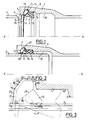
- FIG. 1 shows the socket 1 of a first pipe and the male end 2, with an externally chamfered end at 3, of a second pipe, as well as a seal 4 with radial compression and with inserts lock intended to achieve both sealing and locking between the two pipes.
- the two pipes can in particular be made of ductile iron.
- the socket 1 comprises a guide flange 5, the inlet of which is chamfered at 6, then going towards the bottom of the socket, an anchoring groove 7, an annular recess 8 of shallower depth, an annular flange 9 slightly radial projection, and a terminal housing 10.
- the lining 4 consists of a mass of elastomer overmolded on a ring of pairs of inserts made of rigid material, in particular metallic, each pair comprising a bearing insert 11 and a hooking insert 12 internally toothed.
- the lining defines a front body 13, intended to be compressed radially between the male end and the bottom of the recess 8 and, at the rear end (that is to say located on the entry side of the fitting) of this body, an external anchoring heel 14 and an internal sealing lip 15 serving to avoid the introduction of aggressive or corrosive external elements into the locked area.
- Each pair of inserts 11, 12 is contained in the same radial half-plane of the lining, and these pairs are regularly distributed around the periphery of the latter.
- the assembly of the seal is carried out by simple axial insertion of the male end into the socket. This action folds the lip 15 forwards, then radially pushes the inserts 11 and 12, the latter sliding along the inserts 11, and compresses the body 13 radially. This results in the configuration of FIG. 2, where the end of the male end is, with a large radial clearance, in the recess 10, where the inserts 11 are blocked in the rear outer part of the groove 7 and / or the inserts 12 are both in contact with the latter and , by their teeth 16, in contact with the male end.
- the groove 7 of the socket successively has, from the flange 5, a wall 17 approximately radial and slightly inclined forward, a wall 18 markedly more inclined, about 45 °, a cylindrical bottom 19, and a front wall 20 approximately radial and slightly inclined towards the front.
- Each insert 11 has: towards the rear and outside three successive surfaces 21 to 23 respectively conjugated with surfaces 17 to 19; an inner surface 24 parallel to the axis XX of the fitting, which is substantially the axis of the male end and therefore of the joint, this surface 24 being connected by a rounding to the inner end of the surface 21; a surface 25 roughly parallel to the surface 20 and joining by a rounding to the front end of the surface 23; and a flat support ramp 26, the inclination of which, upwards and downwards, is between approximately 20 and 40 ° relative to the axis XX of the joint, this ramp connecting the front end of the surface 24 at the lower end of the surface 25, the connections being made by rounding.
- Each insert 12 has a roughly quadrangular shape, with a planar outer and rear surface 27 and, opposite to this, an inner hooking surface defining the three teeth 16 of the insert.
- the surface 27 forms a support ramp intended to cooperate with the ramp 26 of the associated insert 11.
- the outer part of the surface 27 is located opposite the inner part of the surface 26. The same is true when the lining is at rest.
- FIG. 3 thus illustrates the positions of an insert 12 corresponding to a diameter maximum of the male end (in solid line) and a minimum diameter of this male end (in dashed line).
- the three teeth 16 are machined so that their points are aligned on a straight line which, when the surfaces 27 and 26 cooperate, is parallel to the axis X-X of the socket.
- the three teeth simultaneously attack this male end, and, when the latter recoils, the contact pressure is distributed between them uniformly.
- the seals described above can accept angular deviations of the male end relative to the fitting of up to approximately 5 °.
- each tooth 16 of each insert 12 has a determined orientation, perpendicular to the surface 26, which prevents pivoting. inserts 12 which risk perforating the male end.
- the inclination of the ramps 26 relative to the axis of the socket is preferably chosen between approximately 20 and 40 °, as indicated above. In fact, below 20 °, the diametrical tolerances allowed for the male end are very low, and above 40 °, the inserts 12 do not hook well on the male end and, consequently, the locking is little reliable.
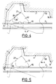
- FIGs 4 to 7 illustrate various variants of the seal in Figures 1 to 3.
- the surfaces 27 are slightly curved, which allows greater angular deviations of the male end, which can go up to about 10 °.
- the pressures exerted on the three teeth are different from each other during the retraction of the male end, since the reaction forces all start from the single point of contact 28 between the surfaces 26 and 27.
- the same remarks apply to another variant, not shown, where it is the surfaces 26 which are slightly domed.
- Figure 5 differs from that of Figure 3 only in that the middle tooth 16 is radially recessed from the two end teeth. This facilitates the attachment of the inserts 12 on the male end, because, for the same effort, the initial pressures, acting only on two teeth instead of three, are higher. On the other hand, when the recoil of the male end is finished, the pressures are balanced between the three teeth.
- the inserts 11 and / or 12 can be electrically insulated to eliminate any path of electrical conduction between the two pipes.
Landscapes
- General Engineering & Computer Science (AREA)
- Engineering & Computer Science (AREA)
- Mechanical Engineering (AREA)
- Joints With Sleeves (AREA)
- Joints With Pressure Members (AREA)
- Gasket Seals (AREA)
- Quick-Acting Or Multi-Walled Pipe Joints (AREA)
- Non-Disconnectible Joints And Screw-Threaded Joints (AREA)
- Seal Device For Vehicle (AREA)
- Pharmaceuticals Containing Other Organic And Inorganic Compounds (AREA)
- Medicines Containing Material From Animals Or Micro-Organisms (AREA)
- Pens And Brushes (AREA)
- Solid-Sorbent Or Filter-Aiding Compositions (AREA)
- Mutual Connection Of Rods And Tubes (AREA)
- Sealing Material Composition (AREA)
- Joining Of Building Structures In Genera (AREA)
- Resistance Heating (AREA)
- Reciprocating Pumps (AREA)
- Reinforcement Elements For Buildings (AREA)
- Superconductors And Manufacturing Methods Therefor (AREA)
- Earth Drilling (AREA)
- Inert Electrodes (AREA)
- Basic Packing Technique (AREA)
- Steering Control In Accordance With Driving Conditions (AREA)
- Forms Removed On Construction Sites Or Auxiliary Members Thereof (AREA)
Claims (8)
- Rohrsteckverbindung, mit einem männlichen Endstück oder Einsteckende (2), das in eine Aufnahme (1) eingesteckt ist, und einer Dichtungsgarnitur (4), die radial zwischen ihnen komprimiert ist, wobei die Garnitur einen ringförmigen Körper (13) aus Elastomer, der auf der Seite des Eingangs der Aufnahme mit einem Verankerungsabsatz (14) versehen ist, der nach außen vorspringt und in einer Verankerungskerbe (7) der Aufnahme aufgenommen ist, und einen metallischen Anhängkranz (12) auf dem Einsteckende aufweist, das in den Elastomer eingetaucht ist, dadurch gekennzeichnet, daß sie Andrückorgane (11) aufweist, die in den Elastomer des Verankerungsabsatzes (14) der Dichtungsgarnitur (4) eingetaucht sind, und außen eine Form (21, 22, 23) aufweist, die jener (17, 18, 19) der Verankerungskerbe (7) der Aufnahme (1) folgt, wobei diese Andrückorgane (11) und der Verankerungskranz (12) zusammenwirkende Rampen (26, 27) mit einem wenigstens ungefähr linearen Profil aufweisen, die bezüglich der Achse (X-X) der Verbindung geneigt sind.
- Rohrsteckverbindung nach Anspruch 1, dadurch gekennzeichnet, daß die Andrückorgane (11) und/oder der Verankerungskranz (12) aus einer Reihe von Einsätzen aus starrem Material gebildet sind, die am Umfang der Verbindung verteilt angeordnet sind.
- Rohrsteckverbindung nach Anspruch 1 oder 2, dadurch gekennzeichnet, daß in einer jeder radialen Ebene, in der sie existiert, der Anhängkranz (12) mehrere Zähne (16) aufweist.
- Rohrsteckverbindung nach Anspruch 3, dadurch gekennzeichnet, daß die Spitzen aller Zähne (16) auf einer Linie parallel zur Achse (X-X) der Aufnahme ausgerichtet sind, oder ausgerichtet werden können, wenn die zusammenwirkenden Rampen (26, 27) sich in gegenseitigem Andruck befinden.
- Rohrsteckverbindung nach Anspruch 3, dadurch gekennzeichnet, daß die Spitze wenigstens eines der Mittenzähne (16) radial bezüglich der anderen Zähne (16) versetzt ist.
- Rohrsteckverbindung nach Anspruch 3, dadurch gekennzeichnet, daß die Spitze wenigstens eines Endzahnes (16) bezüglich der anderen Zähne (16) radial versetzt angeordnet ist.
- Rohrsteckverbindung nach einem der Ansprüche 1 bis 6, daduch gekennzeichnet, daß die Neigung oder die mittlere Neigung der zusammenwirkenden Rampen (26, 27) zwischen ungefähr 20° und ungefähr 40° bezüglich der Achse (X-X) der Aufnahme beträgt.
- Dichtungsgarnitur (4) mit radialer Komprimierung und metallischen Anhängkranz (12) für eine Rohrsteckverbindung nach einem der Ansprüche 1 bis 7, wobei die Garnitur einen ringförmigen Körper (13) aus Elastomer aufweist, der mit einem nach außen vorspringenden Verankerungsabsatz (14), einem metallischen Anhängkranz (12), der in dem Elastomer eingetaucht ist, und mit Andrückorganen (11) versehen ist, die in den Elastomer des Verankerungsabsatzes (14) der Dichtungsgarnitur (4) eingetaucht sind, wobei diese Andrück- oder Anlageorgane (11) und der Anhängkranz (12) zusammenwirkende Rampen (26, 27) mit einem wenigstens ungefähr linearem Profil aufweisen, die bezüglich der Achse (X-X) der Garnitur geneigt sind.
Applications Claiming Priority (2)
| Application Number | Priority Date | Filing Date | Title |
|---|---|---|---|
| FR9200262A FR2686140B1 (fr) | 1992-01-13 | 1992-01-13 | Joint a emboitement entre tuyaux et garniture d'etancheite pour un tel joint. |
| FR9200262 | 1992-01-13 |
Publications (2)
| Publication Number | Publication Date |
|---|---|
| EP0552123A1 EP0552123A1 (de) | 1993-07-21 |
| EP0552123B1 true EP0552123B1 (de) | 1995-09-13 |
Family
ID=9425567
Family Applications (1)
| Application Number | Title | Priority Date | Filing Date |
|---|---|---|---|
| EP93470001A Expired - Lifetime EP0552123B1 (de) | 1992-01-13 | 1993-01-11 | Rohrsteckverbindung und deren Abdichtung |
Country Status (21)
| Country | Link |
|---|---|
| US (1) | US5360218A (de) |
| EP (1) | EP0552123B1 (de) |
| JP (1) | JPH0737838B2 (de) |
| AT (1) | ATE127893T1 (de) |
| AU (1) | AU672766B2 (de) |
| BR (1) | BR9300116A (de) |
| CA (1) | CA2087045C (de) |
| DE (1) | DE69300458T2 (de) |
| DK (1) | DK0552123T3 (de) |
| EE (1) | EE02965B1 (de) |
| EG (1) | EG19788A (de) |
| ES (1) | ES2070108T3 (de) |
| FI (1) | FI930136A (de) |
| FR (1) | FR2686140B1 (de) |
| GR (1) | GR3017417T3 (de) |
| LT (1) | LT3060B (de) |
| LV (1) | LV10667B (de) |
| MX (1) | MX9300113A (de) |
| NO (1) | NO930076L (de) |
| RU (1) | RU2080511C1 (de) |
| ZA (1) | ZA9210104B (de) |
Families Citing this family (46)
| Publication number | Priority date | Publication date | Assignee | Title |
|---|---|---|---|---|
| JP2576785Y2 (ja) * | 1993-02-22 | 1998-07-16 | 矢崎総業株式会社 | 防水コネクタの嵌合構造 |
| FR2708077B1 (fr) * | 1993-07-23 | 1995-09-22 | Pont A Mousson | Insert de verrouillage électriquement isolant pour garniture d'étanchéité, garniture d'étanchéité correspondante, et procédé de fabrication de tels inserts. |
| US5845945A (en) * | 1993-10-07 | 1998-12-08 | Carstensen; Kenneth J. | Tubing interconnection system with different size snap ring grooves |
| NL1009734C2 (nl) * | 1998-07-24 | 2000-01-25 | Fischer Georg Waga Nv | Koppelinrichting en werkwijze voor de vervaardiging van een in een dergelijke koppelinrichting te gebruiken gripring. |
| NL1002514C2 (nl) | 1996-03-04 | 1997-09-05 | Fischer Georg Waga Nv | Koppelinrichting. |
| GB2346422B (en) * | 1999-02-02 | 2003-04-23 | Glynwed Pipe Systems Ltd | A pipe coupling |
| SE519239C2 (sv) * | 1999-05-31 | 2003-02-04 | Enebacken Skrea Ab | Tätningsanordning för avtätning av en av två mot varandra vända tätningsytor bildad fog |
| US6499744B1 (en) * | 2000-06-05 | 2002-12-31 | S&B Technical Products, Inc. | Pipe gasket with dual purpose tail |
| US7104573B2 (en) * | 2000-06-08 | 2006-09-12 | United States Pipe And Foundy Company, Llc | Energized restraining gasket for mechanical joints of pipes |
| US7108289B1 (en) | 2000-06-08 | 2006-09-19 | United States Pipe And Foundry Company, Llc | Restraining gasket for mechanical joints of pipes |
| FR2820191B1 (fr) * | 2001-02-01 | 2004-01-30 | Saint Gobain Pont A Mousson | Garniture d'etancheite pour assemblage d'elements tubulaires de circuits de fluide |
| US6688652B2 (en) * | 2001-12-12 | 2004-02-10 | U.S. Pipe And Foundry Company | Locking device and method for securing telescoped pipe |
| DE20305711U1 (de) * | 2003-04-09 | 2003-08-28 | Buderus Guss Gmbh | Zuggesicherte Muffenrohrverbindung |
| US20040232698A1 (en) * | 2003-05-19 | 2004-11-25 | Jim Jones | Self restraining gasket and pipe joint |
| US7125054B2 (en) * | 2003-05-19 | 2006-10-24 | S & B Technical Products, Inc. | Self restraining gasket and pipe joint |
| US7137653B2 (en) * | 2003-09-25 | 2006-11-21 | United States Pipe And Foundry Company, Llc | Centroidally twistable compression ring for pipe joints |
| US7410174B2 (en) * | 2004-03-04 | 2008-08-12 | S & B Technical Products, Inc. | Restraining mechanical joint gasket for ductile iron pipe |
| US20050275217A1 (en) * | 2004-04-02 | 2005-12-15 | Star Pipe Products Ltd. | Mechanical joint gripping gasket |
| US7207606B2 (en) * | 2004-04-19 | 2007-04-24 | United States Pipe And Foundry Company, Llc | Mechanical pipe joint, gasket, and method for restraining pipe spigots in mechanical pipe joint bell sockets |
| FR2875888B1 (fr) * | 2004-09-24 | 2006-12-01 | Saint Gobain Pam Sa | Garniture d'etancheite et assemblage correspondant |
| US7815225B2 (en) * | 2005-06-10 | 2010-10-19 | S & B Technical Products, Inc. | Self restrained ductile iron fitting |
| US8235427B2 (en) * | 2005-06-10 | 2012-08-07 | S & B Technical Products, Inc. | Self restrained ductile iron fitting |
| US20100078937A1 (en) * | 2005-06-10 | 2010-04-01 | S & B Technical Products, Inc. | Self Restrained Ductile Iron Fitting |
| US20080001401A1 (en) * | 2006-05-25 | 2008-01-03 | Guido Quesada | Method and apparatus for preventing overinsertion in plastic pipe systems |
| US20080018017A1 (en) * | 2006-07-21 | 2008-01-24 | Guido Quesada | Modified transition angle in belled pipe |
| FR2907877B1 (fr) * | 2006-10-31 | 2012-06-22 | Saint Gobain Pont A Mousson | Jonction tubulaire |
| US20090273184A1 (en) * | 2008-04-30 | 2009-11-05 | Michael Wright | Self restrained joint for ductile iron pipe and fittings |
| WO2010102017A1 (en) * | 2009-03-03 | 2010-09-10 | Mueller International, Inc. | Gasket for bell socket |
| MX344677B (es) | 2009-10-09 | 2017-01-04 | Mueller Int Llc * | Dispositivo sellador simplificado de baja fuerza de inserción capaz de auto-restringir y desviar junta. |
| US8857861B2 (en) | 2009-10-12 | 2014-10-14 | Mueller International, Llc | Self-restrained pipe joint system |
| WO2011149840A1 (en) | 2010-05-24 | 2011-12-01 | Mueller International, Llc | Simplified low insertion force sealing device capable of self restraint and joint deflection |
| WO2012027464A2 (en) | 2010-08-24 | 2012-03-01 | Mueller International, Llc. | Gasket for parabolic ramp self restraining bell joint |
| US8544851B2 (en) | 2010-08-24 | 2013-10-01 | Mueller International, Llc | Gasket for parabolic ramp self restraining bell joint |
| US8490273B1 (en) * | 2010-10-08 | 2013-07-23 | Mcwane Global | Pipe joint gasket and method of using same |
| FR2966554B1 (fr) * | 2010-10-26 | 2013-11-29 | Saint Gobain Pont A Mousson | Insert de verrouillage, garniture d'etancheite et assemblage correspondants |
| US9383049B2 (en) * | 2011-05-02 | 2016-07-05 | Cambridge Brass, Inc. | Universal coupling and parts therefor |
| DE102011082762A1 (de) | 2011-09-15 | 2013-03-21 | Airbus Operations Gmbh | Bewegliche Kupplung für eine Rohrleitung, Tankanordnung sowie Luft- oder Raumfahrzeug |
| AT511592B1 (de) * | 2011-09-19 | 2013-01-15 | E Hawle Armaturenwerke Gmbh | Rohrverbindungsvorrichtung und verfahren zu deren herstellung |
| US20140191504A1 (en) * | 2013-01-04 | 2014-07-10 | Yijun WU | PVC-Coated and Adaptive Pipe Coupling |
| WO2014186770A1 (en) * | 2013-05-16 | 2014-11-20 | Infra-Tect, Llc | Beveled insert for facilitating coupling pipes |
| CH711285B1 (de) * | 2015-07-01 | 2019-02-15 | Marktmanagement Wild Ag | Schubsicherung für die Verbindung eines ersten Rohrabschnitts mit Anschlussmuffe mit einem zweiten Rohrabschnitt mit einem Einsteckende. |
| US10352486B2 (en) * | 2015-12-24 | 2019-07-16 | American Cast Iron Pipe Company | Method of manufacturing a unitary gasket using two rubber materials of different hardness |
| US10400924B2 (en) | 2015-12-24 | 2019-09-03 | American Cast Iron Pipe Company | Pipe joint with low insertion load, improved retention and increased high pressure sealing ability gasket and method of manufacture thereof |
| US10648602B2 (en) | 2017-05-23 | 2020-05-12 | S&B Technical Products, Inc | Sealing gasket with specialized reinforcing ring for sealing plastic pipelines |
| USD1001981S1 (en) * | 2021-07-27 | 2023-10-17 | Mcwane, Inc. | Gasket segment |
| USD1001980S1 (en) * | 2021-07-27 | 2023-10-17 | Mcwane, Inc. | Gasket segment |
Family Cites Families (17)
| Publication number | Priority date | Publication date | Assignee | Title |
|---|---|---|---|---|
| US1930194A (en) * | 1930-06-28 | 1933-10-10 | Stephen V Dillon | Pipe coupling |
| US2201372A (en) * | 1938-11-26 | 1940-05-21 | Vernon Tool Co Ltd | Pipe coupling |
| DE2034325C3 (de) * | 1970-07-10 | 1974-03-07 | Georg 8000 Muenchen Seiler | Zug- und Schubsicherung für Steckmuffen- Verbindungen |
| DE2226151C2 (de) * | 1972-05-29 | 1974-06-27 | Georg 8000 Muenchen Seiler | Steckmuffenverbindung von Rohren oder Rohrelementen, insbesondere aus Metall |
| DE2606643B2 (de) * | 1976-02-19 | 1978-12-14 | Buderus Ag, 6300 Lahn-Wetzlar | Schubsichere Steckmuffen-Rohrverbindung |
| AT348838B (de) * | 1976-07-21 | 1979-03-12 | Straub Immanuel | Rohrkupplung |
| DE2754984A1 (de) * | 1977-12-09 | 1979-06-13 | Georg Seiler | Schub- und zugsicherung fuer rohrverbindungen |
| US4229026A (en) * | 1978-03-03 | 1980-10-21 | Eisenwerke Friedr. Wilh. Duker Gmbh & Co. | Socket connection for pipes and pipe elements |
| US4230325A (en) * | 1978-10-10 | 1980-10-28 | Butler Payson M | Conjugate two-piece packing ring with limiter |
| JPH0212189A (ja) | 1988-06-30 | 1990-01-17 | Toshiba Corp | 画像形成装置 |
| AU4822090A (en) | 1988-12-27 | 1990-08-01 | Robert M. Sanchez | Utility shutoff valve |
| US4911406A (en) | 1989-01-11 | 1990-03-27 | Accor Technology, Inc. | Fluid conduit coupling apparatus |
| FR2649176B1 (fr) * | 1989-06-30 | 1994-03-25 | Pont A Mousson Sa | Garniture d'etancheite pour joints verrouilles etanches |
| FI892915A (fi) | 1989-08-30 | 1990-12-15 | Uponor Nv | Taetningsring foer muffoerbindning och foerfarande foer aostadkommande av muffoerbindning. |
| US5219189A (en) * | 1989-12-11 | 1993-06-15 | Pont-A-Mousson S.A. | Composite gasket for the locked assembly of spigot and socket pipes |
| US5067751A (en) * | 1990-07-27 | 1991-11-26 | American Cast Iron Pipe Company | Gasket for field adaptable push-on restrained joint and joint thus produced |
| FR2679622B1 (fr) * | 1991-07-26 | 1994-09-30 | Pont A Mousson | Garniture d'etancheite composite pour assemblage verrouille de tuyaux, et assemblage verrouille correspondant. |
-
1992
- 1992-01-13 FR FR9200262A patent/FR2686140B1/fr not_active Expired - Fee Related
- 1992-12-30 ZA ZA9210104A patent/ZA9210104B/xx unknown
-
1993
- 1993-01-11 NO NO93930076A patent/NO930076L/no unknown
- 1993-01-11 CA CA002087045A patent/CA2087045C/fr not_active Expired - Fee Related
- 1993-01-11 DE DE69300458T patent/DE69300458T2/de not_active Expired - Lifetime
- 1993-01-11 EP EP93470001A patent/EP0552123B1/de not_active Expired - Lifetime
- 1993-01-11 DK DK93470001.4T patent/DK0552123T3/da active
- 1993-01-11 ES ES93470001T patent/ES2070108T3/es not_active Expired - Lifetime
- 1993-01-11 EG EG1993A patent/EG19788A/xx active
- 1993-01-11 MX MX9300113A patent/MX9300113A/es unknown
- 1993-01-11 AT AT93470001T patent/ATE127893T1/de not_active IP Right Cessation
- 1993-01-12 JP JP5003559A patent/JPH0737838B2/ja not_active Expired - Lifetime
- 1993-01-12 LT LTIP283A patent/LT3060B/lt not_active IP Right Cessation
- 1993-01-12 BR BR9300116A patent/BR9300116A/pt not_active IP Right Cessation
- 1993-01-12 RU RU9393004447A patent/RU2080511C1/ru active
- 1993-01-12 LV LVP-93-22A patent/LV10667B/en unknown
- 1993-01-12 AU AU31155/93A patent/AU672766B2/en not_active Ceased
- 1993-01-12 US US08/003,509 patent/US5360218A/en not_active Expired - Fee Related
- 1993-01-13 FI FI930136A patent/FI930136A/fi not_active Application Discontinuation
-
1994
- 1994-11-15 EE EE9400185A patent/EE02965B1/xx unknown
-
1995
- 1995-09-14 GR GR950402409T patent/GR3017417T3/el unknown
Also Published As
| Publication number | Publication date |
|---|---|
| JPH0737838B2 (ja) | 1995-04-26 |
| JPH05248576A (ja) | 1993-09-24 |
| DE69300458D1 (de) | 1995-10-19 |
| EP0552123A1 (de) | 1993-07-21 |
| FR2686140B1 (fr) | 1995-05-24 |
| ES2070108T3 (es) | 1996-01-01 |
| CA2087045A1 (fr) | 1993-07-14 |
| GR3017417T3 (en) | 1995-12-31 |
| BR9300116A (pt) | 1993-07-20 |
| DK0552123T3 (da) | 1996-02-05 |
| AU672766B2 (en) | 1996-10-17 |
| US5360218A (en) | 1994-11-01 |
| EE02965B1 (et) | 1997-02-17 |
| LV10667A (lv) | 1995-04-20 |
| MX9300113A (es) | 1993-07-01 |
| AU3115593A (en) | 1993-08-05 |
| ATE127893T1 (de) | 1995-09-15 |
| ZA9210104B (en) | 1993-08-03 |
| LTIP283A (lt) | 1994-03-25 |
| FR2686140A1 (fr) | 1993-07-16 |
| LV10667B (en) | 1995-08-20 |
| NO930076D0 (no) | 1993-01-11 |
| FI930136A (fi) | 1993-07-14 |
| CA2087045C (fr) | 1996-12-17 |
| RU2080511C1 (ru) | 1997-05-27 |
| DE69300458T2 (de) | 1996-03-07 |
| ES2070108T1 (es) | 1995-06-01 |
| LT3060B (en) | 1994-10-25 |
| NO930076L (no) | 1993-07-14 |
| FI930136A0 (fi) | 1993-01-13 |
| EG19788A (en) | 1996-03-31 |
Similar Documents
| Publication | Publication Date | Title |
|---|---|---|
| EP0552123B1 (de) | Rohrsteckverbindung und deren Abdichtung | |
| CA2243425C (fr) | Dispositif pour l'assemblage de deux elements de canalisation, et assemblages d'elements de canalisation en comportant application | |
| EP0541472B1 (de) | Verriegelte Verbindung für Rohrleitungen | |
| EP0911565B1 (de) | Schnellverbindung zur Verbindung von starren Rohren in einem Anschlussstück | |
| EP0310534B1 (de) | Dichtungsring für feste Teleskopverbindungen | |
| EP1792110B1 (de) | Stopfbuchsendichtung und entsprechende anordnung | |
| EP0870967B1 (de) | Verriegelte Verbindung für Rohrleitungen und geschlitzter Metallring zur Verwendung in einer solchen Verbindung | |
| FR2493467A1 (fr) | Dispositif de raccordement hydraulique a accouplement rapide | |
| EP1440271B1 (de) | Kopplungsvorrichtung | |
| EP2633218B1 (de) | Rohrverbindung mit einem dichtring, der eine sperreinlage aufweist | |
| FR2737275A1 (fr) | Raccord de tuyaux antiseparation | |
| EP0526373B1 (de) | Verriegelbare Rohrverbindung mit Abdichtanordnung aus einem Verbundwerkstoff | |
| FR2866094A1 (fr) | Raccord mecanique destine a assurer la solidarisation d'un tuyau en matiere plastique a un appareil de robinetterie | |
| EP1571383B1 (de) | Pressfitting mit einem schneidbaren Prüfring | |
| EP0653034B1 (de) | Verriegelte muffenverbindung zwischen rohrförmigen elementen | |
| EP0470918B1 (de) | Verbindung zwischen Rohrelementen | |
| FR2770612A1 (fr) | Joint a rotule pour l'assemblage etanche de deux elements de canalisation | |
| EP0581678B1 (de) | Schlauch mit radialer Spannvorrichtung zum Verbinden mit einem Rohrende; Schlauchverbindung mit diesem Schlauch | |
| WO2021234105A1 (fr) | Assemblage etanche et verouille | |
| EP0890775B1 (de) | Verriegelungsvorrichtung zum Verbinden von zwei Rohrleitungselementen und entsprechende Anwendung solcher Rohrverbindungsanordnung | |
| EP4227566A1 (de) | Fluidanschlussbuchse und fluidkupplung mit einer solchen buchse | |
| CH600204A5 (en) | Lip seal for telescopic pipe joint | |
| FR2684163A1 (fr) | Dispositif de bagues d'etancheite formant joint pour raccordement souple entre deux elements. |
Legal Events
| Date | Code | Title | Description |
|---|---|---|---|
| PUAI | Public reference made under article 153(3) epc to a published international application that has entered the european phase |
Free format text: ORIGINAL CODE: 0009012 |
|
| AK | Designated contracting states |
Kind code of ref document: A1 Designated state(s): AT BE CH DE DK ES FR GB GR IE IT LI LU MC NL PT SE |
|
| 17P | Request for examination filed |
Effective date: 19940114 |
|
| 17Q | First examination report despatched |
Effective date: 19950302 |
|
| GRAA | (expected) grant |
Free format text: ORIGINAL CODE: 0009210 |
|
| AK | Designated contracting states |
Kind code of ref document: B1 Designated state(s): AT BE CH DE DK ES FR GB GR IE IT LI LU MC NL PT SE |
|
| REF | Corresponds to: |
Ref document number: 127893 Country of ref document: AT Date of ref document: 19950915 Kind code of ref document: T |
|
| ITF | It: translation for a ep patent filed |
Owner name: JACOBACCI & PERANI S.P.A. |
|
| REG | Reference to a national code |
Ref country code: IE Ref legal event code: FG4D Free format text: 65224 |
|
| GBT | Gb: translation of ep patent filed (gb section 77(6)(a)/1977) |
Effective date: 19950918 |
|
| REF | Corresponds to: |
Ref document number: 69300458 Country of ref document: DE Date of ref document: 19951019 |
|
| REG | Reference to a national code |
Ref country code: GR Ref legal event code: FG4A Free format text: 3017417 |
|
| SC4A | Pt: translation is available |
Free format text: 950913 AVAILABILITY OF NATIONAL TRANSLATION |
|
| REG | Reference to a national code |
Ref country code: ES Ref legal event code: FG2A Ref document number: 2070108 Country of ref document: ES Kind code of ref document: T3 |
|
| REG | Reference to a national code |
Ref country code: DK Ref legal event code: T3 |
|
| PLBE | No opposition filed within time limit |
Free format text: ORIGINAL CODE: 0009261 |
|
| STAA | Information on the status of an ep patent application or granted ep patent |
Free format text: STATUS: NO OPPOSITION FILED WITHIN TIME LIMIT |
|
| 26N | No opposition filed | ||
| PGFP | Annual fee paid to national office [announced via postgrant information from national office to epo] |
Ref country code: MC Payment date: 19961217 Year of fee payment: 5 |
|
| PGFP | Annual fee paid to national office [announced via postgrant information from national office to epo] |
Ref country code: AT Payment date: 19961220 Year of fee payment: 5 Ref country code: DK Payment date: 19961220 Year of fee payment: 5 |
|
| PGFP | Annual fee paid to national office [announced via postgrant information from national office to epo] |
Ref country code: NL Payment date: 19961223 Year of fee payment: 5 Ref country code: GR Payment date: 19961223 Year of fee payment: 5 |
|
| PGFP | Annual fee paid to national office [announced via postgrant information from national office to epo] |
Ref country code: IE Payment date: 19970108 Year of fee payment: 5 |
|
| PGFP | Annual fee paid to national office [announced via postgrant information from national office to epo] |
Ref country code: PT Payment date: 19970109 Year of fee payment: 5 |
|
| PGFP | Annual fee paid to national office [announced via postgrant information from national office to epo] |
Ref country code: SE Payment date: 19970123 Year of fee payment: 5 |
|
| PGFP | Annual fee paid to national office [announced via postgrant information from national office to epo] |
Ref country code: CH Payment date: 19970203 Year of fee payment: 5 |
|
| PGFP | Annual fee paid to national office [announced via postgrant information from national office to epo] |
Ref country code: LU Payment date: 19970206 Year of fee payment: 5 |
|
| PGFP | Annual fee paid to national office [announced via postgrant information from national office to epo] |
Ref country code: BE Payment date: 19970217 Year of fee payment: 5 |
|
| PG25 | Lapsed in a contracting state [announced via postgrant information from national office to epo] |
Ref country code: LU Free format text: LAPSE BECAUSE OF NON-PAYMENT OF DUE FEES Effective date: 19980111 Ref country code: IE Free format text: LAPSE BECAUSE OF NON-PAYMENT OF DUE FEES Effective date: 19980111 Ref country code: AT Free format text: LAPSE BECAUSE OF NON-PAYMENT OF DUE FEES Effective date: 19980111 |
|
| PG25 | Lapsed in a contracting state [announced via postgrant information from national office to epo] |
Ref country code: SE Free format text: LAPSE BECAUSE OF NON-PAYMENT OF DUE FEES Effective date: 19980112 |
|
| PG25 | Lapsed in a contracting state [announced via postgrant information from national office to epo] |
Ref country code: LI Free format text: LAPSE BECAUSE OF NON-PAYMENT OF DUE FEES Effective date: 19980131 Ref country code: GR Free format text: LAPSE BECAUSE OF NON-PAYMENT OF DUE FEES Effective date: 19980131 Ref country code: CH Free format text: LAPSE BECAUSE OF NON-PAYMENT OF DUE FEES Effective date: 19980131 Ref country code: BE Free format text: LAPSE BECAUSE OF NON-PAYMENT OF DUE FEES Effective date: 19980131 |
|
| PG25 | Lapsed in a contracting state [announced via postgrant information from national office to epo] |
Ref country code: DK Free format text: LAPSE BECAUSE OF NON-PAYMENT OF DUE FEES Effective date: 19980202 |
|
| BERE | Be: lapsed |
Owner name: S.A. PONT-A-MOUSSON Effective date: 19980131 |
|
| PG25 | Lapsed in a contracting state [announced via postgrant information from national office to epo] |
Ref country code: PT Free format text: LAPSE BECAUSE OF NON-PAYMENT OF DUE FEES Effective date: 19980731 Ref country code: MC Free format text: LAPSE BECAUSE OF NON-PAYMENT OF DUE FEES Effective date: 19980731 |
|
| PG25 | Lapsed in a contracting state [announced via postgrant information from national office to epo] |
Ref country code: NL Free format text: LAPSE BECAUSE OF NON-PAYMENT OF DUE FEES Effective date: 19980801 |
|
| REG | Reference to a national code |
Ref country code: CH Ref legal event code: PL |
|
| NLV4 | Nl: lapsed or anulled due to non-payment of the annual fee |
Effective date: 19980801 |
|
| EUG | Se: european patent has lapsed |
Ref document number: 93470001.4 |
|
| REG | Reference to a national code |
Ref country code: PT Ref legal event code: MM4A Free format text: LAPSE DUE TO NON-PAYMENT OF FEES Effective date: 19980731 |
|
| REG | Reference to a national code |
Ref country code: DK Ref legal event code: EBP |
|
| REG | Reference to a national code |
Ref country code: GB Ref legal event code: IF02 |
|
| PGFP | Annual fee paid to national office [announced via postgrant information from national office to epo] |
Ref country code: IT Payment date: 20100115 Year of fee payment: 18 Ref country code: FR Payment date: 20100208 Year of fee payment: 18 |
|
| REG | Reference to a national code |
Ref country code: FR Ref legal event code: ST Effective date: 20110930 |
|
| PG25 | Lapsed in a contracting state [announced via postgrant information from national office to epo] |
Ref country code: FR Free format text: LAPSE BECAUSE OF NON-PAYMENT OF DUE FEES Effective date: 20110131 |
|
| PG25 | Lapsed in a contracting state [announced via postgrant information from national office to epo] |
Ref country code: IT Free format text: LAPSE BECAUSE OF NON-PAYMENT OF DUE FEES Effective date: 20110111 |
|
| PGFP | Annual fee paid to national office [announced via postgrant information from national office to epo] |
Ref country code: DE Payment date: 20120104 Year of fee payment: 20 |
|
| PGFP | Annual fee paid to national office [announced via postgrant information from national office to epo] |
Ref country code: GB Payment date: 20120111 Year of fee payment: 20 |
|
| REG | Reference to a national code |
Ref country code: DE Ref legal event code: R071 Ref document number: 69300458 Country of ref document: DE |
|
| REG | Reference to a national code |
Ref country code: GB Ref legal event code: PE20 Expiry date: 20130110 |
|
| PG25 | Lapsed in a contracting state [announced via postgrant information from national office to epo] |
Ref country code: GB Free format text: LAPSE BECAUSE OF EXPIRATION OF PROTECTION Effective date: 20130110 Ref country code: DE Free format text: LAPSE BECAUSE OF EXPIRATION OF PROTECTION Effective date: 20130112 |
|
| PGFP | Annual fee paid to national office [announced via postgrant information from national office to epo] |
Ref country code: ES Payment date: 20120213 Year of fee payment: 20 |
|
| REG | Reference to a national code |
Ref country code: ES Ref legal event code: FD2A Effective date: 20130715 |
|
| PG25 | Lapsed in a contracting state [announced via postgrant information from national office to epo] |
Ref country code: ES Free format text: LAPSE BECAUSE OF EXPIRATION OF PROTECTION Effective date: 20130112 |