EP0551719B1 - Hand-held percussive tool incorporating apparatus for reducing vibration transmission to the user - Google Patents
Hand-held percussive tool incorporating apparatus for reducing vibration transmission to the user Download PDFInfo
- Publication number
- EP0551719B1 EP0551719B1 EP19920309846 EP92309846A EP0551719B1 EP 0551719 B1 EP0551719 B1 EP 0551719B1 EP 19920309846 EP19920309846 EP 19920309846 EP 92309846 A EP92309846 A EP 92309846A EP 0551719 B1 EP0551719 B1 EP 0551719B1
- Authority
- EP
- European Patent Office
- Prior art keywords
- tool
- tool according
- balls
- working
- female
- Prior art date
- Legal status (The legal status is an assumption and is not a legal conclusion. Google has not performed a legal analysis and makes no representation as to the accuracy of the status listed.)
- Expired - Lifetime
Links
Images


Classifications
-
- B—PERFORMING OPERATIONS; TRANSPORTING
- B25—HAND TOOLS; PORTABLE POWER-DRIVEN TOOLS; MANIPULATORS
- B25D—PERCUSSIVE TOOLS
- B25D17/00—Details of, or accessories for, portable power-driven percussive tools
- B25D17/04—Handles; Handle mountings
- B25D17/043—Handles resiliently mounted relative to the hammer housing
-
- B—PERFORMING OPERATIONS; TRANSPORTING
- B25—HAND TOOLS; PORTABLE POWER-DRIVEN TOOLS; MANIPULATORS
- B25D—PERCUSSIVE TOOLS
- B25D17/00—Details of, or accessories for, portable power-driven percussive tools
- B25D17/24—Damping the reaction force
Definitions
- This invention relates to a hand-held percussive tool incorporating apparatus for reducing vibration transmission to the user of the tool.
- EP-A-336 261 discloses means for vibro-isolation of connections of structural units of pneumatic hand tools, the means including elastic guiding means.
- a hand-held percussive tool incorporating apparatus for reducing vibration transmission from a working tool portion of the tool to the user of the tool, the apparatus comprising first means interposed between a handle portion of the tool and the working tool portion and second means for reducing vibration transmission from the working tool portion to a casing of the tool, said second means being located adjacent the working tool portion and between the casing and the working tool portion, characterised in that said first means includes a floating, resilient ball arrangement.
- the tool may be a percussive tool, such as a chipper, digger, needle gun, scaler, hammer drill or a demolition tool.
- a percussive tool such as a chipper, digger, needle gun, scaler, hammer drill or a demolition tool.
- the tool may be air operated.
- the tool could also be electrically operated.
- the resilient ball arrangement of the first means comprises balls, preferably three, which can be of rubber, located between a male part on one of the portions and a female part on the other of the portions.
- the male part can be a substantially frustoconical part joined to the handle portion and the female part can be a female bed joined to a working part of the tool or vice versa , the bed facing the frustoconical portion with the balls lying compressed on the bed and the external surface of the frustocone.
- the balls can be located by pins or the like.
- each ball may be provided with a bore through which air under pressure can be transmitted from the frustoconical portion to the female bed and thence to the action of the working part of the tool.
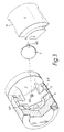
- the resilient ball arrangement of the second means can be in the form of a set of balls in a ring around the internal periphery of the casing and around the outer periphery of part of the working portion of the tool, thereby separating and isolating the two portions.
- the set of balls can be linked together.
- the balls can be located within shells which are curved to urge the balls towards their mean positions.
- a D-handled, air-operated percussive tool which incorporates apparatus for reducing vibration transmission from a working end portion 1 to a hand grip 2, thereby to reduce vibration transmission to the hand/arm of the user.
- apparatus for reducing vibration transmission from a working end portion 1 to a hand grip 2, thereby to reduce vibration transmission to the hand/arm of the user.
- Such apparatus will be briefly referred to hereafter as the "vibration isolator”.
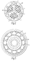
- the vibration isolator in the form illustrated comprises a male, substantially frustoconical portion 3 whose tip is located facing a female bed 4.
- the base of the frustoconical part is attached to the handle grip 2, whilst the bed 4 is attached to the working end portion 1 of the tool.
- Three substantially spherical rubber balls 5 are trapped between the portion 3 and bed 4, which is preferably of scalloped form, the number of scallops corresponding to the number of balls and each scallop serving to receive and locate its ball.
- the apparatus as depicted in Figure 1 is carrying a mean static load.
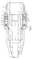
- the balls can be located in their mean positions under compression by means of nylon tubes 6A and 6B located in bores 7 of the balls 5, the tubes having portions protruding from the surfaces of the balls so that these protruding portions are located in corresponding bores 8A and 8B in the portion 3 and bed 4, respectively.
- the tubes 6A and 6B in each bore 7 are spaced apart to give sufficient clearance for compression and expansion movement of the ball 5 in which the bore is located.
- the tubes 6A, 6B may be nylon inserts which are glued, bonded or simply press fits.
- the bores can form an integral part of the compressed air supply to the working end portion of the tool from an air supply conduit 9 in the handle grip 2, into a conduit 9A passing down the centre of the tapered portion 3 and communicating with the bores 8A, 7 and 8B.
- the bores 8B lead on to a cycle valve illustrated generally at 10.
- the portion 3 need not be pure frustoconical but can be given a gently curving taper and/or can incorporate an angular change in the direction of taper.
- the tubes 6A and 6B serve to locate the balls 5 on the taper, especially when the parts 1 and 2 are driven off-centre.
- the tubes 6A, 6B simply serve as locating means.
- the modification shown in Figure 3 takes the form of three radially-extending wings 11 on the portion 3 which run in slots 4A parallel to the longitudinal axis of the tool. These wings also act as anti-rotation means if the rotational stiffness of the balls is overcome, thereby acting as a travel limiter. Also, they act as a rebound stop or travel limiter in the axial direction.
- the percussive tool will oscillate at around ⁇ 4mm at 25 Hz/sec.
- the acceleration levels experienced with the balls is very high and so the resilient material of the balls must be of a suitable hardness.
- the apparatus provides a high radial stiffness and a low (soft) axial stiffness with rising rate. In comparison, a normal coil spring would have a constant rate.
- the balls effectively provide a rising spring rate or stiffness. The rising rate can be varied by varying the degree of slope on the rolling surfaces.
- the axial stiffness is intended to be lower, and with a constant rate, but the radial stiffness is intended to be higher than is the case with the vibrator isolator at the hand grip end of the tool.
- the shells 15 and 16 are curved to urge the bracelet of balls towards their mean positions. The balls are compressed and in this case, they have a shallow curve.
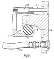
- Figure 6 shows a possible modification of the construction shown in Figures 1 to 3, in which the air line is not via the balls 5 but via a separate, flexible hose 18 connected between the hand grip 2 and the reciprocating portion 1. There are still three balls 5, each located in its own scalloped portion on the bed 4.
- the male portion 3 can be provided with planar or substantially planar faces.
- the reciprocating portion 1 is guided by three toughened pins 19 extending from the hand grip 2 parallel to the axis of the tool, each pin running as a loose fit in its own hardened bush 20. This construction provides guiding and anti-rotation means for the portion 1.
- Figure 7 shows a possible modification of the construction shown in Figures 4 and 5, in which the bracelet of balls at the actual tool 14 end is replaced by a plain sliding bearing.
- This comprises a bed 21 of polymer fitted around the portion 1 and a part-spherical, radiussed bearing tip 22 which can be of hardened steel flash chromium plated.
- a slight clearance is provided to allow for "blow past", which provides self-cleaning and allows for expansion.
Landscapes
- Engineering & Computer Science (AREA)
- Mechanical Engineering (AREA)
- Percussive Tools And Related Accessories (AREA)
- Drilling And Boring (AREA)
- Auxiliary Devices For Music (AREA)
Priority Applications (4)
| Application Number | Priority Date | Filing Date | Title |
|---|---|---|---|
| AU33227/93A AU651269B2 (en) | 1991-12-17 | 1992-12-15 | Apparatus for reducing vibration transmission in hand-held tool |
| JP5511156A JPH06507847A (ja) | 1991-12-17 | 1992-12-15 | 手持ち工具における振動伝達を低減する装置 |
| US08/104,106 US5400860A (en) | 1991-12-17 | 1992-12-15 | Apparatus for reducing vibration transmission in hand-held tool |
| KR1019930702455A KR100274746B1 (ko) | 1991-12-17 | 1992-12-15 | 손파지형 공구에서의 진동 전달 감소 장치 |
Applications Claiming Priority (2)
| Application Number | Priority Date | Filing Date | Title |
|---|---|---|---|
| GB9126979A GB2262467A (en) | 1991-12-17 | 1991-12-17 | Apparatus for reducing vibration transmission in hand-held tool |
| GB9126979 | 1991-12-17 |
Publications (2)
| Publication Number | Publication Date |
|---|---|
| EP0551719A1 EP0551719A1 (en) | 1993-07-21 |
| EP0551719B1 true EP0551719B1 (en) | 1996-11-27 |
Family
ID=10706538
Family Applications (1)
| Application Number | Title | Priority Date | Filing Date |
|---|---|---|---|
| EP19920309846 Expired - Lifetime EP0551719B1 (en) | 1991-12-17 | 1992-10-28 | Hand-held percussive tool incorporating apparatus for reducing vibration transmission to the user |
Country Status (5)
| Country | Link |
|---|---|
| EP (1) | EP0551719B1 (OSRAM) |
| DE (1) | DE69215494T2 (OSRAM) |
| ES (1) | ES2094884T3 (OSRAM) |
| GB (1) | GB2262467A (OSRAM) |
| TW (1) | TW224436B (OSRAM) |
Cited By (1)
| Publication number | Priority date | Publication date | Assignee | Title |
|---|---|---|---|---|
| CN1961135B (zh) * | 2004-04-30 | 2010-06-23 | 安斯波成就公司 | 外科手术气动马达 |
Families Citing this family (5)
| Publication number | Priority date | Publication date | Assignee | Title |
|---|---|---|---|---|
| GB2285763B (en) * | 1994-01-11 | 1997-06-11 | Ingersoll Rand Co | Fluid metering device for compressed fluid operated tool |
| KR100260309B1 (ko) * | 1997-06-11 | 2000-07-01 | 최해성 | 유압헤머 |
| GB2431610A (en) * | 2006-03-03 | 2007-05-02 | Black & Decker Inc | Handle Damping System |
| DE102009002589A1 (de) * | 2009-04-23 | 2010-10-28 | Hilti Aktiengesellschaft | Handwerkzeugmaschine |
| EP3335838A1 (de) * | 2016-12-15 | 2018-06-20 | HILTI Aktiengesellschaft | Handwerkzeugmaschine |
Family Cites Families (11)
| Publication number | Priority date | Publication date | Assignee | Title |
|---|---|---|---|---|
| GB453213A (en) * | 1934-11-29 | 1935-06-08 | Jacques D Albay | Improvements in resilient connections and joints |
| NL41026C (OSRAM) * | 1936-02-21 | |||
| US2440150A (en) * | 1945-01-31 | 1948-04-20 | Independent Pneumatic Tool Co | Compression member |
| US2468901A (en) * | 1945-10-20 | 1949-05-03 | Gen Tire & Rubber Co | Cushioning and virration damping support |
| GB721636A (en) * | 1951-09-21 | 1955-01-12 | Giulio Virgilio Scanzi | Improvements relating to shock-absorbers for vehicles |
| BE527846A (OSRAM) * | 1953-06-19 | |||
| CS149009B1 (OSRAM) * | 1971-02-01 | 1973-05-24 | ||
| SE8107226L (sv) * | 1981-01-28 | 1982-07-29 | Byggergonomilaboratoriet Hb | Vibrationsdempande anordning |
| GB8516839D0 (en) * | 1985-07-03 | 1985-08-07 | Isolated Systems Ltd | Anti-vibration mount |
| CH669142A5 (de) * | 1986-04-04 | 1989-02-28 | Sig Schweiz Industrieges | Presslufthammer. |
| PL153240B1 (en) * | 1988-03-29 | 1991-03-29 | Politechnika Poznanska | Vibration damping arrangement for hand tools |
-
1991
- 1991-12-17 GB GB9126979A patent/GB2262467A/en not_active Withdrawn
-
1992
- 1992-07-21 TW TW81105771A patent/TW224436B/zh active
- 1992-10-28 DE DE1992615494 patent/DE69215494T2/de not_active Expired - Fee Related
- 1992-10-28 EP EP19920309846 patent/EP0551719B1/en not_active Expired - Lifetime
- 1992-10-28 ES ES92309846T patent/ES2094884T3/es not_active Expired - Lifetime
Cited By (1)
| Publication number | Priority date | Publication date | Assignee | Title |
|---|---|---|---|---|
| CN1961135B (zh) * | 2004-04-30 | 2010-06-23 | 安斯波成就公司 | 外科手术气动马达 |
Also Published As
| Publication number | Publication date |
|---|---|
| GB2262467A (en) | 1993-06-23 |
| EP0551719A1 (en) | 1993-07-21 |
| GB9126979D0 (en) | 1992-02-19 |
| TW224436B (OSRAM) | 1994-06-01 |
| ES2094884T3 (es) | 1997-02-01 |
| DE69215494T2 (de) | 1997-05-22 |
| DE69215494D1 (de) | 1997-01-09 |
Similar Documents
| Publication | Publication Date | Title |
|---|---|---|
| AU651269B2 (en) | Apparatus for reducing vibration transmission in hand-held tool | |
| US5213167A (en) | Apparatus for reducing vibration transmission in hand-held tool | |
| CA1221991A (en) | Vibration damper | |
| EP1358968A1 (en) | Power tool with a vibration absorbing handle | |
| CN102554877A (zh) | 手持工具机 | |
| EP0551719B1 (en) | Hand-held percussive tool incorporating apparatus for reducing vibration transmission to the user | |
| US3735824A (en) | Arrangements in and relating to a chiselling hammer or similar percussion machine | |
| CA1108886A (en) | Linear motion impactor device | |
| CA2605325C (en) | Anti-vibratory handle for percussive and other reciprocating tools | |
| US4921053A (en) | Vibro-isolation of connections of structural units of hand tools | |
| JPH08506866A (ja) | ダウンザホール衝撃装置用可逆ケーシング | |
| WO1993011911A1 (en) | Apparatus for reducing vibration transmission in hand-held tool | |
| WO1981003518A1 (en) | Vibration isolator device for a percussion tool | |
| ATE424974T1 (de) | Schlagvorrichtung | |
| EP0423121B1 (en) | An apparatus with two end positions generating a reciprocating motion | |
| US5349809A (en) | Shaft for an open-end spinning rotor assembly | |
| US2820433A (en) | Hammer pistons for percussion machine and tools | |
| CN212235270U (zh) | 一种筋膜枪传动装置 | |
| US2812745A (en) | Hammer pistons and tools provided therewith | |
| CN208601463U (zh) | 一种凿岩机用减振扶手把 | |
| EP0224859B1 (en) | Air driven impact operated ground piercing tool | |
| US12458565B2 (en) | Stick-slip frictional swivel coupling for a massage tool reciprocated at forced frequency | |
| CN110529552A (zh) | 减振支脚以及减振脚垫 | |
| CN111870504B (zh) | 一种筋膜枪传动装置 | |
| EP0035984A1 (en) | A recoil damper |
Legal Events
| Date | Code | Title | Description |
|---|---|---|---|
| PUAI | Public reference made under article 153(3) epc to a published international application that has entered the european phase |
Free format text: ORIGINAL CODE: 0009012 |
|
| AK | Designated contracting states |
Kind code of ref document: A1 Designated state(s): DE ES FR GB IT PT SE |
|
| 17P | Request for examination filed |
Effective date: 19940117 |
|
| 17Q | First examination report despatched |
Effective date: 19950327 |
|
| GRAG | Despatch of communication of intention to grant |
Free format text: ORIGINAL CODE: EPIDOS AGRA |
|
| GRAH | Despatch of communication of intention to grant a patent |
Free format text: ORIGINAL CODE: EPIDOS IGRA |
|
| GRAH | Despatch of communication of intention to grant a patent |
Free format text: ORIGINAL CODE: EPIDOS IGRA |
|
| GRAA | (expected) grant |
Free format text: ORIGINAL CODE: 0009210 |
|
| AK | Designated contracting states |
Kind code of ref document: B1 Designated state(s): DE ES FR GB IT PT SE |
|
| ITF | It: translation for a ep patent filed | ||
| REF | Corresponds to: |
Ref document number: 69215494 Country of ref document: DE Date of ref document: 19970109 |
|
| REG | Reference to a national code |
Ref country code: ES Ref legal event code: FG2A Ref document number: 2094884 Country of ref document: ES Kind code of ref document: T3 |
|
| PG25 | Lapsed in a contracting state [announced via postgrant information from national office to epo] |
Ref country code: PT Effective date: 19970227 |
|
| ET | Fr: translation filed | ||
| PLBE | No opposition filed within time limit |
Free format text: ORIGINAL CODE: 0009261 |
|
| 26N | No opposition filed | ||
| REG | Reference to a national code |
Ref country code: GB Ref legal event code: IF02 |
|
| PGFP | Annual fee paid to national office [announced via postgrant information from national office to epo] |
Ref country code: ES Payment date: 20021106 Year of fee payment: 11 |
|
| PG25 | Lapsed in a contracting state [announced via postgrant information from national office to epo] |
Ref country code: ES Free format text: LAPSE BECAUSE OF NON-PAYMENT OF DUE FEES Effective date: 20031029 |
|
| PGFP | Annual fee paid to national office [announced via postgrant information from national office to epo] |
Ref country code: GB Payment date: 20041020 Year of fee payment: 13 Ref country code: FR Payment date: 20041020 Year of fee payment: 13 |
|
| PGFP | Annual fee paid to national office [announced via postgrant information from national office to epo] |
Ref country code: SE Payment date: 20041021 Year of fee payment: 13 |
|
| PGFP | Annual fee paid to national office [announced via postgrant information from national office to epo] |
Ref country code: DE Payment date: 20041130 Year of fee payment: 13 |
|
| REG | Reference to a national code |
Ref country code: ES Ref legal event code: FD2A Effective date: 20031029 |
|
| PG25 | Lapsed in a contracting state [announced via postgrant information from national office to epo] |
Ref country code: IT Free format text: LAPSE BECAUSE OF NON-PAYMENT OF DUE FEES;WARNING: LAPSES OF ITALIAN PATENTS WITH EFFECTIVE DATE BEFORE 2007 MAY HAVE OCCURRED AT ANY TIME BEFORE 2007. THE CORRECT EFFECTIVE DATE MAY BE DIFFERENT FROM THE ONE RECORDED. Effective date: 20051028 Ref country code: GB Free format text: LAPSE BECAUSE OF NON-PAYMENT OF DUE FEES Effective date: 20051028 |
|
| PG25 | Lapsed in a contracting state [announced via postgrant information from national office to epo] |
Ref country code: SE Free format text: LAPSE BECAUSE OF NON-PAYMENT OF DUE FEES Effective date: 20051029 |
|
| PG25 | Lapsed in a contracting state [announced via postgrant information from national office to epo] |
Ref country code: DE Free format text: LAPSE BECAUSE OF NON-PAYMENT OF DUE FEES Effective date: 20060503 |
|
| EUG | Se: european patent has lapsed | ||
| GBPC | Gb: european patent ceased through non-payment of renewal fee |
Effective date: 20051028 |
|
| PG25 | Lapsed in a contracting state [announced via postgrant information from national office to epo] |
Ref country code: FR Free format text: LAPSE BECAUSE OF NON-PAYMENT OF DUE FEES Effective date: 20060630 |
|
| REG | Reference to a national code |
Ref country code: FR Ref legal event code: ST Effective date: 20060630 |